EP0307687A1 - Connection de deux éléments, en paticulier d'un essuie-glace sur la carrosserie d'une voiture - Google Patents
Connection de deux éléments, en paticulier d'un essuie-glace sur la carrosserie d'une voiture Download PDFInfo
- Publication number
- EP0307687A1 EP0307687A1 EP88113938A EP88113938A EP0307687A1 EP 0307687 A1 EP0307687 A1 EP 0307687A1 EP 88113938 A EP88113938 A EP 88113938A EP 88113938 A EP88113938 A EP 88113938A EP 0307687 A1 EP0307687 A1 EP 0307687A1
- Authority
- EP
- European Patent Office
- Prior art keywords
- plug
- receiving part
- connection according
- connection
- elements
- Prior art date
- Legal status (The legal status is an assumption and is not a legal conclusion. Google has not performed a legal analysis and makes no representation as to the accuracy of the status listed.)
- Withdrawn
Links
- 239000000463 material Substances 0.000 claims abstract description 38
- 239000000945 filler Substances 0.000 claims description 8
- 238000000034 method Methods 0.000 claims description 8
- 238000007789 sealing Methods 0.000 claims description 5
- 239000004033 plastic Substances 0.000 claims description 4
- 238000013016 damping Methods 0.000 claims description 3
- 230000006835 compression Effects 0.000 claims description 2
- 238000007906 compression Methods 0.000 claims description 2
- 239000011347 resin Substances 0.000 claims description 2
- 229920005989 resin Polymers 0.000 claims description 2
- 229920002725 thermoplastic elastomer Polymers 0.000 claims description 2
- 239000002184 metal Substances 0.000 claims 2
- 150000001875 compounds Chemical class 0.000 claims 1
- 239000011796 hollow space material Substances 0.000 abstract 2
- 238000013461 design Methods 0.000 description 3
- 239000007788 liquid Substances 0.000 description 2
- 239000011344 liquid material Substances 0.000 description 2
- 238000005260 corrosion Methods 0.000 description 1
- 230000007797 corrosion Effects 0.000 description 1
- 238000011161 development Methods 0.000 description 1
- 238000003780 insertion Methods 0.000 description 1
- 230000037431 insertion Effects 0.000 description 1
- 238000004519 manufacturing process Methods 0.000 description 1
- 238000012545 processing Methods 0.000 description 1
- 239000011345 viscous material Substances 0.000 description 1
Images
Classifications
-
- B—PERFORMING OPERATIONS; TRANSPORTING
- B60—VEHICLES IN GENERAL
- B60Q—ARRANGEMENT OF SIGNALLING OR LIGHTING DEVICES, THE MOUNTING OR SUPPORTING THEREOF OR CIRCUITS THEREFOR, FOR VEHICLES IN GENERAL
- B60Q1/00—Arrangement of optical signalling or lighting devices, the mounting or supporting thereof or circuits therefor
- B60Q1/02—Arrangement of optical signalling or lighting devices, the mounting or supporting thereof or circuits therefor the devices being primarily intended to illuminate the way ahead or to illuminate other areas of way or environments
- B60Q1/04—Arrangement of optical signalling or lighting devices, the mounting or supporting thereof or circuits therefor the devices being primarily intended to illuminate the way ahead or to illuminate other areas of way or environments the devices being headlights
- B60Q1/0408—Arrangement of optical signalling or lighting devices, the mounting or supporting thereof or circuits therefor the devices being primarily intended to illuminate the way ahead or to illuminate other areas of way or environments the devices being headlights built into the vehicle body, e.g. details concerning the mounting of the headlamps on the vehicle body
- B60Q1/0441—Arrangement of optical signalling or lighting devices, the mounting or supporting thereof or circuits therefor the devices being primarily intended to illuminate the way ahead or to illuminate other areas of way or environments the devices being headlights built into the vehicle body, e.g. details concerning the mounting of the headlamps on the vehicle body the housing being fastened onto the vehicle body using means other than screws
-
- B—PERFORMING OPERATIONS; TRANSPORTING
- B29—WORKING OF PLASTICS; WORKING OF SUBSTANCES IN A PLASTIC STATE IN GENERAL
- B29C—SHAPING OR JOINING OF PLASTICS; SHAPING OF MATERIAL IN A PLASTIC STATE, NOT OTHERWISE PROVIDED FOR; AFTER-TREATMENT OF THE SHAPED PRODUCTS, e.g. REPAIRING
- B29C65/00—Joining or sealing of preformed parts, e.g. welding of plastics materials; Apparatus therefor
- B29C65/02—Joining or sealing of preformed parts, e.g. welding of plastics materials; Apparatus therefor by heating, with or without pressure
- B29C65/40—Applying molten plastics, e.g. hot melt
- B29C65/42—Applying molten plastics, e.g. hot melt between pre-assembled parts
-
- B—PERFORMING OPERATIONS; TRANSPORTING
- B29—WORKING OF PLASTICS; WORKING OF SUBSTANCES IN A PLASTIC STATE IN GENERAL
- B29C—SHAPING OR JOINING OF PLASTICS; SHAPING OF MATERIAL IN A PLASTIC STATE, NOT OTHERWISE PROVIDED FOR; AFTER-TREATMENT OF THE SHAPED PRODUCTS, e.g. REPAIRING
- B29C66/00—General aspects of processes or apparatus for joining preformed parts
- B29C66/50—General aspects of joining tubular articles; General aspects of joining long products, i.e. bars or profiled elements; General aspects of joining single elements to tubular articles, hollow articles or bars; General aspects of joining several hollow-preforms to form hollow or tubular articles
- B29C66/51—Joining tubular articles, profiled elements or bars; Joining single elements to tubular articles, hollow articles or bars; Joining several hollow-preforms to form hollow or tubular articles
- B29C66/54—Joining several hollow-preforms, e.g. half-shells, to form hollow articles, e.g. for making balls, containers; Joining several hollow-preforms, e.g. half-cylinders, to form tubular articles
-
- F—MECHANICAL ENGINEERING; LIGHTING; HEATING; WEAPONS; BLASTING
- F16—ENGINEERING ELEMENTS AND UNITS; GENERAL MEASURES FOR PRODUCING AND MAINTAINING EFFECTIVE FUNCTIONING OF MACHINES OR INSTALLATIONS; THERMAL INSULATION IN GENERAL
- F16B—DEVICES FOR FASTENING OR SECURING CONSTRUCTIONAL ELEMENTS OR MACHINE PARTS TOGETHER, e.g. NAILS, BOLTS, CIRCLIPS, CLAMPS, CLIPS OR WEDGES; JOINTS OR JOINTING
- F16B3/00—Key-type connections; Keys
- F16B3/005—Key-type connections; Keys the key being formed by solidification of injected material
-
- B—PERFORMING OPERATIONS; TRANSPORTING
- B29—WORKING OF PLASTICS; WORKING OF SUBSTANCES IN A PLASTIC STATE IN GENERAL
- B29C—SHAPING OR JOINING OF PLASTICS; SHAPING OF MATERIAL IN A PLASTIC STATE, NOT OTHERWISE PROVIDED FOR; AFTER-TREATMENT OF THE SHAPED PRODUCTS, e.g. REPAIRING
- B29C66/00—General aspects of processes or apparatus for joining preformed parts
- B29C66/70—General aspects of processes or apparatus for joining preformed parts characterised by the composition, physical properties or the structure of the material of the parts to be joined; Joining with non-plastics material
- B29C66/71—General aspects of processes or apparatus for joining preformed parts characterised by the composition, physical properties or the structure of the material of the parts to be joined; Joining with non-plastics material characterised by the composition of the plastics material of the parts to be joined
Definitions
- the invention relates to a connection between two elements, in particular a frame of a wiper system with a motor vehicle body, according to the features of the preamble of claim 1.
- the frame of a wiper system has so far mostly been attached to the body of a motor vehicle by means of a screw connection.
- This requires additional components, namely a screw or a nut, the assembly of which is very cumbersome and time-consuming.
- Other add-on parts of a motor vehicle, for example the lights, are often held on the body alone via a snap-in connection. Additional components are not required, but such a snap connection withstands only comparatively small forces.
- the previously known connection techniques with such locking elements are not suitable for fastening a wiper system to a motor vehicle body for reasons of stability.
- the present invention is therefore based on the object of creating a connection between two elements which can withstand greater forces, but is still possible as far as possible without additional components which are difficult to handle and thus can be produced fully automatically.
- the invention is essentially based on the idea that the two elements can be connected to one another in a dimensionally stable manner if a curable material is filled into a cavity formed between the parts.
- a curable material can be supplied much better by means of an automatic machine than, for example, a screw or nut.
- the inventive idea could be implemented in such a way that a cylindrical receiving part with a smooth inner wall is placed coaxially over a cylindrical plug-in part with a smooth outer wall and the cavity between the adjacent walls of the plug-in part and the receiving part is filled with the material. Sufficient stability is usually not given with such a connection, which is why an embodiment with the features of claim 2 is preferred.
- a form fit is created between the hardened material and the plug-in part and a form fit between the hardened material and the receiving part, so that the two parts are positively locked to one another via this hardened material.
- a cavity is to be delimited by the plug-in part and the receiving part, which cavity is completely closed except for small filling holes.
- ma can use liquid materials with a relatively long curing time and is not limited to the use of viscous materials.
- the plug-in part and / or the receiving part can be formed in one piece with the associated element.
- the plug-in part can be designed as a cylindrical extension which is stamped directly out of the body wall.
- this plug-in part and / or the receiving part can also be designed as a separate component and, for example, suspended from the associated element via an attenuator.
- the invention also relates to a method for connecting two elements, the essential idea of which is that first the the two elements are nested in the correct position and then fill the cavity formed with a hardenable material.
- a hardenable material which has already changed to the plastic state, is applied to the plug-in part and / or the receiving part and only then are the two elements joined in the correct position, this material then filling the cavity between the plug-in part and the receiving part.
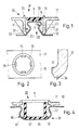
- 10 denotes the body of a motor vehicle to which a frame 11 of a windshield wiper system is to be fixed in a dimensionally stable manner.
- a plug-in part generally designated 20
- This plug-in part 20 thus has a mushroom-shaped cross-section with a surface section 22, the normal N of which has a component K in the plug-in or assembly direction or in the axial direction A of the plug-in part 20.
- an undercut is formed, which ensures a dimensionally stable locking between the two elements 10 and 11 to be connected, which will be explained later.
- a receiving part, generally designated 30, is integrally formed on the other element, namely the frame 11, a receiving part, generally designated 30, is integrally formed.
- a cylindrical wall 31 protrudes from the frame 11, at the free end of which an inwardly directed annular flange-like projection 32 is provided.
- cutouts 34 which serve as filler holes for a hardenable material designated 40.
- These filler holes 34 lie within a filler neck 35 which is cylindrical, but possibly also elliptical or has a different design, and which projects from the side of the frame opposite the cylindrical wall 31. This filler neck serves to attach the filler neck emitting material 40, which is not shown in the drawing, however.
- Fig. 1 shows the two elements in the final, locked position. 1 shows in particular that a cavity 41 is formed between the receiving part 30 and the plug-in part 20, which is completely closed except for the small filling holes 34.
- the flange-like extension 32 on the receiving part 30 lies flat on an edge region 23 around the plug-in part 20.
- a sealing lip 36 can be provided which is elastically deformable and compensates for the tolerances in the insertion direction A.
- This sealing lip 36 can be integrally formed directly on the plug-in part or - as shown in FIG. 3 - on the receiving part 30, in particular if this receiving part is made of plastic.
- the frame 11 is first inserted with its receiving part 30 over the plug-in part 20 on the body 10, whereby means can be provided which reduce the two elements in this preassembled position Hold the locking force together.
- These locking means can be designed independently of the connection shown in FIG. 1, but designs are also conceivable in which these locking means are integrated in the connection area.
- the low elasticity of the circumferential side wall 31 of the receiving part 30 in connection with the flange-like extension 32 could be regarded as a latching element which holds the frame on the plug-in part 20 until the motor vehicle to be assembled arrives at the processing station at which the hardenable material is filled . 1 it can be assumed that the two elements 10 and 11 are first inserted into one another in such a way that a cavity 41 is formed and that the curable material is then filled into liquid form in this almost completely closed cavity. This is possible without any manual intervention.
- the material 40 forms a kind of bar between the two elements 10 and 11. This material rests on undercuts on both elements in such a way that the two elements cannot be detached from one another without finally destroying the connection. If you try to pull the frame 11 against the direction of the arrow P from the body 10, for example, the flange-like extension 32, which forms the undercut on the receiving part, is pressed against the bolt, i.e. the curable material, and tries to pull it off the plug-in part. However, this is not possible because, with another section, this bolt rests on the inclined surface section 22 on the plug-in part 20.
- the main idea of the present invention can thus also be formulated in such a way that a bolt connecting the two elements is created indirectly in a tool shape which is created by the two parts to be connected themselves. This eliminates the need for any manual feeding of an additional connecting element.
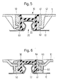
- Fig. 4 essentially represents a reversal of the embodiment shown in Fig. 1, because now the receiving part 30 is formed on the body 10, while the plug-in part 20 is integrally formed on the frame 11.
- the receptacle 37 is embossed directly out of the body panel, the side wall 38 then through Compression in the axial direction A is bulged out laterally. 4, the cavity 41 is almost completely closed.
- the wiper system is fixed to a partial area of the body that deviates only slightly from the horizontal. With such an arrangement, liquid, curable material can therefore be filled into this pot-shaped receiving part 30 without difficulty before the plug-in part is inserted on the frame 11 in a next working step.
- This process with a reverse order of the work steps will preferably be used when using a material that has already changed to the plastic state.
- both the receiving part and the plug-in part were formed in one piece with the associated element.
- 5 to 8 now show exemplary embodiments in which the receiving part 30 is designed as a separate component and is connected to the frame 11 via an attenuator 50. It can be seen from the drawing that the actual receiving part 30 in the embodiment according to FIG. 5 does not differ significantly from the receiving part shown in FIG. 1. However, it has an outwardly projecting ring flange 61 which engages in a corresponding groove on the attenuator. On the frame 11 there is now a cylindrical wall section 62 with an inwardly directed ring flange 63, which likewise engages in a corresponding recess on the damping member 50.
- this attenuator 50 is, so to speak, tied into the frame 11, while on the other hand, the actual holding element is linked into this attenuator 50, so that there is a pre-assembled unit is fixed to the plug-in part 20 of the body according to the previously described method.
- the frame 11, the holding element 30 and the damping member 50 are each to be manufactured as separate components independently of one another, a simplified manufacturing method will be explained with reference to FIG. 6.
- the receiving part 30 and the frame 11 are initially to be made in one piece, with a connection to be made at the edges 64 and 65 of the ring flanges 61 and 63, respectively.
- the assembly thus produced is then inserted into a tool, and when the thermoplastic rubber is injected for the attenuator 50, the holding element is separated from the frame 11.
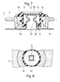
- the plug-in part 20 differs from the previously described exemplary embodiments essentially by a different shape of the plug-in part 20, which is embossed as a cylindrical pin from the holding plate or the body and is then radially pressed in at four points on the lateral surface, so that in this height of the pegs has approximately a quadrangular cross section Q.
- the cavity 41 for the hardenable material is closed off at the top by a plate 70 with a small filling opening.
- This plate 70 is locked in a circumferential groove 71 on the receiving part 30.
- the plate 71 rests on the head of the plug-in part 20, as a result of which the position of the frame 11 in relation to the body is predetermined.
- This plate could also be used subsequently, i.e. after the hardenable material has been filled in, and - without a filling opening - completely seal off the cavity for the material. This process has particular advantages when using liquid materials.
- a two-component resin is preferably used as the hardenable material, which does not necessarily have to form a connection with one of the two elements to be connected, since in its hardened form - as already explained - it forms a bar between the parts to be connected.
- the hardenable material does not necessarily have to form a connection with one of the two elements to be connected, since in its hardened form - as already explained - it forms a bar between the parts to be connected.
- connection according to the invention is that a fully automatic assembly is possible, but the connection still withstands all requirements with regard to strength and operating time. Corrosion problems as with the known screw connections occur here not on. In addition, it is not necessary to incorporate openings in the body, so that sealing problems are also eliminated. 5 to 8, noises are not transmitted because of the attenuator, and this type of connection is therefore vibration-free to the desired extent.
- plug-in part 20 is designed as a separate screw bolt which is rotatably held in an element 10, 11 with a first threaded section and is immersed in the hardenable material 40 with a second threaded section.
- disassembly is also possible in a simple manner because the screw bolt creates a nut thread section in the hardening material and can later be unscrewed from the hardened material. It is therefore easy to fix a frame according to the present invention to older bodies equipped with such screws, the threaded bolt being fixed rigidly or rotatably to the body.
- the basic idea of the invention is in no way limited to windshield wiper systems; rather, all other add-on parts, such as lights and headlights, window lifting systems, trim strips, exhaust systems, can be fixed in a dimensionally stable manner according to the principle of the present invention.
Landscapes
- Engineering & Computer Science (AREA)
- Mechanical Engineering (AREA)
- General Engineering & Computer Science (AREA)
- Body Structure For Vehicles (AREA)
Applications Claiming Priority (2)
| Application Number | Priority Date | Filing Date | Title |
|---|---|---|---|
| DE3729104 | 1987-09-01 | ||
| DE19873729104 DE3729104A1 (de) | 1987-09-01 | 1987-09-01 | Verbindung zweier elemente, insbesondere eines rahmens einer wischanlage mit einer kraftfahrzeugkarosserie sowie verfahren zur verbindung dieser beiden elemente |
Publications (1)
| Publication Number | Publication Date |
|---|---|
| EP0307687A1 true EP0307687A1 (fr) | 1989-03-22 |
Family
ID=6334926
Family Applications (1)
| Application Number | Title | Priority Date | Filing Date |
|---|---|---|---|
| EP88113938A Withdrawn EP0307687A1 (fr) | 1987-09-01 | 1988-08-26 | Connection de deux éléments, en paticulier d'un essuie-glace sur la carrosserie d'une voiture |
Country Status (2)
| Country | Link |
|---|---|
| EP (1) | EP0307687A1 (fr) |
| DE (1) | DE3729104A1 (fr) |
Cited By (3)
| Publication number | Priority date | Publication date | Assignee | Title |
|---|---|---|---|---|
| EP0450330A1 (fr) * | 1990-03-31 | 1991-10-09 | B. Braun Melsungen AG | Raccord à tuyau |
| GB2341819A (en) * | 1998-08-03 | 2000-03-29 | Ford Motor Co | Sealed joint for an injection moulded lamp assembly |
| US8087963B2 (en) | 2005-10-28 | 2012-01-03 | Dow Corning Corporation | Joints for multi-component molded articles |
Families Citing this family (7)
| Publication number | Priority date | Publication date | Assignee | Title |
|---|---|---|---|---|
| DE4311442C1 (de) † | 1993-04-07 | 1994-07-07 | Ver Glaswerke Gmbh | Verfahren zur Schraubbefestigung eines Befestigungs- oder Halteelements an einer Verbundglasscheibe und Anwendung des Verfahrens |
| DE4319311A1 (de) * | 1993-06-11 | 1994-12-15 | Cerasiv Gmbh | Anordnung zur Befestigung von keramischen Formkörpern auf einem Trägerkörper |
| DE19512102A1 (de) * | 1995-04-03 | 1996-10-10 | Kurt Prof Dr Ing Koppe | Verfahren zur Verbindung von umformbaren Blechbauteilen, vorzugsweise Feinblechen, durch Kleben |
| JP3409561B2 (ja) * | 1996-02-19 | 2003-05-26 | 東海ゴム工業株式会社 | 車両用構造体の製造方法 |
| DE19929480A1 (de) * | 1999-06-26 | 2000-12-28 | Gerhard Koetting | Klebverfahren |
| DE10328378B4 (de) * | 2003-06-24 | 2005-05-19 | Siemens Ag | Verfahren zur Herstellung einer formschlüssigen Verbindung |
| DE102016210664A1 (de) | 2016-06-15 | 2017-12-21 | Bayerische Motorenwerke Aktiengesellschaft | Verfahren zum Verbinden zweier Bauteile sowie Bauteilanordnung |
Citations (6)
| Publication number | Priority date | Publication date | Assignee | Title |
|---|---|---|---|---|
| FR1114770A (fr) * | 1953-12-07 | 1956-04-17 | Dispositif d'assemblage pour la réparation de pièces métalliques cassées | |
| FR1391945A (fr) * | 1964-01-29 | 1965-03-12 | Haut Rhin Manufacture Machines | Procédé d'assemblage permanent de deux éléments manchonnés l'un sur l'autre |
| CH490618A (de) * | 1968-12-20 | 1970-05-15 | Robert Schenk Fahrzeugfabrik F | Einrichtung zum Zusammenfügen aneinanderstossender Elemente |
| DE2206588A1 (de) * | 1971-08-27 | 1973-08-02 | Modern Plastic Co | Spritzgussverfahren und vorrichtung |
| US3916502A (en) * | 1971-09-17 | 1975-11-04 | Luigi Bagnulo | Method of establishing a pipe joint |
| US3992846A (en) * | 1974-03-21 | 1976-11-23 | Rohr Industries, Inc. | Compound filled key interlock joint |
-
1987
- 1987-09-01 DE DE19873729104 patent/DE3729104A1/de not_active Withdrawn
-
1988
- 1988-08-26 EP EP88113938A patent/EP0307687A1/fr not_active Withdrawn
Patent Citations (6)
| Publication number | Priority date | Publication date | Assignee | Title |
|---|---|---|---|---|
| FR1114770A (fr) * | 1953-12-07 | 1956-04-17 | Dispositif d'assemblage pour la réparation de pièces métalliques cassées | |
| FR1391945A (fr) * | 1964-01-29 | 1965-03-12 | Haut Rhin Manufacture Machines | Procédé d'assemblage permanent de deux éléments manchonnés l'un sur l'autre |
| CH490618A (de) * | 1968-12-20 | 1970-05-15 | Robert Schenk Fahrzeugfabrik F | Einrichtung zum Zusammenfügen aneinanderstossender Elemente |
| DE2206588A1 (de) * | 1971-08-27 | 1973-08-02 | Modern Plastic Co | Spritzgussverfahren und vorrichtung |
| US3916502A (en) * | 1971-09-17 | 1975-11-04 | Luigi Bagnulo | Method of establishing a pipe joint |
| US3992846A (en) * | 1974-03-21 | 1976-11-23 | Rohr Industries, Inc. | Compound filled key interlock joint |
Cited By (4)
| Publication number | Priority date | Publication date | Assignee | Title |
|---|---|---|---|---|
| EP0450330A1 (fr) * | 1990-03-31 | 1991-10-09 | B. Braun Melsungen AG | Raccord à tuyau |
| GB2341819A (en) * | 1998-08-03 | 2000-03-29 | Ford Motor Co | Sealed joint for an injection moulded lamp assembly |
| GB2341819B (en) * | 1998-08-03 | 2003-04-09 | Ford Motor Co | Sealed joint for a multi-component injection moulded automotive lamp assembly |
| US8087963B2 (en) | 2005-10-28 | 2012-01-03 | Dow Corning Corporation | Joints for multi-component molded articles |
Also Published As
| Publication number | Publication date |
|---|---|
| DE3729104A1 (de) | 1989-03-09 |
Similar Documents
| Publication | Publication Date | Title |
|---|---|---|
| EP2004453B1 (fr) | Crashbox et systeme d'amortissement avec crashbox | |
| DE69601741T2 (de) | Glasscheibe, insbesondere für Kraftfahrzeuge, prepariert zum Montieren durch Klebung | |
| DE69202484T2 (de) | Verfahren und Vorrichtung zur Befestigung von Platten an Raumfachwerken. | |
| EP1899565B1 (fr) | Adaptateur et procede pour relier un moteur electrique avec une interface transmission d'une partie carrosserie | |
| DE69310453T2 (de) | Steuerungseinrichtung der Neigung eines verstellbaren Teils eines Scheinwerfers und Befestigungsvorrichtung | |
| EP2590840A1 (fr) | Dispositif de fixation servant à la fixation de composants de véhicules automobiles | |
| DE19806827A1 (de) | Verbindung zwischen einem Träger und einem Plattenelement | |
| DE3818464C1 (fr) | ||
| DE3742719A1 (de) | Verfahren zum herstellen einer deckel und dichtung umfassenden baugruppe fuer fahrzeugdaecher | |
| EP0307687A1 (fr) | Connection de deux éléments, en paticulier d'un essuie-glace sur la carrosserie d'une voiture | |
| DE102005047390B4 (de) | Trägerrahmen, insbesondere für Dachsysteme im Kraftfahrzeugbereich | |
| DE10220985A1 (de) | Verfahren zur lagegenauen Ausrichtung und Montage von zwei Bauteilen auf einem Trägerbauteil | |
| WO2018086839A1 (fr) | Vis de réglage | |
| DE102011018525A1 (de) | Verfahren und Vorrichtung zur Befestigung eines ersten Bauteils an einem zweiten Bauteil | |
| DE102013200689B4 (de) | Befestigungsvorrichtung | |
| DE3114283A1 (de) | "befestigungselement aus kunststoff, insbesondere zur loesbaren befestigung von flachen werkstuecken" | |
| WO2007062637A1 (fr) | Dispositif d'entrainement pour un element de vehicule mobile | |
| EP1545964A1 (fr) | Composant hybride a elements de fixation en plastique moules par injection pour vehicules automobiles et procede de reparation dudit composant | |
| WO2004054831A1 (fr) | Procede pour produire une portiere de vehicule automobile et portiere produite selon ledit procede | |
| DE3637162A1 (de) | Vorderwagen eines kraftfahrzeuges, insbesondere eines personenkraftwagens | |
| EP0531720A1 (fr) | Système de fixation pour des éléments de montage visibles pour véhicules, en particulier véhicules automobiles | |
| WO2012013352A1 (fr) | Pré-ébauche pour une partie d'habillage intérieur d'un véhicule et une partie d'habillage intérieur | |
| DE102013012532A1 (de) | Befestigungsanordnung | |
| DE19844813A1 (de) | Verfahren zum Einbau von Türrahmen | |
| WO2010086269A1 (fr) | Arbre de direction télescopique |
Legal Events
| Date | Code | Title | Description |
|---|---|---|---|
| PUAI | Public reference made under article 153(3) epc to a published international application that has entered the european phase |
Free format text: ORIGINAL CODE: 0009012 |
|
| AK | Designated contracting states |
Kind code of ref document: A1 Designated state(s): ES FR GB IT SE |
|
| STAA | Information on the status of an ep patent application or granted ep patent |
Free format text: STATUS: THE APPLICATION IS DEEMED TO BE WITHDRAWN |
|
| 18D | Application deemed to be withdrawn |
Effective date: 19890923 |