EP0307780A1 - Dichtung mit variablen Durchmessern für die Abdichtung zwischen einem äusseren Rohr und inneren Rohren oder Stangen - Google Patents
Dichtung mit variablen Durchmessern für die Abdichtung zwischen einem äusseren Rohr und inneren Rohren oder Stangen Download PDFInfo
- Publication number
- EP0307780A1 EP0307780A1 EP88114600A EP88114600A EP0307780A1 EP 0307780 A1 EP0307780 A1 EP 0307780A1 EP 88114600 A EP88114600 A EP 88114600A EP 88114600 A EP88114600 A EP 88114600A EP 0307780 A1 EP0307780 A1 EP 0307780A1
- Authority
- EP
- European Patent Office
- Prior art keywords
- external
- internal
- section
- cross
- tubes
- Prior art date
- Legal status (The legal status is an assumption and is not a legal conclusion. Google has not performed a legal analysis and makes no representation as to the accuracy of the status listed.)
- Granted
Links
- 238000007789 sealing Methods 0.000 title description 5
- 230000002093 peripheral effect Effects 0.000 claims abstract description 35
- 239000000463 material Substances 0.000 claims abstract description 6
- PEDCQBHIVMGVHV-UHFFFAOYSA-N Glycerine Chemical compound OCC(O)CO PEDCQBHIVMGVHV-UHFFFAOYSA-N 0.000 claims abstract description 4
- 239000013536 elastomeric material Substances 0.000 claims description 8
- 238000012856 packing Methods 0.000 abstract 1
- 229920001971 elastomer Polymers 0.000 description 7
- 229920000297 Rayon Polymers 0.000 description 6
- 239000002964 rayon Substances 0.000 description 6
- RRHGJUQNOFWUDK-UHFFFAOYSA-N Isoprene Chemical compound CC(=C)C=C RRHGJUQNOFWUDK-UHFFFAOYSA-N 0.000 description 2
- 239000002184 metal Substances 0.000 description 2
- 229920001195 polyisoprene Polymers 0.000 description 2
- 230000000712 assembly Effects 0.000 description 1
- 238000000429 assembly Methods 0.000 description 1
- 230000000903 blocking effect Effects 0.000 description 1
- 239000013013 elastic material Substances 0.000 description 1
- 238000009434 installation Methods 0.000 description 1
- 235000012830 plain croissants Nutrition 0.000 description 1
- 239000007787 solid Substances 0.000 description 1
Images


Classifications
-
- F—MECHANICAL ENGINEERING; LIGHTING; HEATING; WEAPONS; BLASTING
- F16—ENGINEERING ELEMENTS AND UNITS; GENERAL MEASURES FOR PRODUCING AND MAINTAINING EFFECTIVE FUNCTIONING OF MACHINES OR INSTALLATIONS; THERMAL INSULATION IN GENERAL
- F16L—PIPES; JOINTS OR FITTINGS FOR PIPES; SUPPORTS FOR PIPES, CABLES OR PROTECTIVE TUBING; MEANS FOR THERMAL INSULATION IN GENERAL
- F16L5/00—Devices for use where pipes, cables or protective tubing pass through walls or partitions
- F16L5/02—Sealing
- F16L5/08—Sealing by means of axial screws compressing a ring or sleeve
-
- F—MECHANICAL ENGINEERING; LIGHTING; HEATING; WEAPONS; BLASTING
- F16—ENGINEERING ELEMENTS AND UNITS; GENERAL MEASURES FOR PRODUCING AND MAINTAINING EFFECTIVE FUNCTIONING OF MACHINES OR INSTALLATIONS; THERMAL INSULATION IN GENERAL
- F16L—PIPES; JOINTS OR FITTINGS FOR PIPES; SUPPORTS FOR PIPES, CABLES OR PROTECTIVE TUBING; MEANS FOR THERMAL INSULATION IN GENERAL
- F16L7/00—Supporting pipes or cables inside other pipes or sleeves, e.g. for enabling pipes or cables to be inserted or withdrawn from under roads or railways without interruption of traffic
- F16L7/02—Supporting pipes or cables inside other pipes or sleeves, e.g. for enabling pipes or cables to be inserted or withdrawn from under roads or railways without interruption of traffic and sealing the pipes or cables inside the other pipes, cables or sleeves
-
- H—ELECTRICITY
- H02—GENERATION; CONVERSION OR DISTRIBUTION OF ELECTRIC POWER
- H02G—INSTALLATION OF ELECTRIC CABLES OR LINES, OR OF COMBINED OPTICAL AND ELECTRIC CABLES OR LINES
- H02G15/00—Cable fittings
- H02G15/013—Sealing means for cable inlets
Definitions
- the present invention relates to a seal with variable diameters for sealing between an external tube or orifice of relatively large, but variable diameter, and a number n at least equal to two of internal tubes or rods of smaller diameter.
- a seal with variable diameters for prepositioned coaxial cylinders comprising at least two superimposed coaxial washers made of elastic material, each formed of annular elements coaxial, of cylindrical shape and self-cutting, the external diameter of which corresponds substantially to the internal diameter of the external cylinder of larger diameter, while the internal diameter corresponds substantially to the external diameter of the internal cylinder of smaller diameter, as well as means, such as bolts and nuts, to tighten these coaxial washers one against the other between two rigid rings.
- the object of the present invention is to provide a seal between an external tube or orifice and a number of internal tubes or rods at least equal to two, which ensures excellent locking and good sealing and is easy and quick to assemble.
- Its axial element comprises in its concave zones superimposed self-cutting elements with radii of curvature equal to the radii of the external surface of internal tubes or rods of different diameters.
- the peripheral parts in elastomeric material are subdivided into at least two superimposed elements.
- the means of tightening the peripheral parts consist of bolts threaded through holes passing through the second set side flanges and these parts, then screwing into tapped holes of the first set of side flanges.
- the cross section of the axial part is in the form of a quadrilateral delimited by concave arcs of a circle when there are two internal tubes or rods.
- the seal must seal between an external tube 1 and three internal tubes 2A, 2B, 2C regularly distributed around the axis of the tube 1.
- the seal comprises an axial piece 4, of rubber, of section straight in the shape of a three-pointed star, and three peripheral parts 5A, 5B, 5C, also in rubber, of straight section in the shape of a crescent moon.
- peripheral parts are provided with longitudinal holes 6A, 6B, 6C. These parts have a solid internal part, and a self-cutting external annular element, not shown in this figure, but visible in FIG. 4.
- each peripheral rubber piece there are internal metal flanges 7A, 7B, 7C provided with threaded holes 8A, 8B, 8C, and external metal flanges 9A, 9B, 9C, provided with holes 10A, 10B, 10C intended to be applied to the end of the tube 1 as well as on the corresponding peripheral parts.
- Bolts 11A, 11B, 11C with threaded ends are intended to be threaded in the holes 10A, 10B, 10C of the external flanges and in the holes 6A, 6B, 6C of the peripheral rubber parts, and to be screwed in the tapped holes of the internal flanges 7A, 7B, 7C for tightening the peripheral parts 5A, 5B, 5C and thereby sealing the junction between the tubes.
- Figures 2 and 3 show in elevation and in diametral section part of the parts of the seal in place.
- the external flange 9B has already been fixed on the peripheral part 5B and on the end face of the external tube 1 by means of the bolt 11B, but the other external flanges have not been put in place, as well as the peripheral part 5C, and the peripheral part 5A, 5C are still visible.
- the axial part 4 is preferably of a length greater than that of the peripheral parts.
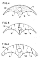
- FIG. 4 represents a peripheral rubber part 5B.
- the latter is pierced with the longitudinal hole 6B for the passage of the tightening bolt, and comprises an external self-cutting annular element 12.
- Its internal side comprises two concave zones 13, 14 with a radius of curvature corresponding substantially to the radius of the internal tubes. It is provided in a central sector with a notch leaving a thin thickness of material (part shown in broken lines), and on both sides of notches extending over its entire height, so as to allow removal by tearing a peripheral zone to adapt the part to an external tube of smaller diameter.
- FIG. 5 represents an internal flange 7B, provided with its tapped hole 8B for receiving the tightening bolt. It also has two zones facing the axis of the outer tube concaves 15, 16 of radius of curvature corresponding substantially to the radius of the internal tubes.
- the external flange 9B shown in FIG. 6 is pierced with a hole 10B for the passage of the tightening bolt, and its side facing the axis of the internal tube has two concave zones 17, 18 intended to receive the internal tubes, and of radius of curvature corresponding substantially to the radius thereof.
- the assembly of the seal is carried out as follows.
- the peripheral parts 5A, 5B, 5C are assembled with their internal flanges 7A, 7B, 7C and external 9A, 9B, 9C by threading the screws 11A, 11B, 11C into the longitudinal holes of the external flanges and peripheral parts. by hand in the holes while tapped on the internal flanges.
- the three assemblies formed by these parts are introduced into the outer tube 1 and around the inner tubes 2A, 2B, 2C.
- the axial part 4 is introduced between the three internal tubes.
- the three screws 11A, 11B, 11C are screwed alternately and successively with a few threads to ensure balanced tightening of the peripheral parts and of the axial part.
- a limit value is preferably fixed for the final tightening torque to ensure the desired degree of tightness, or the tightening is limited by the length of the screw thread.
- the device of the invention can be adapted to a number of internal tubes or rods greater than 3, the number of peripheral parts then being equal to the number of internal tubes or rods.
Landscapes
- Engineering & Computer Science (AREA)
- General Engineering & Computer Science (AREA)
- Mechanical Engineering (AREA)
- Gasket Seals (AREA)
- Joints Allowing Movement (AREA)
Applications Claiming Priority (2)
| Application Number | Priority Date | Filing Date | Title |
|---|---|---|---|
| FR8712606A FR2620506B1 (fr) | 1987-09-11 | 1987-09-11 | Joint a diametres variables pour etancheite entre un tube ou orifice externe et des tubes ou tiges internes |
| FR8712606 | 1987-09-11 |
Publications (2)
| Publication Number | Publication Date |
|---|---|
| EP0307780A1 true EP0307780A1 (de) | 1989-03-22 |
| EP0307780B1 EP0307780B1 (de) | 1993-07-21 |
Family
ID=9354806
Family Applications (1)
| Application Number | Title | Priority Date | Filing Date |
|---|---|---|---|
| EP19880114600 Expired - Lifetime EP0307780B1 (de) | 1987-09-11 | 1988-09-07 | Dichtung mit variablen Durchmessern für die Abdichtung zwischen einem äusseren Rohr und inneren Rohren oder Stangen |
Country Status (4)
| Country | Link |
|---|---|
| EP (1) | EP0307780B1 (de) |
| DE (1) | DE3882467T2 (de) |
| ES (1) | ES2041752T3 (de) |
| FR (1) | FR2620506B1 (de) |
Cited By (6)
| Publication number | Priority date | Publication date | Assignee | Title |
|---|---|---|---|---|
| FR2650049A1 (fr) * | 1989-07-18 | 1991-01-25 | Tyerman David | Dispositif de blocage dans un conduit tubulaire, notamment dans un tube pour cables |
| GB2262392A (en) * | 1991-12-10 | 1993-06-16 | Jack Moon Co Ltd | An expansion seal for cable pipe |
| US5236227A (en) * | 1991-11-12 | 1993-08-17 | Robert Adams | Assembly for connecting multi-duct conduits having tapered alignment walls |
| US5372388A (en) * | 1993-04-30 | 1994-12-13 | American Pipe & Plastics, Inc. | Integral multi-duct conduit section |
| EP1263106A1 (de) * | 2001-05-21 | 2002-12-04 | Polypipe Civils Limited | Anordnung zum Abdichten eines Rohrs |
| US6866300B2 (en) * | 2002-10-29 | 2005-03-15 | Calsonickansei North America, Inc. | Dual flange for a tube joint assembly |
Families Citing this family (1)
| Publication number | Priority date | Publication date | Assignee | Title |
|---|---|---|---|---|
| US10408365B2 (en) * | 2016-04-21 | 2019-09-10 | O'Brien Holding Co., Inc. | Tubing bundle supports and support systems |
Citations (4)
| Publication number | Priority date | Publication date | Assignee | Title |
|---|---|---|---|---|
| US3655907A (en) * | 1970-10-16 | 1972-04-11 | O Z Electrical Mfg Co Inc | Conduit cable seal |
| DE2209629A1 (de) * | 1972-02-29 | 1973-09-06 | Krone Gmbh | Anordnung zur gasdichten einfuehrung elektrischer kabel in kabelmuffen |
| US4267401A (en) * | 1978-07-03 | 1981-05-12 | Wilkinson William L | Seal plug |
| EP0232180A2 (de) * | 1986-02-06 | 1987-08-12 | RAYCHEM CORPORATION (a Delaware corporation) | In Abschnitte unterteilte Endabdichtung und Verschluss |
-
1987
- 1987-09-11 FR FR8712606A patent/FR2620506B1/fr not_active Expired
-
1988
- 1988-09-07 ES ES88114600T patent/ES2041752T3/es not_active Expired - Lifetime
- 1988-09-07 DE DE19883882467 patent/DE3882467T2/de not_active Expired - Fee Related
- 1988-09-07 EP EP19880114600 patent/EP0307780B1/de not_active Expired - Lifetime
Patent Citations (4)
| Publication number | Priority date | Publication date | Assignee | Title |
|---|---|---|---|---|
| US3655907A (en) * | 1970-10-16 | 1972-04-11 | O Z Electrical Mfg Co Inc | Conduit cable seal |
| DE2209629A1 (de) * | 1972-02-29 | 1973-09-06 | Krone Gmbh | Anordnung zur gasdichten einfuehrung elektrischer kabel in kabelmuffen |
| US4267401A (en) * | 1978-07-03 | 1981-05-12 | Wilkinson William L | Seal plug |
| EP0232180A2 (de) * | 1986-02-06 | 1987-08-12 | RAYCHEM CORPORATION (a Delaware corporation) | In Abschnitte unterteilte Endabdichtung und Verschluss |
Cited By (7)
| Publication number | Priority date | Publication date | Assignee | Title |
|---|---|---|---|---|
| FR2650049A1 (fr) * | 1989-07-18 | 1991-01-25 | Tyerman David | Dispositif de blocage dans un conduit tubulaire, notamment dans un tube pour cables |
| US5236227A (en) * | 1991-11-12 | 1993-08-17 | Robert Adams | Assembly for connecting multi-duct conduits having tapered alignment walls |
| GB2262392A (en) * | 1991-12-10 | 1993-06-16 | Jack Moon Co Ltd | An expansion seal for cable pipe |
| GB2262392B (en) * | 1991-12-10 | 1996-02-28 | Jack Moon Co Ltd | An expansion seal for cable pipe |
| US5372388A (en) * | 1993-04-30 | 1994-12-13 | American Pipe & Plastics, Inc. | Integral multi-duct conduit section |
| EP1263106A1 (de) * | 2001-05-21 | 2002-12-04 | Polypipe Civils Limited | Anordnung zum Abdichten eines Rohrs |
| US6866300B2 (en) * | 2002-10-29 | 2005-03-15 | Calsonickansei North America, Inc. | Dual flange for a tube joint assembly |
Also Published As
| Publication number | Publication date |
|---|---|
| ES2041752T3 (es) | 1993-12-01 |
| FR2620506B1 (fr) | 1989-12-01 |
| DE3882467T2 (de) | 1993-11-11 |
| DE3882467D1 (de) | 1993-08-26 |
| FR2620506A1 (fr) | 1989-03-17 |
| EP0307780B1 (de) | 1993-07-21 |
Similar Documents
| Publication | Publication Date | Title |
|---|---|---|
| EP1110023B1 (de) | Abgedichtete kupplung mit verstellbarer geometrie | |
| EP1872043B1 (de) | Röhrenförmige verbindung mit variablem winkel | |
| EP3553331B1 (de) | Verbindungsvorrichtung, die zwischen mindestens zwei teilen schwenkbar ist, luftfahrzeug, das eine abdeckung umfasst, die mit dieser schwenkbaren verbindungsvorrichtung ausgestattet ist | |
| FR2947592A1 (fr) | Dispositif de liaison mecanique d'au moins deux pieces a alesages coaxiaux | |
| FR2694791A1 (fr) | Ecrous, vis et corps de boulon de sécurité. | |
| US20170268706A1 (en) | High-pressure resistant screw connection for pipe or hose lines with a tapered thread | |
| EP1921362A1 (de) | Doppelspannschelle und Montageverfahren | |
| EP0307780B1 (de) | Dichtung mit variablen Durchmessern für die Abdichtung zwischen einem äusseren Rohr und inneren Rohren oder Stangen | |
| FR2533169A1 (fr) | Ensemble de fixation pour des roues fixees par serrage | |
| FR2724699A1 (fr) | Ecrou | |
| FR2743613A1 (fr) | Entretoise pour le soudage d'un tube a un raccord | |
| EP1413815A1 (de) | Kupplung für zwei Rohre mit aufgeweiteten Enden | |
| EP4295070B1 (de) | Dichtungs- und verriegelungsanordnung für eine flexible rohrverbindung | |
| FR3100293A1 (fr) | Boulon équipé d’un système de blocage en rotation procurant une immobilisation en rotation précise | |
| EP1605195B1 (de) | Rohrkupplungssystem und dazu gehöriges Montageverfahren | |
| WO2000031846A1 (fr) | Presse-etoupe a garniture d'etancheite et dents de serrage epaisses | |
| CH628128A5 (fr) | Raccord de tuyau. | |
| EP1254391A1 (de) | Fixierungsschlauch für faseroptische kabel | |
| EP0307327A1 (de) | Schraubverbindungensvorrichtung für zwei Elemente mit der Möglichkeit den Abstand dazwischen einzustellen | |
| EP4155567B1 (de) | Anschlagring für die kugeln eines kugelgleichlaufgelenks mit einem dichtungsbalg | |
| FR2741916A1 (fr) | Dispositif de premontage et de retenue d'une vis associee a une piece d'assemblage | |
| EP0290312B1 (de) | Explosionsgeschützte Kabeleinführung | |
| FR2966551A1 (fr) | Raccord du type anti-devissage et anti-deboitement, en particulier pour le raccordement de tubes. | |
| FR3111170A3 (fr) | Boulon équipé d’un système de blocage en rotation procurant une immobilisation en rotation précise | |
| CH720834B1 (fr) | Écrou central de roue pour véhicule automobile |
Legal Events
| Date | Code | Title | Description |
|---|---|---|---|
| PUAI | Public reference made under article 153(3) epc to a published international application that has entered the european phase |
Free format text: ORIGINAL CODE: 0009012 |
|
| AK | Designated contracting states |
Kind code of ref document: A1 Designated state(s): BE DE ES FR GB GR IT LU NL |
|
| 17P | Request for examination filed |
Effective date: 19890913 |
|
| 17Q | First examination report despatched |
Effective date: 19901004 |
|
| GRAA | (expected) grant |
Free format text: ORIGINAL CODE: 0009210 |
|
| AK | Designated contracting states |
Kind code of ref document: B1 Designated state(s): BE DE ES FR GB GR IT LU NL |
|
| REF | Corresponds to: |
Ref document number: 3882467 Country of ref document: DE Date of ref document: 19930826 |
|
| ITF | It: translation for a ep patent filed | ||
| GBT | Gb: translation of ep patent filed (gb section 77(6)(a)/1977) |
Effective date: 19930913 |
|
| REG | Reference to a national code |
Ref country code: ES Ref legal event code: FG2A Ref document number: 2041752 Country of ref document: ES Kind code of ref document: T3 |
|
| EPTA | Lu: last paid annual fee | ||
| REG | Reference to a national code |
Ref country code: GR Ref legal event code: FG4A Free format text: 3009418 |
|
| PLBE | No opposition filed within time limit |
Free format text: ORIGINAL CODE: 0009261 |
|
| STAA | Information on the status of an ep patent application or granted ep patent |
Free format text: STATUS: NO OPPOSITION FILED WITHIN TIME LIMIT |
|
| 26N | No opposition filed | ||
| PGFP | Annual fee paid to national office [announced via postgrant information from national office to epo] |
Ref country code: LU Payment date: 19980611 Year of fee payment: 11 |
|
| PGFP | Annual fee paid to national office [announced via postgrant information from national office to epo] |
Ref country code: BE Payment date: 19980713 Year of fee payment: 11 |
|
| PGFP | Annual fee paid to national office [announced via postgrant information from national office to epo] |
Ref country code: GB Payment date: 19980811 Year of fee payment: 11 |
|
| PGFP | Annual fee paid to national office [announced via postgrant information from national office to epo] |
Ref country code: ES Payment date: 19980910 Year of fee payment: 11 |
|
| PGFP | Annual fee paid to national office [announced via postgrant information from national office to epo] |
Ref country code: FR Payment date: 19980918 Year of fee payment: 11 |
|
| PGFP | Annual fee paid to national office [announced via postgrant information from national office to epo] |
Ref country code: GR Payment date: 19980925 Year of fee payment: 11 |
|
| PGFP | Annual fee paid to national office [announced via postgrant information from national office to epo] |
Ref country code: NL Payment date: 19980930 Year of fee payment: 11 |
|
| PG25 | Lapsed in a contracting state [announced via postgrant information from national office to epo] |
Ref country code: LU Free format text: LAPSE BECAUSE OF NON-PAYMENT OF DUE FEES Effective date: 19990907 Ref country code: GB Free format text: LAPSE BECAUSE OF NON-PAYMENT OF DUE FEES Effective date: 19990907 |
|
| PG25 | Lapsed in a contracting state [announced via postgrant information from national office to epo] |
Ref country code: ES Free format text: LAPSE BECAUSE OF NON-PAYMENT OF DUE FEES Effective date: 19990908 |
|
| PGFP | Annual fee paid to national office [announced via postgrant information from national office to epo] |
Ref country code: DE Payment date: 19990924 Year of fee payment: 12 |
|
| PG25 | Lapsed in a contracting state [announced via postgrant information from national office to epo] |
Ref country code: GR Free format text: LAPSE BECAUSE OF NON-PAYMENT OF DUE FEES Effective date: 19990930 Ref country code: BE Free format text: LAPSE BECAUSE OF NON-PAYMENT OF DUE FEES Effective date: 19990930 |
|
| BERE | Be: lapsed |
Owner name: LE JOINT FRANCAIS Effective date: 19990930 |
|
| PG25 | Lapsed in a contracting state [announced via postgrant information from national office to epo] |
Ref country code: NL Free format text: LAPSE BECAUSE OF NON-PAYMENT OF DUE FEES Effective date: 20000401 |
|
| GBPC | Gb: european patent ceased through non-payment of renewal fee |
Effective date: 19990907 |
|
| PG25 | Lapsed in a contracting state [announced via postgrant information from national office to epo] |
Ref country code: FR Free format text: LAPSE BECAUSE OF NON-PAYMENT OF DUE FEES Effective date: 20000531 |
|
| NLV4 | Nl: lapsed or anulled due to non-payment of the annual fee |
Effective date: 20000401 |
|
| REG | Reference to a national code |
Ref country code: FR Ref legal event code: ST |
|
| PG25 | Lapsed in a contracting state [announced via postgrant information from national office to epo] |
Ref country code: DE Free format text: LAPSE BECAUSE OF NON-PAYMENT OF DUE FEES Effective date: 20010601 |
|
| REG | Reference to a national code |
Ref country code: ES Ref legal event code: FD2A Effective date: 20001013 |
|
| PG25 | Lapsed in a contracting state [announced via postgrant information from national office to epo] |
Ref country code: IT Free format text: LAPSE BECAUSE OF NON-PAYMENT OF DUE FEES;WARNING: LAPSES OF ITALIAN PATENTS WITH EFFECTIVE DATE BEFORE 2007 MAY HAVE OCCURRED AT ANY TIME BEFORE 2007. THE CORRECT EFFECTIVE DATE MAY BE DIFFERENT FROM THE ONE RECORDED. Effective date: 20050907 |