EP0307796A1 - Blendschutzbake - Google Patents
Blendschutzbake Download PDFInfo
- Publication number
- EP0307796A1 EP0307796A1 EP88114670A EP88114670A EP0307796A1 EP 0307796 A1 EP0307796 A1 EP 0307796A1 EP 88114670 A EP88114670 A EP 88114670A EP 88114670 A EP88114670 A EP 88114670A EP 0307796 A1 EP0307796 A1 EP 0307796A1
- Authority
- EP
- European Patent Office
- Prior art keywords
- glare
- beacon
- profile
- base plate
- adhesive
- Prior art date
- Legal status (The legal status is an assumption and is not a legal conclusion. Google has not performed a legal analysis and makes no representation as to the accuracy of the status listed.)
- Withdrawn
Links
- 239000000853 adhesive Substances 0.000 claims abstract description 10
- 230000001070 adhesive effect Effects 0.000 claims abstract description 10
- NJPPVKZQTLUDBO-UHFFFAOYSA-N novaluron Chemical compound C1=C(Cl)C(OC(F)(F)C(OC(F)(F)F)F)=CC=C1NC(=O)NC(=O)C1=C(F)C=CC=C1F NJPPVKZQTLUDBO-UHFFFAOYSA-N 0.000 abstract 2
- 230000004313 glare Effects 0.000 description 7
- 229920001169 thermoplastic Polymers 0.000 description 4
- 238000002347 injection Methods 0.000 description 3
- 239000007924 injection Substances 0.000 description 3
- 239000004416 thermosoftening plastic Substances 0.000 description 3
- 239000002184 metal Substances 0.000 description 2
- 230000001154 acute effect Effects 0.000 description 1
- 230000002411 adverse Effects 0.000 description 1
- 238000010276 construction Methods 0.000 description 1
- 230000007797 corrosion Effects 0.000 description 1
- 238000005260 corrosion Methods 0.000 description 1
- 238000005553 drilling Methods 0.000 description 1
- 238000001125 extrusion Methods 0.000 description 1
- 238000009434 installation Methods 0.000 description 1
- 230000002787 reinforcement Effects 0.000 description 1
- 230000006641 stabilisation Effects 0.000 description 1
- 238000011105 stabilization Methods 0.000 description 1
Images
Classifications
-
- E—FIXED CONSTRUCTIONS
- E01—CONSTRUCTION OF ROADS, RAILWAYS, OR BRIDGES
- E01D—CONSTRUCTION OF BRIDGES, ELEVATED ROADWAYS OR VIADUCTS; ASSEMBLY OF BRIDGES
- E01D19/00—Structural or constructional details of bridges
- E01D19/10—Railings; Protectors against smoke or gases, e.g. of locomotives; Maintenance travellers; Fastening of pipes or cables to bridges
- E01D19/103—Parapets, railings ; Guard barriers or road-bridges
-
- E—FIXED CONSTRUCTIONS
- E01—CONSTRUCTION OF ROADS, RAILWAYS, OR BRIDGES
- E01F—ADDITIONAL WORK, SUCH AS EQUIPPING ROADS OR THE CONSTRUCTION OF PLATFORMS, HELICOPTER LANDING STAGES, SIGNS, SNOW FENCES, OR THE LIKE
- E01F7/00—Devices affording protection against snow, sand drifts, side-wind effects, snowslides, avalanches or falling rocks; Anti-dazzle arrangements ; Sight-screens for roads, e.g. to mask accident site
- E01F7/06—Anti-dazzle arrangements ; Securing anti-dazzle means to crash-barriers
Definitions
- the invention relates to an anti-glare beacon.
- Such a glare protection beacon is used in particular on the median of roads with separate lanes.
- the installation of the anti-glare beacon on parapets of bridges is difficult. Because it has been shown that drilling into the parapets to fix the glare shield leads to corrosion damage in the parapet. In particular, the concrete and above all the reinforcement is adversely affected.
- the object of the invention is such a design of a glare protection beacon that the same can be securely attached to a concrete base without affecting the concrete base.
- At least one anti-glare profile with a Z-shaped cross-section sits on a base plate with an underside designed to hold an adhesive.
- the invention differs from the prior art in that the adhesive connection in no way affects the concrete.
- the glare protection beacon is firmly connected to the parapet or concrete base by the adhesive connection, so that it meets all requirements.
- the anti-glare beacon can have a desired height.
- the legs of the anti-glare profile on the one hand provide particularly complete anti-glare protection and on the other hand increase stability.
- the legs in particular cause a large coverage of the apparent cross section.
- An additional stabilization of the anti-glare beacon is achieved in that the anti-glare profile is supported by an angle bracket Base plate is supported.
- the parts of the anti-glare beacon are made of thermoplastic plastic or bent sheet metal parts or rolled profiles.
- the parts can be designed as injection molded parts.
- the strength of the connection of the individual parts is achieved in that the parts are connected to one another by welded connections or adhesive connections.
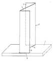
- the anti-glare beacon according to the invention comprises a base plate 1 in the form of a thermoplastic injection molded part, a stamped part made of a sheet metal plate or a rolled profile.
- the underside of the base plate can be flat or have depressions for receiving an adhesive.
- the top of the base plate is flat.
- An anti-glare profile 2 has a Z-shaped cross section and thus has two legs 3 oriented parallel to one another on the longitudinal sides.
- the central web 4 of the glare protection profile is inclined at an acute angle with respect to each leg 3.
- the base plate 1, the anti-glare profile 2 and the support bracket 3 are each designed as thermoplastic injection molded parts or thermoplastic extrusion parts or bent punched parts or strip sections.
- the anti-glare profile 2 and the support bracket 5 are connected to the base plate 1 by means of welded connections 6 or adhesive connections, as is indicated in the drawing.
- the legs 3 result in a high stiffening of the structure. Support brackets (not shown) can be provided for additional stiffening.
- the glare protection profile 2 can be kept in the desired width and at different heights, as this corresponds to the requirements for glare protection.
- the base plate 1 is of such a size that a stable fixing of the anti-glare profile 2 is ensured.
- the anti-glare beacon is glued to a concrete base or parapet with an appropriate adhesive. It can therefore be attached to any point on a parapet without special aids or other elements.
Landscapes
- Engineering & Computer Science (AREA)
- Architecture (AREA)
- Civil Engineering (AREA)
- Structural Engineering (AREA)
- Aiming, Guidance, Guns With A Light Source, Armor, Camouflage, And Targets (AREA)
- Bridges Or Land Bridges (AREA)
Abstract
Eine Blendschutzbake. Das technische Prbolem ist eine solche Ausildung einer Blendschutzbake, daß dieselbe auf einem Betonsockel stabil befestigt werden kann, ohne den Betonsockel zu beeinträchtigen. Auf einer Grundplatte (1) mit einer zur Aufnahme eines Klebstoffes ausgebildeten Unterseite sitzt mindestens ein Blendschutzprofil (2) mit Z-förmigem Querschnitt.
Description
- Die Erfindung betrifft eine Blendschutzbake.
- Eine derartige Blendschutzbake findet insbesondere auf dem Mittelstreifen von Straßen mit getrennten Fahrbahnen Anwendung. Die Anbringung der Blendschutzbake auf Brüstungen von Brücken bereitet Schwierigkeiten. Denn es hat sich gezeigt, daß das Anbohren der Brüstungen zur Befestigung der Blendschutzbake zu Korrosionsschäden in der Brüstung führt. Insbesondere wird der Beton und vor allem die Armierung beeinträchtigt.
- Aufgabe der Erfindung ist eine solche Ausbildung einer Blendschutzbake, daß dieselbe auf einem Betonsockel stabil befestigt werden kann, ohne den Betonsockel zu beeinträchtigen.
- Diese Aufgabe wird nach der Erfindung dadurch gelöst, daß auf einer Grundplatte mit einer zur Aufnahme eines Klebstoffes ausgebildeten Unterseite mindestens ein Blendschutzprofil mit Z-förmigem Querschnitt sitzt.
- Die Erfindung unterscheidet sich insofern vom Stand der Technik, als die Klebeverbindung den Beton in keiner Weise beeinträchtigt. Die Blendschutzbake ist durch die Klebeverbindung fest mit der Brüstung bzw. dem Betonsockel verbunden, so daß sie allen Anforderungen gerecht wird. Die Blendschutzbake kann eine jeweils gewünschte Höhe aufweisen.
- Die Schenkel des Blendschutzprofils bewirken einerseits einen besonders vollständigen Blendschutz und erhöhen andererseits die Stabilität. Die Schenkel bewirken insbesondere eine große Überdeckung des scheinbaren Querschnitts.
- Eine zusätzliche Stabilisierung der Blendschutzbake wird dadurch erzielt, daß das Blendschutzprofil durch Stützwinkel gegenüber der Grundplatte abgestützt ist.
- Die Teile der Blendschutzbake bestehen aus thermoplastischem Kunststoff oder aus Blechbiegeteilen oder Walzprofilen. Die Teile können als Spritzgießteile ausgebildet sein.
- Die Festigkeit der Verbindung der Einzelteile wird dadurch erreicht, daß die Teile durch Schweißverbindungen oder Klebeverbindungen miteinander verbunden sind.
- Eine Ausführungsform der Erfindung wird im Folgenden unter Bezugnahme auf die anliegende Zeichnung erläutert, die eine schematische Ansicht einer Blendschutzbake zeigt.
- Die Blendschutzbake nach der Erfindung umfaßt eine Grundplatte 1 in Form eines Thermoplastspritzgießteiles, eines Stanzteils aus einer Blechplatte oder eines Walzprofils. Die Unterseite der Grundplatte kann eben ausgebildet sein oder Vertiefungen zur Aufnahme eines Klebstoffes aufweisen. Die Oberseite der Grundplatte ist eben.
- Ein Blendschutzprofil 2 hat einen Z-förmigen Querschnitt und weist somit an den Längsseiten zwei parallel zueinander ausgerichtete Schenkel 3 auf. Der Mittelsteg 4 des Blendschutzprofils ist jeweils unter einem spitzen Winkel gegenüber jedem Schenkel 3 geneigt.
- Die Grundplatte 1, das Blendschutzprofil 2 und der Stützwinkel 3 sind jeweils als Thermoplastspritzgießteile oder Thermoplastextrusionsteile bzw. abgekantete Stanzteile oder Bandabschnitte ausgebildet. Das Blendschutzprofil 2 und die Stützwinkel 5 sind mit der Grundplatte 1 durch Schweißverbindungen 6 oder Klebeverbindungen verbunden, wie dies in der Zeichnung angedeutet ist. Die Schenkel 3 ergeben eine hohe Aussteifung des Aufbaus. Zur zusätzlichen Aussteifung kann man nicht dargestellte Stützwinkel vorsehen.
- Das Blendschutzprofil 2 kann in der jeweils gewünschten Breite und in unterschiedlichen Höhen bereitgehalten werden, wie dies den Anforderungen für den Blendschutz entspricht. Die Grundplatte 1 hat eine solche Größe, daß eine stabile Festlegung des Blendschutzprofils 2 gewährleistet ist.
- Die Blendschutzbake wird mit einem entsprechenden Klebstoff auf einen Betonsockel oder eine Brüstung aufgeklebt. Sie kann somit an jeder Stelle einer Brückenbrüstung ohne besondere Hilfsmittel oder andere Elemente angebracht werden.
- Man kann auf einer Grundplatte auch mehrere Blendschutzprofile vorsehen. Die einzelne Blenschutzbake wird dadurch länger, so daß sich bei der Montage auf der Baustelle Vorteile ergeben. Denn die An zahl der zu montierenden Blendschutzbaken wird infolge ihrer größeren Länge kleiner.
Claims (4)
1. Blendschutzbake, dadurch gekennzeichnet, daß auf einer Grundplatte (1) mit einer zur Aufnahme eines Klebstoffes ausgebildeten Unterseite mindestens ein Blendschutzprofil (2) mit Z-förmigem Querschnitt sitzt.
2. Blendschutzbake nach Anspruch 1, dadurch gekennzeichnet, daß das Blendschutzprofil (2) durch Stützwinkel (5) gegenüber der Grundplatte (1) abgestützt ist.
3. Blendschutzbake nach Anspruch 1 oder 2, dadurch gekennzeichnet, daß die Teile durch Schweißverbindungen oder Klebeverbindungen miteinander verbunden sind.
4. Blendschutzprofil nach einem der Ansprüche 1 bis 3, dadurch gekennzeichnet, daß auf der Grundplatte (1) mehrere Blendschutzprofile angeordnet sind.
Applications Claiming Priority (2)
| Application Number | Priority Date | Filing Date | Title |
|---|---|---|---|
| DE8712157U DE8712157U1 (de) | 1987-09-08 | 1987-09-08 | Blendschutzbake |
| DE8712157U | 1987-09-08 |
Publications (1)
| Publication Number | Publication Date |
|---|---|
| EP0307796A1 true EP0307796A1 (de) | 1989-03-22 |
Family
ID=6811879
Family Applications (1)
| Application Number | Title | Priority Date | Filing Date |
|---|---|---|---|
| EP88114670A Withdrawn EP0307796A1 (de) | 1987-09-08 | 1988-09-08 | Blendschutzbake |
Country Status (2)
| Country | Link |
|---|---|
| EP (1) | EP0307796A1 (de) |
| DE (1) | DE8712157U1 (de) |
Cited By (4)
| Publication number | Priority date | Publication date | Assignee | Title |
|---|---|---|---|---|
| WO2010105307A1 (en) * | 2009-03-19 | 2010-09-23 | Industrial Galvanizers Corporation Pty Ltd | Improved road barrier |
| US9631331B2 (en) | 2011-05-30 | 2017-04-25 | Industrial Galvanizers Corporation Pty Ltd | Barrier construction |
| US10570641B2 (en) | 2015-11-27 | 2020-02-25 | Industrial Galvanizers Corporation Pty Ltd | Parking barrier system and post |
| US11371198B2 (en) | 2018-07-26 | 2022-06-28 | Industrial Galvanizers Corporation Pty Ltd | Spacer piece for a guard rail system |
Citations (5)
| Publication number | Priority date | Publication date | Assignee | Title |
|---|---|---|---|---|
| DE1534556A1 (de) * | 1966-04-30 | 1969-10-09 | Ries Adolf | Sicherheitsblende fuer Strassen und Autobahnen |
| DE1941602A1 (de) * | 1969-08-16 | 1971-02-25 | Pfaffenberg Gmbh | Blendschutzvorrichtung fuer Strassen |
| US4224002A (en) * | 1978-08-04 | 1980-09-23 | Amerace Corporation | Highway delineator |
| US4338041A (en) * | 1981-01-12 | 1982-07-06 | Schmanski Donald W | Glarefoil assembly |
| EP0118323A1 (de) * | 1983-02-04 | 1984-09-12 | MATERIELS ET APPLICATIONS DE SECURITE POUR LES AEROPORTS, l'INDUSTRIE ET LES ROUTES (MASAIR) | An Fahrbahnteilern aus Beton anbringbare Vorrichtung zu deren Schutz und Sichtbarmachung |
Family Cites Families (3)
| Publication number | Priority date | Publication date | Assignee | Title |
|---|---|---|---|---|
| DE7301288U (de) * | 1973-05-03 | Kunststoffwerk Philippine Gmbh & Co Kg | Blendschutzzaun fur Autostraßen | |
| DE1967751U (de) * | 1967-06-02 | 1967-09-07 | Margret Gross | Lamelle fuer einen autobahn-blendschutzzaun. |
| GB1258315A (de) * | 1968-03-04 | 1971-12-30 |
-
1987
- 1987-09-08 DE DE8712157U patent/DE8712157U1/de not_active Expired
-
1988
- 1988-09-08 EP EP88114670A patent/EP0307796A1/de not_active Withdrawn
Patent Citations (5)
| Publication number | Priority date | Publication date | Assignee | Title |
|---|---|---|---|---|
| DE1534556A1 (de) * | 1966-04-30 | 1969-10-09 | Ries Adolf | Sicherheitsblende fuer Strassen und Autobahnen |
| DE1941602A1 (de) * | 1969-08-16 | 1971-02-25 | Pfaffenberg Gmbh | Blendschutzvorrichtung fuer Strassen |
| US4224002A (en) * | 1978-08-04 | 1980-09-23 | Amerace Corporation | Highway delineator |
| US4338041A (en) * | 1981-01-12 | 1982-07-06 | Schmanski Donald W | Glarefoil assembly |
| EP0118323A1 (de) * | 1983-02-04 | 1984-09-12 | MATERIELS ET APPLICATIONS DE SECURITE POUR LES AEROPORTS, l'INDUSTRIE ET LES ROUTES (MASAIR) | An Fahrbahnteilern aus Beton anbringbare Vorrichtung zu deren Schutz und Sichtbarmachung |
Cited By (12)
| Publication number | Priority date | Publication date | Assignee | Title |
|---|---|---|---|---|
| WO2010105307A1 (en) * | 2009-03-19 | 2010-09-23 | Industrial Galvanizers Corporation Pty Ltd | Improved road barrier |
| CN102439231A (zh) * | 2009-03-19 | 2012-05-02 | 工业镀锌私人有限公司 | 改进的道路障碍 |
| JP2012520952A (ja) * | 2009-03-19 | 2012-09-10 | インダストリアル ガルヴァナイザーズ コーポレーション ピーティーワイ リミテッド | 改良道路バリア |
| US8858112B2 (en) | 2009-03-19 | 2014-10-14 | Industrial Galvanizers Corporation Pty Ltd | Road barrier |
| CN102439231B (zh) * | 2009-03-19 | 2015-06-10 | 工业镀锌私人有限公司 | 改进的道路障碍 |
| US10501902B2 (en) | 2009-03-19 | 2019-12-10 | Industrial Galvanizers Corporation Pty Ltd | Road barrier |
| US9631331B2 (en) | 2011-05-30 | 2017-04-25 | Industrial Galvanizers Corporation Pty Ltd | Barrier construction |
| US10329722B2 (en) | 2011-05-30 | 2019-06-25 | Industrial Galvanizers Corporation Pty Ltd. | Barrier Construction |
| US10544554B2 (en) | 2011-05-30 | 2020-01-28 | Industrial Galvanizers Corporation Pty Ltd. | Barrier construction |
| US11434613B2 (en) | 2011-05-30 | 2022-09-06 | Industrial Galvanizers Corporation Pty Ltd. | Barrier construction |
| US10570641B2 (en) | 2015-11-27 | 2020-02-25 | Industrial Galvanizers Corporation Pty Ltd | Parking barrier system and post |
| US11371198B2 (en) | 2018-07-26 | 2022-06-28 | Industrial Galvanizers Corporation Pty Ltd | Spacer piece for a guard rail system |
Also Published As
| Publication number | Publication date |
|---|---|
| DE8712157U1 (de) | 1987-10-29 |
Similar Documents
| Publication | Publication Date | Title |
|---|---|---|
| DE69919129T2 (de) | Hängedecke | |
| DE202020104196U1 (de) | Baugerüst | |
| EP1310613A2 (de) | Halterung für eine Abdeckleiste | |
| EP0307796A1 (de) | Blendschutzbake | |
| DE3729824C2 (de) | ||
| DE3016586A1 (de) | Basisstuetze fuer ein baugeruest | |
| DE2601136C2 (de) | Hauseingangsüberdachung | |
| EP0383240B1 (de) | Hohlraum Montage Boden | |
| DE2060394A1 (de) | Decke zur Verbesserung der Akustik | |
| EP0639682B1 (de) | Ankerbügel für U-Profilschienen | |
| DE2921480C2 (de) | ||
| EP4617432B1 (de) | Gesimsschalungstrageinheit | |
| DE3338558C2 (de) | ||
| DE10121991C2 (de) | Abhänger für abgehängte Decken oder leichte Unterdecken | |
| DE20013958U1 (de) | Schalungselement für Betonarbeiten | |
| DE202010002635U1 (de) | Stützauflage für eine mit Gefälle zu montierende Mauerabdeckung | |
| DE202024002500U1 (de) | Gesimsschalungstrageinheit | |
| DE102017127941B4 (de) | Anordnung zur betonlosen Befestigung rohrförmiger Aufbauten | |
| DE2919183A1 (de) | Einrichtung zur festlegung von sonnenkollektoren | |
| DE19653363A1 (de) | Verbreiterungskonsole zur Befestigung an Gerüsten | |
| DE8535734U1 (de) | Deckenkassettenclip | |
| DE8812369U1 (de) | Auflage- und Befestigungsvorrichtung für Dacheinläufe | |
| DE2952034A1 (de) | Sichtzeichen zur kennlichmachung von fahrbahnabweichungen | |
| DE9416581U1 (de) | Wandanker | |
| DE10123319A1 (de) | Randabschluß an Gebäudedecken |
Legal Events
| Date | Code | Title | Description |
|---|---|---|---|
| PUAI | Public reference made under article 153(3) epc to a published international application that has entered the european phase |
Free format text: ORIGINAL CODE: 0009012 |
|
| AK | Designated contracting states |
Kind code of ref document: A1 Designated state(s): AT BE CH DE ES FR GB GR IT LI LU NL SE |
|
| RBV | Designated contracting states (corrected) |
Designated state(s): AT BE CH DE ES FR GB IT LI NL SE |
|
| 17P | Request for examination filed |
Effective date: 19890919 |
|
| STAA | Information on the status of an ep patent application or granted ep patent |
Free format text: STATUS: THE APPLICATION IS DEEMED TO BE WITHDRAWN |
|
| 18D | Application deemed to be withdrawn |
Effective date: 19910403 |