EP0307903A1 - Dispositif pour le blocage rotatif rapide et automatique d'un porte-outil dans un corps de révolution connecté, par exemple à une machine-outil - Google Patents
Dispositif pour le blocage rotatif rapide et automatique d'un porte-outil dans un corps de révolution connecté, par exemple à une machine-outil Download PDFInfo
- Publication number
- EP0307903A1 EP0307903A1 EP88115095A EP88115095A EP0307903A1 EP 0307903 A1 EP0307903 A1 EP 0307903A1 EP 88115095 A EP88115095 A EP 88115095A EP 88115095 A EP88115095 A EP 88115095A EP 0307903 A1 EP0307903 A1 EP 0307903A1
- Authority
- EP
- European Patent Office
- Prior art keywords
- pistons
- tool holder
- tool
- toolholder
- machine tool
- Prior art date
- Legal status (The legal status is an assumption and is not a legal conclusion. Google has not performed a legal analysis and makes no representation as to the accuracy of the status listed.)
- Granted
Links
- 230000008878 coupling Effects 0.000 claims description 2
- 238000010168 coupling process Methods 0.000 claims description 2
- 238000005859 coupling reaction Methods 0.000 claims description 2
- 238000003801 milling Methods 0.000 claims description 2
- 230000013011 mating Effects 0.000 claims 1
- 230000002028 premature Effects 0.000 description 2
- 230000006378 damage Effects 0.000 description 1
- 239000013013 elastic material Substances 0.000 description 1
- 239000000463 material Substances 0.000 description 1
Images
Classifications
-
- B—PERFORMING OPERATIONS; TRANSPORTING
- B23—MACHINE TOOLS; METAL-WORKING NOT OTHERWISE PROVIDED FOR
- B23B—TURNING; BORING
- B23B31/00—Chucks; Expansion mandrels; Adaptations thereof for remote control
- B23B31/02—Chucks
- B23B31/10—Chucks characterised by the retaining or gripping devices or their immediate operating means
- B23B31/107—Retention by laterally-acting detents, e.g. pins, screws, wedges; Retention by loose elements, e.g. balls
- B23B31/1075—Retention by screws
- B23B31/1077—Retention by screws acting on a floating pin
-
- B—PERFORMING OPERATIONS; TRANSPORTING
- B23—MACHINE TOOLS; METAL-WORKING NOT OTHERWISE PROVIDED FOR
- B23B—TURNING; BORING
- B23B31/00—Chucks; Expansion mandrels; Adaptations thereof for remote control
- B23B31/02—Chucks
- B23B31/10—Chucks characterised by the retaining or gripping devices or their immediate operating means
- B23B31/12—Chucks with simultaneously-acting jaws, whether or not also individually adjustable
- B23B31/14—Chucks with simultaneously-acting jaws, whether or not also individually adjustable involving the use of centrifugal force
- B23B31/142—To grip a tool or workpiece
-
- B—PERFORMING OPERATIONS; TRANSPORTING
- B23—MACHINE TOOLS; METAL-WORKING NOT OTHERWISE PROVIDED FOR
- B23B—TURNING; BORING
- B23B2226/00—Materials of tools or workpieces not comprising a metal
- B23B2226/33—Elastomers, e.g. rubber
Definitions
- the aim of the present invention is a device for fast and automatic rotating locking of a tool holder in a e.g. with a machine tool or milling machine firmly connected rotating body.
- the device according to the invention is particularly suitable and intended for rotating tools with high and highest speeds.
- the known locking devices show some disadvantages, such as inaccurate centering between the tool holder and the rotating body of the machine, which causes tool vibrations, which leads to premature destruction of the bearing shells and to premature consumption of the cutting edges.
- the locking height of the tool is not ensured with accuracy in the known devices.
- the device according to the invention eliminates the aforementioned disadvantages of the known devices, namely disadvantages that occur in connection with machines with tools intended for rotating at high and highest speeds and become a danger.
- the system of quick and automatic locking not only eliminates vibrations of the tool, but also ensures precise and always uniform locking height of the tool, which is to be regarded as a great advantage for the repeatability of the work.
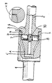
- the system essentially consists of the arrangement of two or more pistons, which are arranged radially opposite one another in the tool holder, and which press with their heads against a ring-shaped part inside the rotary body by centrifugal force.
- the device consists of the rotating body 1 firmly connected to the machine and the tool holder 2 which is to be blocked in the body 1.
- the body 1 has a recess with a first cylindrical section, a second section with a conical widening and a third annular section and an inwardly extending annular end.
- the body 2 has a first cylindrical section, a second conically widening section and a third cylindrical section as well as an annular section which extends outwards.
- the tool holder 2 is guided radially with its first cylindrical section in the first cylindrical section of the body 1 and also with its cylindrical end section in the annular section of the body 1.
- the front ends 3, 4, one directed towards the other, of the annular section of the body 1 and the tool holder 2 determine the coupling height of the tool holder 2 in the body 1.
- two or more cylindrical recesses are provided, radially opposite one another, in each of which there is built-in and radially movable a piston 7, 8 with a bevelled outer head.
- the two pistons 7, 8 are glued with their inner ends to a cross-shaped element 10, which is made of highly elastic material.
- the tool holder 2 thus constructed can be inserted into the body 1 because the elastic member 10 allows the pistons 7, 8 to retract inward first to overcome the internal annular surface of the end portion which is inside of the body 1 protrudes, and then push the two pistons radially with their bevels of the head against the bevels of the annular section of the body 1 so that when the machine tool 2 is stationary, when it is mounted vertically, it does not come out of the body 1 is extractable.
- the cross shape of the elastic element prevents the pistons from falling out when the tool holder is not mounted.
- the pistons 7, 8 When the body 1 is rotating, the pistons 7, 8 are pressed outwards by centrifugal force and their heads are pressed against the inner annular surface of the body 1. In addition, they are pressed with their bevel of the head against the bevel 5 of the identical angle of the annular projection of the body 1 with them.
- the tool holder 2 is easily and quickly coupled in the body 1 and the locking both radially and axially between the two parts takes place quickly and automatically, in contrast to the known devices which require a locking operation with manual operation.
Landscapes
- Engineering & Computer Science (AREA)
- Mechanical Engineering (AREA)
- Jigs For Machine Tools (AREA)
- Gripping On Spindles (AREA)
- Turning (AREA)
Priority Applications (1)
| Application Number | Priority Date | Filing Date | Title |
|---|---|---|---|
| AT88115095T ATE72154T1 (de) | 1987-09-16 | 1988-09-14 | Vorrichtung fuer schnelle und automatische rotierende sperrung eines werkzeughalters in einem rotationskoerper in seiner festen verbindung z. b. mit einer werkzeugmaschine oder fraesmaschine. |
Applications Claiming Priority (2)
| Application Number | Priority Date | Filing Date | Title |
|---|---|---|---|
| IT2192487 | 1987-09-16 | ||
| IT21924/87A IT1222667B (it) | 1987-09-16 | 1987-09-16 | Dispositivo di bloccaggio rotatorio rapido ed automatico di un portautensile in un corpo di rotazione solidale ad esempio ad una macchina utensile o ad una fresatrice |
Publications (2)
| Publication Number | Publication Date |
|---|---|
| EP0307903A1 true EP0307903A1 (fr) | 1989-03-22 |
| EP0307903B1 EP0307903B1 (fr) | 1992-01-29 |
Family
ID=11188863
Family Applications (1)
| Application Number | Title | Priority Date | Filing Date |
|---|---|---|---|
| EP88115095A Expired - Lifetime EP0307903B1 (fr) | 1987-09-16 | 1988-09-14 | Dispositif pour le blocage rotatif rapide et automatique d'un porte-outil dans un corps de révolution connecté, par exemple à une machine-outil |
Country Status (4)
| Country | Link |
|---|---|
| EP (1) | EP0307903B1 (fr) |
| AT (1) | ATE72154T1 (fr) |
| DE (1) | DE3868193D1 (fr) |
| IT (1) | IT1222667B (fr) |
Cited By (2)
| Publication number | Priority date | Publication date | Assignee | Title |
|---|---|---|---|---|
| AU610694B2 (en) * | 1988-02-17 | 1991-05-23 | Sasib Bakery Holland N.V. | Dough piece bending device |
| US8439176B2 (en) | 2008-02-11 | 2013-05-14 | Hh Patent A/S | Coupling |
Citations (5)
| Publication number | Priority date | Publication date | Assignee | Title |
|---|---|---|---|---|
| US2367863A (en) * | 1943-03-26 | 1945-01-23 | Teletype Corp | Centrifugal chuck |
| US3672256A (en) * | 1970-11-09 | 1972-06-27 | Advanced Controls Corp | Centrifugal chuck device |
| US3709508A (en) * | 1970-11-12 | 1973-01-09 | Excellon Ind | Chuck assembly with centrifugal collet |
| GB1345386A (en) * | 1970-05-01 | 1974-01-30 | Digital Systems | Collet |
| US3837661A (en) * | 1972-06-21 | 1974-09-24 | Excellon Ind | Chuck sleeve |
-
1987
- 1987-09-16 IT IT21924/87A patent/IT1222667B/it active
-
1988
- 1988-09-14 DE DE8888115095T patent/DE3868193D1/de not_active Expired - Lifetime
- 1988-09-14 EP EP88115095A patent/EP0307903B1/fr not_active Expired - Lifetime
- 1988-09-14 AT AT88115095T patent/ATE72154T1/de not_active IP Right Cessation
Patent Citations (5)
| Publication number | Priority date | Publication date | Assignee | Title |
|---|---|---|---|---|
| US2367863A (en) * | 1943-03-26 | 1945-01-23 | Teletype Corp | Centrifugal chuck |
| GB1345386A (en) * | 1970-05-01 | 1974-01-30 | Digital Systems | Collet |
| US3672256A (en) * | 1970-11-09 | 1972-06-27 | Advanced Controls Corp | Centrifugal chuck device |
| US3709508A (en) * | 1970-11-12 | 1973-01-09 | Excellon Ind | Chuck assembly with centrifugal collet |
| US3837661A (en) * | 1972-06-21 | 1974-09-24 | Excellon Ind | Chuck sleeve |
Non-Patent Citations (1)
| Title |
|---|
| PATENT ABSTRACTS OF JAPAN, * |
Cited By (2)
| Publication number | Priority date | Publication date | Assignee | Title |
|---|---|---|---|---|
| AU610694B2 (en) * | 1988-02-17 | 1991-05-23 | Sasib Bakery Holland N.V. | Dough piece bending device |
| US8439176B2 (en) | 2008-02-11 | 2013-05-14 | Hh Patent A/S | Coupling |
Also Published As
| Publication number | Publication date |
|---|---|
| DE3868193D1 (de) | 1992-03-12 |
| IT1222667B (it) | 1990-09-12 |
| EP0307903B1 (fr) | 1992-01-29 |
| IT8721924A0 (it) | 1987-09-16 |
| ATE72154T1 (de) | 1992-02-15 |
Similar Documents
| Publication | Publication Date | Title |
|---|---|---|
| EP0668810B1 (fr) | Dispositif de serrage pour machines-outils | |
| DE69515672T2 (de) | Spannzangenfutter mit durch axiale kraft belastetem lager | |
| DE69909262T2 (de) | Messkopf zum Kontrollieren linearer Dimensionen mit einem flachen Dämpfungselement | |
| DE69800037T2 (de) | Spannfutter | |
| DE29508112U1 (de) | Profilmesserkopf | |
| EP0450383B1 (fr) | Dispositif de serrage et de centrage | |
| EP1044760B1 (fr) | Dispositif de serrage | |
| DE69016862T2 (de) | Spannvorrichtung zum Halten einer Kammer zum Zentrifugieren von Blut. | |
| EP2882554B1 (fr) | Dispositif d'équilibrage ou de mesure | |
| DE10336869A1 (de) | Werkzeugkupplung | |
| DE4332506C2 (de) | Präzisionsbohrkopf mit radial beweglichem Werkzeug für die Fertigbearbeitung von Bohrungen | |
| DE102023003155A1 (de) | Bearbeitungssystem | |
| DE3029133C2 (de) | Werkzeughalter | |
| EP0307903A1 (fr) | Dispositif pour le blocage rotatif rapide et automatique d'un porte-outil dans un corps de révolution connecté, par exemple à une machine-outil | |
| DD285478A7 (de) | Werkzeugkupplung, insbesondere fuer rotierende zerspannungswerkzeuge | |
| DE69215905T2 (de) | Spannvorrichtung für fräser oder ähnliche, anpassbar für verschiedene haltergrössen | |
| EP4699740A1 (fr) | Système de serrage rapide | |
| DE3341507C2 (fr) | ||
| DE202023103857U1 (de) | Universelles Spannzangenfutter | |
| DE202010006416U1 (de) | Spannzange | |
| DE2343302C2 (de) | Schleif-, Poliermaschine o.dgl., mit einer von einem druckluftbeaufschlagbaren Laufrad antreibbaren Arbeitsspindel | |
| DE3819181A1 (de) | Fraes- und/oder bohrmaschine mit arbeitsspindelverriegelung | |
| DE1204498B (de) | Mitnehmerspitze fuer Werkzeugmaschinen | |
| DE2062097A1 (de) | Honwerkzeug | |
| DE20219338U1 (de) | Spanneinrichtung zur Befestigung eines Einzugsbolzens mit Nuten |
Legal Events
| Date | Code | Title | Description |
|---|---|---|---|
| PUAI | Public reference made under article 153(3) epc to a published international application that has entered the european phase |
Free format text: ORIGINAL CODE: 0009012 |
|
| AK | Designated contracting states |
Kind code of ref document: A1 Designated state(s): AT CH DE FR LI |
|
| 17P | Request for examination filed |
Effective date: 19890710 |
|
| 17Q | First examination report despatched |
Effective date: 19900927 |
|
| GRAA | (expected) grant |
Free format text: ORIGINAL CODE: 0009210 |
|
| AK | Designated contracting states |
Kind code of ref document: B1 Designated state(s): AT CH DE FR LI |
|
| REF | Corresponds to: |
Ref document number: 72154 Country of ref document: AT Date of ref document: 19920215 Kind code of ref document: T |
|
| REF | Corresponds to: |
Ref document number: 3868193 Country of ref document: DE Date of ref document: 19920312 |
|
| ET | Fr: translation filed | ||
| PLBE | No opposition filed within time limit |
Free format text: ORIGINAL CODE: 0009261 |
|
| STAA | Information on the status of an ep patent application or granted ep patent |
Free format text: STATUS: NO OPPOSITION FILED WITHIN TIME LIMIT |
|
| 26N | No opposition filed | ||
| PGFP | Annual fee paid to national office [announced via postgrant information from national office to epo] |
Ref country code: AT Payment date: 19930917 Year of fee payment: 6 |
|
| PGFP | Annual fee paid to national office [announced via postgrant information from national office to epo] |
Ref country code: FR Payment date: 19930924 Year of fee payment: 6 |
|
| PGFP | Annual fee paid to national office [announced via postgrant information from national office to epo] |
Ref country code: DE Payment date: 19931110 Year of fee payment: 6 |
|
| PGFP | Annual fee paid to national office [announced via postgrant information from national office to epo] |
Ref country code: CH Payment date: 19931222 Year of fee payment: 6 |
|
| PG25 | Lapsed in a contracting state [announced via postgrant information from national office to epo] |
Ref country code: AT Effective date: 19940914 |
|
| PG25 | Lapsed in a contracting state [announced via postgrant information from national office to epo] |
Ref country code: LI Effective date: 19940930 Ref country code: CH Effective date: 19940930 |
|
| PG25 | Lapsed in a contracting state [announced via postgrant information from national office to epo] |
Ref country code: FR Effective date: 19950531 |
|
| REG | Reference to a national code |
Ref country code: CH Ref legal event code: PL |
|
| PG25 | Lapsed in a contracting state [announced via postgrant information from national office to epo] |
Ref country code: DE Effective date: 19950601 |
|
| REG | Reference to a national code |
Ref country code: FR Ref legal event code: ST |