EP0307961A1 - Appareil de nettoyage pour échangeurs de chaleur à faisceaux de tubes, en particulier pour la zone de la plaque tubulaire et de la plaque d'espacement - Google Patents
Appareil de nettoyage pour échangeurs de chaleur à faisceaux de tubes, en particulier pour la zone de la plaque tubulaire et de la plaque d'espacement Download PDFInfo
- Publication number
- EP0307961A1 EP0307961A1 EP88115337A EP88115337A EP0307961A1 EP 0307961 A1 EP0307961 A1 EP 0307961A1 EP 88115337 A EP88115337 A EP 88115337A EP 88115337 A EP88115337 A EP 88115337A EP 0307961 A1 EP0307961 A1 EP 0307961A1
- Authority
- EP
- European Patent Office
- Prior art keywords
- lance
- tube
- cleaning device
- cleaning
- nozzles
- Prior art date
- Legal status (The legal status is an assumption and is not a legal conclusion. Google has not performed a legal analysis and makes no representation as to the accuracy of the status listed.)
- Granted
Links
- 238000004140 cleaning Methods 0.000 title claims abstract description 37
- 125000006850 spacer group Chemical group 0.000 title claims description 6
- 239000012459 cleaning agent Substances 0.000 claims description 6
- 238000007689 inspection Methods 0.000 abstract description 3
- 230000005855 radiation Effects 0.000 description 5
- 239000007921 spray Substances 0.000 description 5
- 238000003780 insertion Methods 0.000 description 3
- 230000037431 insertion Effects 0.000 description 3
- 239000007787 solid Substances 0.000 description 2
- 238000005452 bending Methods 0.000 description 1
- 230000005540 biological transmission Effects 0.000 description 1
- 238000010276 construction Methods 0.000 description 1
- 239000003599 detergent Substances 0.000 description 1
- 238000000034 method Methods 0.000 description 1
- 238000005507 spraying Methods 0.000 description 1
Images

Classifications
-
- F—MECHANICAL ENGINEERING; LIGHTING; HEATING; WEAPONS; BLASTING
- F22—STEAM GENERATION
- F22B—METHODS OF STEAM GENERATION; STEAM BOILERS
- F22B37/00—Component parts or details of steam boilers
- F22B37/02—Component parts or details of steam boilers applicable to more than one kind or type of steam boiler
- F22B37/48—Devices or arrangements for removing water, minerals or sludge from boilers ; Arrangement of cleaning apparatus in boilers; Combinations thereof with boilers
- F22B37/483—Devices or arrangements for removing water, minerals or sludge from boilers ; Arrangement of cleaning apparatus in boilers; Combinations thereof with boilers specially adapted for nuclear steam generators
Definitions
- the invention relates to a cleaning device which is introduced through an opening into a heat exchanger and with which in particular the tube plate and spacer plate area can be cleaned. It relates in particular to a cleaning device for heat exchangers with tube bundles, in particular for the tube sheet and spacer plate area, in which a lance provided with nozzles can be inserted into the tube bundle through an opening of the heat exchanger, can be continued step by step and can be moved by a pivoting device, and in which a flange with a hollow cylinder is provided for guiding the lance and for attachment to the opening.
- a cleaning device is known from US Pat. No. 4,273,076, which is attached to an opening of the heat exchanger by means of a mounting plate in which a lance is guided.
- the lance has a rack-shaped configuration along its upper side, on which a drive acts in such a way that the lance is gradually introduced into the tube passage of the heat exchanger.
- the lance has a head with nozzles through which a cleaning agent is sprayed onto the tube sheet in pulsating jets while maintaining a fixed angle.
- the device is suitable for insertion into the pipe lane running in the X direction. The cleaning jet can thus only be directed into the pipe gaps which are offset by 90 ° while maintaining a fixed angle of attack.
- a remote-controlled tube lane manipulator For cleaning a heat exchanger tube plate, it is known from DE-A 32 02 248 to use a remote-controlled tube lane manipulator.
- the manipulator can be inserted into the Rohrgasse through a service opening.
- the arranged on his spray head Neten nozzles can be positioned in their respective spraying position in that the vehicle pipe is clamped to the pipes of the two opposite pipe lane sides in accordance with the division with externally retractable clamping feet.
- the direction of the spray nozzle mouth and its distance from the clamping plane of the clamping feet to the pipe pitch are matched so that the spray jets get into the spaces. Due to its dimensions, the manipulator can only be used for the pipe lane oriented in the X direction.
- flexible tubes arranged in a band are introduced into the heat exchanger and are provided with spray nozzles of fixed alignment, so that the spray nozzles direct the jets obliquely and approximately symmetrically to the direction of a row of tubes onto the tube plate.
- the device has a complex feed mechanism, which must be installed outside the heat exchanger and requires a large footprint.
- the invention has for its object to provide a cleaning device for a heat exchanger with tube bundles, in particular for the tube sheet and spacer plate area, which remotely and largely automatically allows a uniform cleaning over the entire width of the tube sheet.
- the pivoting device comprises a motor which is fastened to the hollow cylinder and a pendulum gear which connects a driver guided in longitudinal grooves of the lance by impellers to the axis of rotation of the motor in such a way that the Lance is pivotable about its longitudinal axis.
- the cleaning device according to the invention is characterized by a compact, space-saving construction and a simple swivel device. It enables thorough cleaning of the floor. Automatic swiveling by means of the motor means that operation by personnel is not necessary. This also ensures that the floor is evenly treated with cleaning agents.
- the cleaning device is preferably designed such that a connection head, attached to one end of the lance, for the supply of cleaning agent is guided by a guide and feed device arranged parallel to the lance on the hollow cylinder.
- a connection head attached to one end of the lance, for the supply of cleaning agent is guided by a guide and feed device arranged parallel to the lance on the hollow cylinder.
- the lance or a nozzle head of the lance is smaller in the largest diameter than the smallest pipe gap width.
- the lance can thus also be inserted in the much narrower pipe gaps in the Y direction, so that beam alignment in the X direction is possible on the ground.
- the lance has two tubes, each with a nozzle head, which can be pivoted relative to one another.
- the double arrangement allows the cleaning agent flow to be doubled, which enables particularly intensive cleaning of the tube sheet.
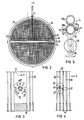
- This lance 1 shows a cleaning device according to the invention, the lance 1 of which is designed according to a first embodiment.
- This lance 1 is inserted through an opening 3 (e.g. a hand hole) of a heat exchanger into a pipe lane or into a pipe gap which is formed by heat exchanger pipes 30.
- the relatively wide pipe alley 21 extends in the X direction; relatively narrow pipe gaps run parallel to it.
- the heat exchanger tubes 30 are perpendicular to the paper plane, that is to say in the Z direction and parallel thereto.
- the illustration shows a lance 1 which is introduced centrally in the Y direction and is made relatively thin and also has a relatively thin nozzle head.
- a total of four cleaning jets 27 are shown parallel to the XZ plane, two on each side of the longitudinal axis of the lance.
- the cleaning device is screwed to the heat exchanger with a flange 5.
- the bottom of this is again designated 15.
- the lance 1 is formed here with the aid of a single tube which is mounted in a hollow cylinder 6, which in turn is connected to the flange 5.
- the lance 1 can also comprise more than one tube.
- a nozzle head 13 is arranged at the end of the lance 1 pointing into the pipe alley. This is provided on the flat radiation side shown with four nozzles 2 aligned with the heat exchanger base 15. These four nozzles 2 are arranged in two rows. Accordingly, a further, oblique to the first radiation side second side can be provided, on which nozzles are also arranged.
- connection head 14 At the opposite end of the lance 1 there is a pivotably arranged connection head 14, via which the detergent supply takes place.
- the connection head 14 is guided on a guide and feed device 12 by means of a holder 16.
- the lance 1 is gradually advanced by means of a spindle 17.
- the spindle 17 is driven by a feed motor 19.
- the lance 1 can gradually step as far into the Heat exchangers are inserted until the holder 16 comes to a stop on a limit switch 18 which is adjustably mounted on a guide rail 20.
- This limit switch 18 ends the automatic motor feed.
- the maximum insertion depth of the lance 1 is determined by the setting or positioning of the limit switch 18 on the guide rail 20.
- an automatic swivel device 4 is arranged below the guide and feed device 12 on the other side of the hollow cylinder 6. It essentially consists of the following units: a motor 7, a pendulum gear 8 connected to its drive axle and a driver 10 guided in the longitudinal grooves 9 of the lance 1 by impellers 11.
- the lance 1 is movably guided in the driver 10 in the longitudinal direction.
- the impellers 11 engaging in the longitudinal grooves 9 of the lance 1
- the lance 1 is pivoted about its longitudinal axis. In this way, the cleaning jets 27 of the nozzle head 13 are pivoted back and forth over the heat exchanger base 15 while the lance 1 is being moved step by step into the pipe lane in question.
- nozzle head 13 there should be noted that more or fewer than four nozzles 2 can be arranged on each radiation side of the nozzle head 13.
- FIG. 3 shows a cross section of a nozzle head 13 inserted into a pipe or inspection lane 21 with a total of four nozzles 2.
- the nozzle head 13 is wider than that of FIG 2; it corresponds to that of FIG. 1.
- the two flat radiation sides on which the two nozzles are located form an angle with one another, for example between 45 ° and 80 °.
- the cleaning jets 27 can act on the heat exchanger base 15 with cleaning agent in its entire width measured in the Y direction at a nozzle swivel angle of only ⁇ 45 °, which is marked by a double arrow. Zeroing the nozzle pivot angle is characterized by the solid arrows that mark the cleaning jets 27.
- a lance 1 is used, which consists of two tubes, each with a small nozzle head 13 attached and with e.g. there are two nozzles per nozzle head 13.
- This lance 1 which can also be referred to as a double lance, is introduced into a tube gap 22 which is much narrower than the tube alley 21 of FIG. 3 and extends in the Y direction.
- Each of the two nozzle heads 13 has a nozzle swivel angle of 45 ° in total.
- the nozzle heads 13 are pivoted in opposite directions, which is illustrated by the solid arrows (starting position) and the dashed arrows (reverse position) for the cleaning jets 27.
- nozzle arrangement in the individual nozzle heads 13 Due to the nozzle arrangement in the individual nozzle heads 13, a uniformly intensive treatment of the heat exchanger base 15 is possible over its entire width. This is favored by the jets 27 of the two nozzle heads 13 pivoting in opposite directions.
- the nozzle heads 13 are each smaller in their largest diameter than the pipe gap 22.
- At least one nozzle 2 is arranged on the one nozzle head 13 in such a way that its cleaning jet 27, in one swivel end position, targets approximately the same direction as the cleaning jet 27 at least one nozzle 2 of the other nozzle head 13, specifically when this other nozzle head 13 has reached its end position at the same time.
- the cleaning jets 27 on one side of the lance 1 swivel towards one another until they have reached approximately the same direction, and then they return to their starting position.
- FIG. 5 shows a section through a lance 1 comprising two tubes 23a, 23b and nozzle heads (not shown) attached at the end shown. At each nozzle head, one or more nozzles 2 are again arranged on one or two radiation sides.
- the tubes 23a, 23b each have a toothing 24 on their circumference.
- the two tubes 23a, 23b are connected to one another in the manner of a transmission in a torque-locking connection.
- the lower or first tube 23b additionally has longitudinal grooves 9 in its surface, in which the impellers 11 of the driver 10 are guided.
- the driver 10 is reciprocated at its other end by a pin 25 located on a disc 26, the disc 26 being driven by a motor 7, whereby the lower or first tube 23b is pivoted.
- each tube 23a, 23b and thus each nozzle head 13 is, for example, ⁇ 22.5 °. So you get by with particularly small swivel angles.
Landscapes
- Physics & Mathematics (AREA)
- Engineering & Computer Science (AREA)
- High Energy & Nuclear Physics (AREA)
- Thermal Sciences (AREA)
- Mechanical Engineering (AREA)
- General Engineering & Computer Science (AREA)
- Vehicle Cleaning, Maintenance, Repair, Refitting, And Outriggers (AREA)
- Cleaning In General (AREA)
- Heat-Exchange Devices With Radiators And Conduit Assemblies (AREA)
Applications Claiming Priority (2)
| Application Number | Priority Date | Filing Date | Title |
|---|---|---|---|
| DE8712637U | 1987-09-18 | ||
| DE8712637U DE8712637U1 (de) | 1987-09-18 | 1987-09-18 | Reinigungsgerät für Wärmetauscher mit Rohrbündeln, insbesondere für den Rohrboden- und Abstandshalterplattenbreich |
Publications (2)
| Publication Number | Publication Date |
|---|---|
| EP0307961A1 true EP0307961A1 (fr) | 1989-03-22 |
| EP0307961B1 EP0307961B1 (fr) | 1990-12-27 |
Family
ID=6812216
Family Applications (1)
| Application Number | Title | Priority Date | Filing Date |
|---|---|---|---|
| EP88115337A Expired - Lifetime EP0307961B1 (fr) | 1987-09-18 | 1988-09-19 | Appareil de nettoyage pour échangeurs de chaleur à faisceaux de tubes, en particulier pour la zone de la plaque tubulaire et de la plaque d'espacement |
Country Status (4)
| Country | Link |
|---|---|
| US (1) | US4844021A (fr) |
| EP (1) | EP0307961B1 (fr) |
| DE (2) | DE8712637U1 (fr) |
| YU (1) | YU107688A (fr) |
Cited By (4)
| Publication number | Priority date | Publication date | Assignee | Title |
|---|---|---|---|---|
| EP0780627A1 (fr) * | 1995-12-22 | 1997-06-25 | Framatome | Procédé et dispositif de nettoyage d'une plaque tubulaire d'un échangeur de chaleur depuis l'intérieur du faisceau de l'échangeur de chaleur |
| GB2468650A (en) * | 2009-03-16 | 2010-09-22 | Tube Tech Int Ltd | Lance for cleaning the shell side of a heat exchanger core |
| GB2468651A (en) * | 2009-03-16 | 2010-09-22 | Tube Tech Int Ltd | Lance for cleaning the shell side of a heat exchanger core |
| WO2010106491A1 (fr) | 2009-03-16 | 2010-09-23 | Tube Tech International Limited | Lance pour nettoyer le côté coque d'un faisceau d'échangeur de chaleur |
Families Citing this family (21)
| Publication number | Priority date | Publication date | Assignee | Title |
|---|---|---|---|---|
| US5069172A (en) * | 1990-09-26 | 1991-12-03 | Westinghouse Electric Corp. | Nuclear steam generator sludge lance method and apparatus |
| US5305713A (en) * | 1992-07-29 | 1994-04-26 | Vadakin, Inc. | Angular rotation rotary cleaning device |
| US5323797A (en) * | 1992-08-07 | 1994-06-28 | Rankin George J | Rotating hose apparatus |
| NL9202174A (nl) * | 1992-12-16 | 1994-07-18 | Peinemann Equipment Bv | Lansmachine met buigzame lans. |
| US5353996A (en) * | 1993-02-18 | 1994-10-11 | Boise Cascade Corporation | Sootblower frame and drive assembly |
| US6672257B1 (en) * | 1994-05-06 | 2004-01-06 | Foster-Miller, Inc. | Upper bundle steam generator cleaning system and method |
| US5564371A (en) * | 1994-05-06 | 1996-10-15 | Foster Miller, Inc. | Upper bundle steam generator cleaning system and method |
| US5615734A (en) * | 1994-11-16 | 1997-04-01 | Westinghouse Electric Corporation | Sludge lance inspection and verification system |
| CA2182509C (fr) * | 1994-12-07 | 2001-01-30 | Foster-Miller, Inc. | Systeme de mise en oeuvre pour dispositif de nettoyage/controle du faisceau tubulaire superieur d'un generateur de vapeur |
| DE29605023U1 (de) * | 1996-01-16 | 1996-09-05 | Köhler, Haiko, 04430 Böhlitz-Ehrenberg | Sicherheitsschlauchführung für Hoch- und Höchstdruckwasserstrahltechnik |
| US20040007254A1 (en) * | 2002-07-12 | 2004-01-15 | Laust Pedersen | Cleaning tool |
| US8176883B2 (en) * | 2009-02-26 | 2012-05-15 | Diamond Power International, Inc. | Retractable articulating robotic sootblower |
| EP2496905B1 (fr) * | 2009-11-03 | 2021-01-06 | Westinghouse Electric Company LLC | Dispositif de lance miniature pour l'élimination de boues |
| WO2011126579A1 (fr) * | 2010-04-10 | 2011-10-13 | Dixon Christopher J | Technique d'entretien d'échangeur de chaleur |
| US20150027499A1 (en) * | 2013-07-24 | 2015-01-29 | Babcock & Wilcox Nuclear Energy, Inc. | Multi-angle sludge lance |
| CA2955049C (fr) | 2014-07-24 | 2022-04-19 | Stoneage, Inc. | Appareil a cadre de positionneur de lance de nettoyage a tube flexible |
| US10024613B2 (en) | 2014-07-24 | 2018-07-17 | Stoneage, Inc. | Flexible tube cleaning lance positioner frame apparatus |
| US9630801B2 (en) | 2014-07-24 | 2017-04-25 | Stoneage, Inc. | Flexible tube cleaning lance drive apparatus |
| CN107175228A (zh) * | 2016-03-10 | 2017-09-19 | 核动力运行研究所 | 蒸汽发生器二次侧第一支撑板下表面水力冲洗导向装置 |
| US10272480B2 (en) | 2016-12-09 | 2019-04-30 | Stoneage, Inc. | Apparatus for remotely propelling a flexible lance into and out of a piping system |
| US11713932B2 (en) | 2020-08-18 | 2023-08-01 | Stoneage, Inc. | Flexible tube cleaning lance positioner frame apparatus |
Citations (3)
| Publication number | Priority date | Publication date | Assignee | Title |
|---|---|---|---|---|
| FR2551182A1 (fr) * | 1983-08-26 | 1985-03-01 | Innus Ind Nuclear Service | Installation pour le nettoyage d'un generateur de vapeur au moyen d'une lance a haute pression |
| BE905193A (nl) * | 1986-07-29 | 1986-11-17 | Smetjet N V | Inrichting voor het met een waterstraal reinigen van een stoomgenerator. |
| US4715324A (en) * | 1985-11-26 | 1987-12-29 | Apex Technologies, Inc. | Nuclear steam generator sludge lancing method and apparatus |
Family Cites Families (9)
| Publication number | Priority date | Publication date | Assignee | Title |
|---|---|---|---|---|
| US3377026A (en) * | 1966-01-24 | 1968-04-09 | Diamond Power Speciality | Retractable cleaning mechanism for boilers and other heat exchangers |
| US4079701A (en) * | 1976-05-17 | 1978-03-21 | Westinghouse Electric Corporation | Steam generator sludge removal system |
| US4273076A (en) * | 1978-12-28 | 1981-06-16 | Westinghouse Electric Corp. | Steam generator sludge lancing apparatus |
| YU40938B (en) * | 1978-12-28 | 1986-08-31 | Westinghouse Electric Corp | Device for vemoving mud sediments from a steam generator |
| US4276856A (en) * | 1978-12-28 | 1981-07-07 | Westinghouse Electric Corp. | Steam generator sludge lancing method |
| FR2514108B1 (fr) * | 1981-10-06 | 1986-06-13 | Framatome Sa | Procede et dispositif d'elimination des boues sur la plaque tubulaire des generateurs de vapeur |
| DE3202248A1 (de) * | 1982-01-25 | 1983-08-04 | Kraftwerk Union AG, 4330 Mülheim | Rohrgassen-manipulator, spritzkopf und zugehoeriges spritzverfahren zum hochdruck-abschlaemmen von waermetauschern |
| US4492187A (en) * | 1983-12-05 | 1985-01-08 | The Babcock & Wilcox Company | Sootblower apparatus |
| US4803959A (en) * | 1988-03-24 | 1989-02-14 | The Babcock & Wilcox Company | Indexing sootblower |
-
1987
- 1987-09-18 DE DE8712637U patent/DE8712637U1/de not_active Expired
-
1988
- 1988-06-02 YU YU01076/88A patent/YU107688A/xx unknown
- 1988-09-16 US US07/245,364 patent/US4844021A/en not_active Expired - Fee Related
- 1988-09-19 DE DE8888115337T patent/DE3861447D1/de not_active Expired - Lifetime
- 1988-09-19 EP EP88115337A patent/EP0307961B1/fr not_active Expired - Lifetime
Patent Citations (3)
| Publication number | Priority date | Publication date | Assignee | Title |
|---|---|---|---|---|
| FR2551182A1 (fr) * | 1983-08-26 | 1985-03-01 | Innus Ind Nuclear Service | Installation pour le nettoyage d'un generateur de vapeur au moyen d'une lance a haute pression |
| US4715324A (en) * | 1985-11-26 | 1987-12-29 | Apex Technologies, Inc. | Nuclear steam generator sludge lancing method and apparatus |
| BE905193A (nl) * | 1986-07-29 | 1986-11-17 | Smetjet N V | Inrichting voor het met een waterstraal reinigen van een stoomgenerator. |
Cited By (8)
| Publication number | Priority date | Publication date | Assignee | Title |
|---|---|---|---|---|
| EP0780627A1 (fr) * | 1995-12-22 | 1997-06-25 | Framatome | Procédé et dispositif de nettoyage d'une plaque tubulaire d'un échangeur de chaleur depuis l'intérieur du faisceau de l'échangeur de chaleur |
| FR2742858A1 (fr) * | 1995-12-22 | 1997-06-27 | Framatome Sa | Procede et dispositif de nettoyage d'une plaque tubulaire d'un echangeur de chaleur depuis l'interieur du faisceau de l'echangeur de chaleur |
| US5782255A (en) * | 1995-12-22 | 1998-07-21 | Framatome | Method and device for cleaning a tube plate of a heat exchanger from inside the bundle of the heat exchanger |
| GB2468650A (en) * | 2009-03-16 | 2010-09-22 | Tube Tech Int Ltd | Lance for cleaning the shell side of a heat exchanger core |
| GB2468651A (en) * | 2009-03-16 | 2010-09-22 | Tube Tech Int Ltd | Lance for cleaning the shell side of a heat exchanger core |
| WO2010106491A1 (fr) | 2009-03-16 | 2010-09-23 | Tube Tech International Limited | Lance pour nettoyer le côté coque d'un faisceau d'échangeur de chaleur |
| GB2468651B (en) * | 2009-03-16 | 2013-03-13 | Tube Tech Int Ltd | Lance for cleaning the shell side of a heat exchanger core |
| GB2468650B (en) * | 2009-03-16 | 2013-03-13 | Tube Tech Int Ltd | Lance for cleaning the shell side of a heat exchanger core |
Also Published As
| Publication number | Publication date |
|---|---|
| DE3861447D1 (de) | 1991-02-07 |
| US4844021A (en) | 1989-07-04 |
| YU107688A (en) | 1991-02-28 |
| EP0307961B1 (fr) | 1990-12-27 |
| DE8712637U1 (de) | 1989-01-12 |
Similar Documents
| Publication | Publication Date | Title |
|---|---|---|
| EP0307961B1 (fr) | Appareil de nettoyage pour échangeurs de chaleur à faisceaux de tubes, en particulier pour la zone de la plaque tubulaire et de la plaque d'espacement | |
| DE69515507T2 (de) | Vorrichtung und system zum waschen von behältern | |
| EP0162309A2 (fr) | Dispositif de nettoyage d'un faisceau de tubes contaminés par radioactivité | |
| DE3000217C2 (de) | Vorrichtung zum Überführen von abgelängten Drähten aus einem losen Drahtbündel in eine Einfachlage von parallelen Drähten | |
| DE69606156T2 (de) | Verfahren und Vorrichtung zur Reinigung der Endplatte eines Wärmetauschers vom Innern des Wärmetauscherbündels | |
| DE3219629A1 (de) | Verbindungselement zur uebertragung einer drehbewegung | |
| EP0016317A1 (fr) | Attelage réglabe en hanteur pour remorque | |
| EP0931600B1 (fr) | Dispositif pour le décalaminage de produits laminés | |
| DE19617860A1 (de) | Sicherheitsvorrichtung für Hochdruckreinigungsgeräte zur Reinigung von Rohrwärmetauschern | |
| DE3805285A1 (de) | Lanzenvorrichtung | |
| DE3611424C2 (de) | Vorrichtung zur selektierten Zuführung von Reinigungskörpern in Kühlwasser führende Rohre von Wärmetauschern | |
| DD232448A5 (de) | Vorrichtung zum automatischen schweissen von rohren | |
| DE3423619C2 (de) | Vorrichtung zur Reinigung der wärmetauschenden Flächen der Speichermassen von Regenerativ-Wärmetauschern | |
| CH646640A5 (en) | Turning bar device in a printing machine | |
| DE2933720A1 (de) | Fluessigkeitsverteilvorrichtung fuer kuehltuerme | |
| DE3301536A1 (de) | Rohrgassen-manipulator | |
| DE60306362T2 (de) | Düsen für eine reinigungsanlage einer druckmaschine | |
| DE3640790C2 (fr) | ||
| EP0205738A2 (fr) | Dispositif pour transporter et retourner en continu des pièces à travers une enceinte de traitement | |
| EP0381186A2 (fr) | Appareil d'ouverture | |
| DE2818611C2 (de) | Reinigungsanordnung zur mechanischen Abtragung von festen Ablagerungen am Rohrboden eines Dampferzeugers | |
| DE9017813U1 (de) | Selbstfanggitter für Viehställe | |
| EP3290855A1 (fr) | Dispositif et procédé de nettoyage à haute pression de tuyaux d'un échangeur de chaleur | |
| DE312000C (fr) | ||
| DE3336232A1 (de) | Automatische werkzeugwechsel-einrichtung fuer werkzeug-maschinen |
Legal Events
| Date | Code | Title | Description |
|---|---|---|---|
| PUAI | Public reference made under article 153(3) epc to a published international application that has entered the european phase |
Free format text: ORIGINAL CODE: 0009012 |
|
| AK | Designated contracting states |
Kind code of ref document: A1 Designated state(s): BE DE FR SE |
|
| 17P | Request for examination filed |
Effective date: 19890808 |
|
| 17Q | First examination report despatched |
Effective date: 19900322 |
|
| GRAA | (expected) grant |
Free format text: ORIGINAL CODE: 0009210 |
|
| AK | Designated contracting states |
Kind code of ref document: B1 Designated state(s): BE DE FR SE |
|
| REF | Corresponds to: |
Ref document number: 3861447 Country of ref document: DE Date of ref document: 19910207 |
|
| ET | Fr: translation filed | ||
| PLBE | No opposition filed within time limit |
Free format text: ORIGINAL CODE: 0009261 |
|
| STAA | Information on the status of an ep patent application or granted ep patent |
Free format text: STATUS: NO OPPOSITION FILED WITHIN TIME LIMIT |
|
| 26N | No opposition filed | ||
| EAL | Se: european patent in force in sweden |
Ref document number: 88115337.3 |
|
| PGFP | Annual fee paid to national office [announced via postgrant information from national office to epo] |
Ref country code: FR Payment date: 19950919 Year of fee payment: 8 |
|
| PGFP | Annual fee paid to national office [announced via postgrant information from national office to epo] |
Ref country code: DE Payment date: 19951116 Year of fee payment: 8 |
|
| PGFP | Annual fee paid to national office [announced via postgrant information from national office to epo] |
Ref country code: BE Payment date: 19960911 Year of fee payment: 9 |
|
| PGFP | Annual fee paid to national office [announced via postgrant information from national office to epo] |
Ref country code: SE Payment date: 19960912 Year of fee payment: 9 |
|
| PG25 | Lapsed in a contracting state [announced via postgrant information from national office to epo] |
Ref country code: FR Effective date: 19960930 |
|
| PG25 | Lapsed in a contracting state [announced via postgrant information from national office to epo] |
Ref country code: DE Effective date: 19970603 |
|
| REG | Reference to a national code |
Ref country code: FR Ref legal event code: ST |
|
| REG | Reference to a national code |
Ref country code: FR Ref legal event code: ST |
|
| PG25 | Lapsed in a contracting state [announced via postgrant information from national office to epo] |
Ref country code: SE Free format text: LAPSE BECAUSE OF NON-PAYMENT OF DUE FEES Effective date: 19970920 |
|
| PG25 | Lapsed in a contracting state [announced via postgrant information from national office to epo] |
Ref country code: BE Free format text: LAPSE BECAUSE OF NON-PAYMENT OF DUE FEES Effective date: 19970930 |
|
| BERE | Be: lapsed |
Owner name: SIEMENS A.G. Effective date: 19970930 |
|
| EUG | Se: european patent has lapsed |
Ref document number: 88115337.3 |