EP0307971A2 - Manchon d'accouplement pour raccorder deux extrémités de tuyaux - Google Patents
Manchon d'accouplement pour raccorder deux extrémités de tuyaux Download PDFInfo
- Publication number
- EP0307971A2 EP0307971A2 EP88117883A EP88117883A EP0307971A2 EP 0307971 A2 EP0307971 A2 EP 0307971A2 EP 88117883 A EP88117883 A EP 88117883A EP 88117883 A EP88117883 A EP 88117883A EP 0307971 A2 EP0307971 A2 EP 0307971A2
- Authority
- EP
- European Patent Office
- Prior art keywords
- sleeve
- securing
- fingers
- sealing body
- coupling
- Prior art date
- Legal status (The legal status is an assumption and is not a legal conclusion. Google has not performed a legal analysis and makes no representation as to the accuracy of the status listed.)
- Granted
Links
Images
Classifications
-
- F—MECHANICAL ENGINEERING; LIGHTING; HEATING; WEAPONS; BLASTING
- F16—ENGINEERING ELEMENTS AND UNITS; GENERAL MEASURES FOR PRODUCING AND MAINTAINING EFFECTIVE FUNCTIONING OF MACHINES OR INSTALLATIONS; THERMAL INSULATION IN GENERAL
- F16L—PIPES; JOINTS OR FITTINGS FOR PIPES; SUPPORTS FOR PIPES, CABLES OR PROTECTIVE TUBING; MEANS FOR THERMAL INSULATION IN GENERAL
- F16L37/00—Couplings of the quick-acting type
- F16L37/08—Couplings of the quick-acting type in which the connection between abutting or axially overlapping ends is maintained by locking members
- F16L37/12—Couplings of the quick-acting type in which the connection between abutting or axially overlapping ends is maintained by locking members using hooks, pawls, or other movable or insertable locking members
- F16L37/138—Couplings of the quick-acting type in which the connection between abutting or axially overlapping ends is maintained by locking members using hooks, pawls, or other movable or insertable locking members using an axially movable sleeve
-
- F—MECHANICAL ENGINEERING; LIGHTING; HEATING; WEAPONS; BLASTING
- F02—COMBUSTION ENGINES; HOT-GAS OR COMBUSTION-PRODUCT ENGINE PLANTS
- F02M—SUPPLYING COMBUSTION ENGINES IN GENERAL WITH COMBUSTIBLE MIXTURES OR CONSTITUENTS THEREOF
- F02M55/00—Fuel-injection apparatus characterised by their fuel conduits or their venting means; Arrangements of conduits between fuel tank and pump F02M37/00
- F02M55/004—Joints; Sealings
-
- F—MECHANICAL ENGINEERING; LIGHTING; HEATING; WEAPONS; BLASTING
- F16—ENGINEERING ELEMENTS AND UNITS; GENERAL MEASURES FOR PRODUCING AND MAINTAINING EFFECTIVE FUNCTIONING OF MACHINES OR INSTALLATIONS; THERMAL INSULATION IN GENERAL
- F16L—PIPES; JOINTS OR FITTINGS FOR PIPES; SUPPORTS FOR PIPES, CABLES OR PROTECTIVE TUBING; MEANS FOR THERMAL INSULATION IN GENERAL
- F16L33/00—Arrangements for connecting hoses to rigid members; Rigid hose-connectors, i.e. single members engaging both hoses
- F16L33/30—Arrangements for connecting hoses to rigid members; Rigid hose-connectors, i.e. single members engaging both hoses comprising parts inside the hoses only
-
- F—MECHANICAL ENGINEERING; LIGHTING; HEATING; WEAPONS; BLASTING
- F16—ENGINEERING ELEMENTS AND UNITS; GENERAL MEASURES FOR PRODUCING AND MAINTAINING EFFECTIVE FUNCTIONING OF MACHINES OR INSTALLATIONS; THERMAL INSULATION IN GENERAL
- F16L—PIPES; JOINTS OR FITTINGS FOR PIPES; SUPPORTS FOR PIPES, CABLES OR PROTECTIVE TUBING; MEANS FOR THERMAL INSULATION IN GENERAL
- F16L37/00—Couplings of the quick-acting type
- F16L37/08—Couplings of the quick-acting type in which the connection between abutting or axially overlapping ends is maintained by locking members
- F16L37/12—Couplings of the quick-acting type in which the connection between abutting or axially overlapping ends is maintained by locking members using hooks, pawls, or other movable or insertable locking members
- F16L37/133—Couplings of the quick-acting type in which the connection between abutting or axially overlapping ends is maintained by locking members using hooks, pawls, or other movable or insertable locking members using flexible hooks
-
- F—MECHANICAL ENGINEERING; LIGHTING; HEATING; WEAPONS; BLASTING
- F02—COMBUSTION ENGINES; HOT-GAS OR COMBUSTION-PRODUCT ENGINE PLANTS
- F02M—SUPPLYING COMBUSTION ENGINES IN GENERAL WITH COMBUSTIBLE MIXTURES OR CONSTITUENTS THEREOF
- F02M2200/00—Details of fuel-injection apparatus, not otherwise provided for
- F02M2200/85—Mounting of fuel injection apparatus
- F02M2200/853—Mounting of fuel injection apparatus involving use of quick-acting mechanism, e.g. clips
Definitions
- the invention relates to a coupling sleeve for connecting the ends of two lines for flowing media, in particular for fuel lines on internal combustion engines, with a sleeve part which has at least one insertion opening for receiving a line end.
- the invention is based on the object of creating a socket connection of the type described at the outset which fulfills the requirements listed above.
- At least two locking fingers which can be deflected transversely to the insertion opening are arranged on the sleeve part in the region of the insertion opening, the free ends of which are each provided with radially inwardly directed projections which act on the outer wall of a tubular elastic sealing body forming the insertion opening and in that an axially displaceable securing sleeve which can be snapped onto the sleeve part is provided, which in its operating position essentially engages around the free ends of the securing fingers.
- a coupling sleeve designed in this way has a number of advantages.
- the free end of the pipe to be connected either a pipe or a hose, with a pipe insert in the end area can be inserted into the insertion opening of the socket part in a simple plug-in installation, the tubular sealing body made of elastic material in the socket part having the cable end pushed in on it Seals around the outer surface.
- the free opening of the elastic sealing body has a somewhat smaller diameter from the outer diameter of the line end to be inserted, so that when the line end is inserted, the sealing body is correspondingly pressed and the required Sealing force is present.
- tubular sealing body in contrast to the hitherto known couplings, has a sufficient deformation volume, additional deformations of the elastic sealing body will not impair the sealing force when the coupling sleeve is loaded by transverse forces.
- the inserted line end is sealed over a considerable length on its outer surface by the sealing body, wherein in the area of the lugs of the securing fingers, a pressure force between the sealing body and the line end becomes effective due to the pushed-over securing sleeve, which improves the sealing effect.
- the annular projection arranged at the end of the line now lies within the sealing body, there is nevertheless a positive-locking securing of the end of the line against being pulled out by the projections of the securing fingers.
- protrusions are provided on the securing fingers in the area of the lugs on the sealing body on the outside, which form a detent defining the operating position in cooperation with the securing sleeve, then, with a corresponding shaping of the protrusions, both securing the operating position and the desired increase can be achieved achieve the sealing effect, which is not reduced by transverse forces acting on the line.
- a preferred embodiment of the invention provides that the securing fingers have a fixed end are attached to a retaining ring which engages around the socket part in a form-fitting manner.
- the arrangement of the locking fingers as a separate component requires an additional operation when assembling the clutch sleeve, since the retaining ring and the sleeve part initially must be put together and then the locking sleeve must be pushed over.
- the particular advantage of this design is that it makes it possible to directly vulcanize the elastic sealing body into a cup-like extension in the sleeve part that is open against the direction of insertion, since the edge of the insertion opening is exposed, so that the sleeve part and the tool are moved in rotation relative to one another can and the elastic material can be introduced.
- the particular advantage here lies in the fact that the vulcanization of the elastic sealing body, the connection between the sealing body and the socket part is absolutely tight, so that only by appropriate compression between the sealing body and inserted pipe part for the seal between the socket part and the end of the line is to be taken care of.
- the retaining ring carrying the securing fingers is divided.
- the retaining ring can either consist of two loose sections or can be provided in one piece with a thin flexible connection, as is possible when producing from a plastic in the form of a so-called "film hinge".
- the retaining ring is expediently cup-shaped and engages around a correspondingly shaped retaining web on the sleeve part, so that the retaining ring is positively and axially displaceably connected to the sleeve part with the locking fingers.
- the securing fingers are colored differently than the securing sleeve, at least in the area of their free ends. This has the advantage that in the assembly position described above, the assembly position is visible through the color of the securing fingers, so that an optical check is also possible as to whether the securing sleeve is also shifted into the operating position after assembly. With appropriate length training of the Si securing sleeve completely covers the securing fingers in the operating position.
- At least the securing sleeve is made of metal and is guided on the sleeve part at a radial distance and, in the operating position, covers the sleeve part including the securing fingers and part of the flexible hose line connected to the sleeve part. This allows the fire resistance to be increased even in the case of plug-in socket parts made of plastic, as is desirable, for example, for fuel lines.
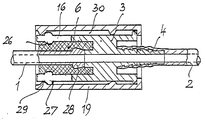
- the embodiment shown has an elastic sealing body 6 which is fixedly connected to a socket part 3, is of tubular design and sealingly encloses the inserted end of the pipeline 1 on the outside over a greater length.
- the sleeve part 3 forms, together with securing fingers 16, a cylindrical receiving space for the tubular sealing body 6, the securing fingers 16 lying loosely on the outside of the sealing body 6 in the installed position.
- the sleeve part 3 is surrounded by an axially displaceable securing sleeve 19.
- the securing fingers 16 are provided in the region of their free ends with projections 26 on the inside as well as with projections 27 on the outside.
- the pipeline 1 provided at its end with a bead 28 can be pressed into the sealing body 6, since the securing fingers 16 bend outwards accordingly due to their elasticity.
- the securing sleeve 19 is advanced into the operating position shown, namely until one is on the inside Licher annular projection 29 which also engages around a ring forming projections 27 of the locking fingers 16.
- the securing sleeve 19 is made of metal, in the case of parts which are otherwise made of plastic, then there is an additional increase in the fire resistance of the coupling sleeve, since a heat-conducting connection between these parts is limited to a few narrow zones and the intermediate space 30 has an insulating effect.
- An increase in fire resistance to, for example, three minutes can be life-saving in the event of an accident when used in motor vehicle construction.
- the securing fingers 16 are integrally formed on the sleeve part 3.
Landscapes
- Engineering & Computer Science (AREA)
- General Engineering & Computer Science (AREA)
- Mechanical Engineering (AREA)
- Chemical & Material Sciences (AREA)
- Combustion & Propulsion (AREA)
- Quick-Acting Or Multi-Walled Pipe Joints (AREA)
- Shaping Of Tube Ends By Bending Or Straightening (AREA)
Applications Claiming Priority (2)
| Application Number | Priority Date | Filing Date | Title |
|---|---|---|---|
| DE3438173 | 1984-10-18 | ||
| DE19843438173 DE3438173A1 (de) | 1984-10-18 | 1984-10-18 | Kupplungsmuffe zum verbinden von zwei rohrleitungsenden |
Related Parent Applications (1)
| Application Number | Title | Priority Date | Filing Date |
|---|---|---|---|
| EP85113037.7 Division | 1985-10-15 |
Publications (3)
| Publication Number | Publication Date |
|---|---|
| EP0307971A2 true EP0307971A2 (fr) | 1989-03-22 |
| EP0307971A3 EP0307971A3 (en) | 1989-04-05 |
| EP0307971B1 EP0307971B1 (fr) | 1991-12-18 |
Family
ID=6248186
Family Applications (2)
| Application Number | Title | Priority Date | Filing Date |
|---|---|---|---|
| EP85113037A Expired - Lifetime EP0178626B1 (fr) | 1984-10-18 | 1985-10-15 | Manchon d'accouplement pour raccorder deux extrémités de tuyaux |
| EP88117883A Expired - Lifetime EP0307971B1 (fr) | 1984-10-18 | 1985-10-15 | Manchon d'accouplement pour raccorder deux extrémités de tuyaux |
Family Applications Before (1)
| Application Number | Title | Priority Date | Filing Date |
|---|---|---|---|
| EP85113037A Expired - Lifetime EP0178626B1 (fr) | 1984-10-18 | 1985-10-15 | Manchon d'accouplement pour raccorder deux extrémités de tuyaux |
Country Status (2)
| Country | Link |
|---|---|
| EP (2) | EP0178626B1 (fr) |
| DE (3) | DE3438173A1 (fr) |
Cited By (4)
| Publication number | Priority date | Publication date | Assignee | Title |
|---|---|---|---|---|
| DE3819932A1 (de) * | 1987-06-19 | 1988-12-29 | Weber Srl | Verbindungseinheit in einer brennstoffleitung |
| DE4006200A1 (de) * | 1990-02-28 | 1991-08-29 | Continental Ag | Automatisch montierbare steckkupplung fuer leitungsschlaeuche in kraftfahrzeugen |
| DE29721023U1 (de) * | 1997-11-27 | 1998-01-22 | Armaturenfabrik Hermann Voss GmbH + Co, 51688 Wipperfürth | Rastbarer Leitungsverbinder insbesondere für Kraftstoffleitungen |
| WO2005059426A1 (fr) * | 2003-12-17 | 2005-06-30 | Voss Automotive Gmbh | Raccord de conduite emboitable et blocable |
Families Citing this family (4)
| Publication number | Priority date | Publication date | Assignee | Title |
|---|---|---|---|---|
| DE3741250A1 (de) * | 1987-12-05 | 1989-06-15 | Voss Armaturen | Vorrichtung zum gegenseitigen verbinden von zwei leitungen, insbesondere kraftstoffleitungen |
| DE4240136C1 (fr) * | 1992-01-10 | 1993-06-17 | Rasmussen Gmbh, 6457 Maintal, De | |
| DE102013200620A1 (de) * | 2012-02-09 | 2013-08-14 | Schaeffler Technologies AG & Co. KG | Verbindung für eine Niederdruckleitung |
| CN115059696B (zh) * | 2022-05-12 | 2023-11-10 | 无锡瑞金源机械有限公司 | 一种便于与轴连接的联轴器轴套 |
Family Cites Families (14)
| Publication number | Priority date | Publication date | Assignee | Title |
|---|---|---|---|---|
| US3674292A (en) * | 1969-10-15 | 1972-07-04 | Amp Inc | Tubular connection devices |
| DE2307154A1 (de) * | 1973-02-14 | 1974-08-22 | Daimler Benz Ag | Schlauch- oder rohrverbindungselement |
| US3916929A (en) * | 1974-08-16 | 1975-11-04 | Scovill Manufacturing Co | Self-sealing break-away fitting |
| DE2622269C3 (de) * | 1976-05-19 | 1979-05-23 | Technoform Caprano + Brunnhofer Kg, 3501 Fuldabrueck | Anschlußeinrichtung zwischen einem Kunststoffrohr und einem stationären Anschlußstutzen |
| FR2359358A1 (fr) * | 1976-07-23 | 1978-02-17 | Ferodo Sa | Dispositif de connecteur |
| IT1086546B (it) * | 1977-05-23 | 1985-05-28 | Uniflex Spa | Giunto per tubi flessibili ad aggancio e sgancio rapido |
| FR2425605A1 (fr) * | 1978-05-11 | 1979-12-07 | Staubli Sa Ets | Perfectionnements aux colliers de raccordement pour tuyaux souples |
| DE2830799C2 (de) * | 1978-07-13 | 1983-11-17 | Technoform Caprano + Brunnhofer KG, 3501 Fuldabrück | Anschlußeinrichtung für eine Kraftfahrzeug-Rohrleitung |
| US4296950A (en) * | 1979-07-18 | 1981-10-27 | Dresser Industries, Inc. | Corrosion resistant pipe joint |
| US4601497A (en) * | 1980-10-29 | 1986-07-22 | Proprietary Technology | Swivelable quick connector assembly |
| US4332402A (en) * | 1980-10-30 | 1982-06-01 | General Motors Corporation | Quick connect hydraulic coupling assembly |
| IT1214330B (it) * | 1982-02-26 | 1990-01-10 | Uniflex Utiltime Spa | Raccordo per connessione di tubi flessibili di diametro notevolmente vario. |
| FR2528148B1 (fr) * | 1982-06-08 | 1986-04-18 | Ind | Dispositif d'accouplement autoverrouillable |
| US4451069A (en) * | 1982-08-09 | 1984-05-29 | Smith Investment Company | Quick connect fluid coupling |
-
1984
- 1984-10-18 DE DE19843438173 patent/DE3438173A1/de not_active Withdrawn
-
1985
- 1985-10-15 DE DE8888117883T patent/DE3584979D1/de not_active Expired - Fee Related
- 1985-10-15 EP EP85113037A patent/EP0178626B1/fr not_active Expired - Lifetime
- 1985-10-15 EP EP88117883A patent/EP0307971B1/fr not_active Expired - Lifetime
- 1985-10-15 DE DE8585113037T patent/DE3577906D1/de not_active Expired - Fee Related
Cited By (6)
| Publication number | Priority date | Publication date | Assignee | Title |
|---|---|---|---|---|
| DE3819932A1 (de) * | 1987-06-19 | 1988-12-29 | Weber Srl | Verbindungseinheit in einer brennstoffleitung |
| DE3819932C2 (de) * | 1987-06-19 | 1998-02-05 | Magneti Marelli Spa | Verbindungseinheit in einer Brennstoffleitung |
| DE4006200A1 (de) * | 1990-02-28 | 1991-08-29 | Continental Ag | Automatisch montierbare steckkupplung fuer leitungsschlaeuche in kraftfahrzeugen |
| DE29721023U1 (de) * | 1997-11-27 | 1998-01-22 | Armaturenfabrik Hermann Voss GmbH + Co, 51688 Wipperfürth | Rastbarer Leitungsverbinder insbesondere für Kraftstoffleitungen |
| WO2005059426A1 (fr) * | 2003-12-17 | 2005-06-30 | Voss Automotive Gmbh | Raccord de conduite emboitable et blocable |
| EP2050996A1 (fr) * | 2003-12-17 | 2009-04-22 | Voss Automotive GmbH | Liaison câblée enfichable et pouvant être bloquée |
Also Published As
| Publication number | Publication date |
|---|---|
| EP0307971B1 (fr) | 1991-12-18 |
| EP0307971A3 (en) | 1989-04-05 |
| EP0178626B1 (fr) | 1990-05-23 |
| DE3438173A1 (de) | 1986-04-24 |
| EP0178626A1 (fr) | 1986-04-23 |
| DE3577906D1 (de) | 1990-06-28 |
| DE3584979D1 (de) | 1992-01-30 |
Similar Documents
| Publication | Publication Date | Title |
|---|---|---|
| DE69320545T2 (de) | Schlauchverbindung | |
| EP2054648B1 (fr) | Manchon d'étanchéité ou soufflet | |
| DE69004490T2 (de) | Vorrichtung zum dichten Verbinden eines Rohres mit einem Schlauch. | |
| DE4022558A1 (de) | Dichtungsvorrichtungen fuer durchflussoeffnungen | |
| DE102015207231A1 (de) | Filtereinrichtung | |
| DE10147131A1 (de) | Gleitanordnung für eine Lenksäule | |
| DE2952468A1 (de) | Steckbare verbindungsvorrichtung mit schnappverschluss | |
| WO2009007165A1 (fr) | Tuyau d'air de charge | |
| DE69611063T2 (de) | Dichte Verbindung mit radialem Einsteckende | |
| DE60205641T2 (de) | Zur verbindung zweier röhrenförmiger elemente verwendete kupplung und montageverfahren dafür | |
| EP0307971B1 (fr) | Manchon d'accouplement pour raccorder deux extrémités de tuyaux | |
| EP1673185B1 (fr) | Procede et dispositif pour etablir une liaison serree entre tubes au niveau d'un raccord | |
| DE102011121828A1 (de) | Steckverbindungsanordnung für Fluidleitungen | |
| EP1980759B1 (fr) | Système de raccordement modulaire pour câbles de commande ainsi que procédé et dispositif d'assemblage destinés à sa fabrication | |
| DE19608870C1 (de) | Steckverbindung für Abgasleitungen | |
| DE102017106200A1 (de) | Kunststoff-Abgasmuffenrohr sowie Heizungssystem | |
| WO2000020772A1 (fr) | Ensemble annele premonte destine a envelopper des arbres articules | |
| DE102018125349B4 (de) | Verbindungsanordnung zur Drehmomentübertragung, Verfahren zur Herstellung einer solchen Verbindungsanordnung sowie Verwendung einer solchen Verbindungsanordnung | |
| DE102011102018A1 (de) | Klappeneinrichtung | |
| DE9306742U1 (de) | Thermostatventil | |
| DE20103393U1 (de) | Rasteinrichtung für Getriebeteile | |
| DE9114365U1 (de) | Kupplungsmuffe für Kraftstoffleitungen | |
| DE102009030372A1 (de) | Am Kreuzgelenkzapfen befestigte Lagerbüchsendichtung | |
| DE102015203390A1 (de) | Verfahren zur Herstellung eines Filterkopfes | |
| DE102018218632A1 (de) | Filtereinrichtung |
Legal Events
| Date | Code | Title | Description |
|---|---|---|---|
| PUAI | Public reference made under article 153(3) epc to a published international application that has entered the european phase |
Free format text: ORIGINAL CODE: 0009012 |
|
| PUAL | Search report despatched |
Free format text: ORIGINAL CODE: 0009013 |
|
| AC | Divisional application: reference to earlier application |
Ref document number: 178626 Country of ref document: EP |
|
| AK | Designated contracting states |
Kind code of ref document: A2 Designated state(s): DE FR GB IT |
|
| AK | Designated contracting states |
Kind code of ref document: A3 Designated state(s): DE FR GB IT |
|
| 17P | Request for examination filed |
Effective date: 19890907 |
|
| 17Q | First examination report despatched |
Effective date: 19900207 |
|
| GRAA | (expected) grant |
Free format text: ORIGINAL CODE: 0009210 |
|
| AC | Divisional application: reference to earlier application |
Ref document number: 178626 Country of ref document: EP |
|
| AK | Designated contracting states |
Kind code of ref document: B1 Designated state(s): DE FR GB IT |
|
| PG25 | Lapsed in a contracting state [announced via postgrant information from national office to epo] |
Ref country code: IT Free format text: LAPSE BECAUSE OF FAILURE TO SUBMIT A TRANSLATION OF THE DESCRIPTION OR TO PAY THE FEE WITHIN THE PRE;WARNING: LAPSES OF ITALIAN PATENTS WITH EFFECTIVE DATE BEFORE 2007 MAY HAVE OCCURRED AT ANY TIME BEFORE 2007. THE CORRECT EFFECTIVE DATE MAY BE DIFFERENT FROM THE ONE RECORDED.SCRIBED TIME-LIMIT Effective date: 19911218 |
|
| REF | Corresponds to: |
Ref document number: 3584979 Country of ref document: DE Date of ref document: 19920130 |
|
| ET | Fr: translation filed | ||
| GBT | Gb: translation of ep patent filed (gb section 77(6)(a)/1977) | ||
| PLBE | No opposition filed within time limit |
Free format text: ORIGINAL CODE: 0009261 |
|
| STAA | Information on the status of an ep patent application or granted ep patent |
Free format text: STATUS: NO OPPOSITION FILED WITHIN TIME LIMIT |
|
| 26N | No opposition filed | ||
| PGFP | Annual fee paid to national office [announced via postgrant information from national office to epo] |
Ref country code: GB Payment date: 19931028 Year of fee payment: 9 |
|
| PGFP | Annual fee paid to national office [announced via postgrant information from national office to epo] |
Ref country code: FR Payment date: 19931029 Year of fee payment: 9 |
|
| PGFP | Annual fee paid to national office [announced via postgrant information from national office to epo] |
Ref country code: DE Payment date: 19931108 Year of fee payment: 9 |
|
| PG25 | Lapsed in a contracting state [announced via postgrant information from national office to epo] |
Ref country code: GB Effective date: 19941015 |
|
| GBPC | Gb: european patent ceased through non-payment of renewal fee |
Effective date: 19941015 |
|
| PG25 | Lapsed in a contracting state [announced via postgrant information from national office to epo] |
Ref country code: FR Effective date: 19950630 |
|
| PG25 | Lapsed in a contracting state [announced via postgrant information from national office to epo] |
Ref country code: DE Effective date: 19950701 |
|
| REG | Reference to a national code |
Ref country code: FR Ref legal event code: ST |