EP0308016B1 - Schieberventil für Flüssigkeits- oder Gasleitungen - Google Patents
Schieberventil für Flüssigkeits- oder Gasleitungen Download PDFInfo
- Publication number
- EP0308016B1 EP0308016B1 EP88201962A EP88201962A EP0308016B1 EP 0308016 B1 EP0308016 B1 EP 0308016B1 EP 88201962 A EP88201962 A EP 88201962A EP 88201962 A EP88201962 A EP 88201962A EP 0308016 B1 EP0308016 B1 EP 0308016B1
- Authority
- EP
- European Patent Office
- Prior art keywords
- passage chamber
- opening
- liquid
- valve
- valve body
- Prior art date
- Legal status (The legal status is an assumption and is not a legal conclusion. Google has not performed a legal analysis and makes no representation as to the accuracy of the status listed.)
- Expired - Lifetime
Links
Images

Classifications
-
- F—MECHANICAL ENGINEERING; LIGHTING; HEATING; WEAPONS; BLASTING
- F16—ENGINEERING ELEMENTS AND UNITS; GENERAL MEASURES FOR PRODUCING AND MAINTAINING EFFECTIVE FUNCTIONING OF MACHINES OR INSTALLATIONS; THERMAL INSULATION IN GENERAL
- F16K—VALVES; TAPS; COCKS; ACTUATING-FLOATS; DEVICES FOR VENTING OR AERATING
- F16K3/00—Gate valves or sliding valves, i.e. cut-off apparatus with closing members having a sliding movement along the seat for opening and closing
- F16K3/02—Gate valves or sliding valves, i.e. cut-off apparatus with closing members having a sliding movement along the seat for opening and closing with flat sealing faces; Packings therefor
- F16K3/0209—Gate valves or sliding valves, i.e. cut-off apparatus with closing members having a sliding movement along the seat for opening and closing with flat sealing faces; Packings therefor the valve having a particular passage, e.g. provided with a filter, throttle or safety device
-
- F—MECHANICAL ENGINEERING; LIGHTING; HEATING; WEAPONS; BLASTING
- F16—ENGINEERING ELEMENTS AND UNITS; GENERAL MEASURES FOR PRODUCING AND MAINTAINING EFFECTIVE FUNCTIONING OF MACHINES OR INSTALLATIONS; THERMAL INSULATION IN GENERAL
- F16K—VALVES; TAPS; COCKS; ACTUATING-FLOATS; DEVICES FOR VENTING OR AERATING
- F16K3/00—Gate valves or sliding valves, i.e. cut-off apparatus with closing members having a sliding movement along the seat for opening and closing
- F16K3/02—Gate valves or sliding valves, i.e. cut-off apparatus with closing members having a sliding movement along the seat for opening and closing with flat sealing faces; Packings therefor
- F16K3/0227—Packings
Definitions
- the invention relates to a slide valve with or without a pressure regulator for liquid or gas pipes.
- a sliding valve intended to stop liquids, gases or vapors circulating in pipes or to regulate the quantity which passes.
- a slide which is slidable from bottom to top and from top to bottom against one or two valve seats.
- the valve of the invention mainly comprises a body forming part of a closed assembly; a supply channel which opens into said body and is connected to the liquid or gas supply pipe; a passage chamber with two walls located one opposite the other and housed in said closed assembly; an evacuation channel which opens on one side into the passage chamber and which is connected on the other side to the liquid or gas evacuation pipe; in at least one of said walls of the passage chamber, an opening which places the body in communication with the passage chamber, the passage chamber, with the exception of said opening, respectively said openings, being sealed with respect to said assembly; a valve body which is movably housed between said two walls and which cooperates with said opening or said openings allowing the passage between the said body and the passage chamber to be closed, the valve body having a transverse opening; a movable rod to which said valve body is attached; means for moving this rod, at least one hard material stop element between said valve body and said opening wall on the one hand and the other wall on the other hand; and at least one elastic element for pushing the one or
- the valve of the invention mainly comprises a body forming part of a closed assembly; a supply channel which opens into said body and is connected to the liquid supply pipe or gas; a passage chamber with two walls located one opposite the other and housed in said closed assembly; an evacuation channel which opens on one side into the passage chamber and which is connected on the other side to the liquid or gas evacuation pipe; in said walls of the passage chamber at least one pair of oppositely located openings which places the body in communication with the passage chamber, the passage chamber, with the exception of said openings being sealed with respect to said assembly; a valve body which is movably housed between said two walls and which cooperates with said pair of openings allowing the closing of said openings; a movable rod to which said valve body is attached; means for moving this rod, a pair of at least one hard material stop element between said valve body and said opening walls; and a pair of at least one elastic element for pushing the stop elements into contact with the aforementioned valve body in a water and gas tight manner; the sections of the openings
- valve body By the fact that in the closed position of the valve body the pressure of the incoming liquid or gas acts on both sides of the valve body, a balance is created, as a result of which the valve body is movable independently of the pressure. This effect becomes even more noticeable when the valve body is perforated, so that in the closed position thereof the liquid or gas can freely pass through. In addition, in the event of a sudden production of a pressure difference, the valve body will not be subjected to an impact, so that the fracture of this body will be avoided.
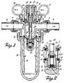
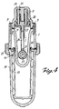
- the body 1 of the valve with the passage chamber 2, which is provided at the bottom of two parallel walls, in which are arranged two openings 3 located one opposite the other.
- the passage chamber 2 has an evacuation channel 4.
- the body 1 has at the top a supply channel 5, so that a liquid or a gas entering through this supply channel into the body is diverted via the openings 3, the passage chamber 2 and the evacuation channel 4 and is evacuated.
- a screw connection 6 is attached by means of a coupling nut 7, to which screw connections are connected respectively a supply line and a line d '' discharge (not shown) from a water or gas pipe.
- the open upper part of the body 1 is closed by means of a hollow head 8 fixed to the body 1 by means of screws 9.
- two manometers, respectively 10 and 11, which via a perforation, respectively 12- 13, are in communication with the supply channel 5 and the discharge channel 4 respectively, so that the pressure of the liquid or gas entering and leaving can be controlled.
- the lower part of the body 1 is closed by means of a bell 14, which is fixed to the body 1 by means of a coupling nut 15.
- the body has a narrowed part, the two parallel flat walls of which with the openings 3 provided therein are part.
- each opening 3 of the body 1 is also arranged with play a circular closing element 20 preferably made of hard ceramic, which by means of a circular elastic element 21 bears against the inside of the profiled edge of the adjacent opening 17 of the frame 16 that the element in question is axially displaceable and that a good seal is obtained.
- a circular closing element 20 preferably made of hard ceramic, which by means of a circular elastic element 21 bears against the inside of the profiled edge of the adjacent opening 17 of the frame 16 that the element in question is axially displaceable and that a good seal is obtained.
- each annular stop element 20 operates an annular element stop 22, preferably hard ceramic, and which is part of the valve body 35 itself.
- annular stop elements are housed in an opening 23 in the head of a rod 24 movable in height.
- Each annular stop element is pushed against its respective annular stop element 20 by an elastic annular element 25, which is placed between this annular stop element and an intermediate ring 26 placed in said head of the rod 24 movable in height .
- the elastic annular elements 21 and 25 the annular stop elements 20 and 22 are strongly pushed one against the other, regardless of the position of the stop elements 22 relative to the stop elements 20. A perfect closure is therefore possible thanks to this.
- the rod 24 displaceable in height is fixed in a clamping member 27, which in turn is fixed on a hollow cylinder head 28. Between this hollow cylinder head and the head 8 are placed two pressure springs, respectively 29-30, whose pressure power is chosen so that the valve can only close when the incoming liquid or gas reaches a determined pressure. This part of the valve therefore serves as a pressure regulator.
- a membrane 31 which completely separates the space in the hollow head 8 from that of the body 1.
- the space in said head is in communication with the atmosphere by a bore 32 provided in the head.
- a guide pin 33 forming part of the head freely slides a guide box 34 forming part of the cylinder head 28, so that the cylinder head is effectively guided during its movement.
Landscapes
- Engineering & Computer Science (AREA)
- General Engineering & Computer Science (AREA)
- Mechanical Engineering (AREA)
- Sliding Valves (AREA)
- Lift Valve (AREA)
- Self-Closing Valves And Venting Or Aerating Valves (AREA)
- Pipeline Systems (AREA)
- Pipe Accessories (AREA)
Claims (10)
- Schieberventil für Flüssigkeits- oder Gasleitungen, hauptsächlich enthaltend ein Gehäuse (1), das einen Teil einer geschlossenen Einheit darstellt; einen Zufuhrkanal (5), der in besagtes Gehäuse mündet und der an die Flüssigkeits- oder Gaszufuhrleitung angeschlossen ist; eine Durchlaßkammer (2) mit zwei Wänden, die einander gegenüber angeordnet sind und in besagter geschlossener Einheit untergebracht sind; einen Auslaßkanal (4), der an einer Seite in die Durchlaßkammer (2) mündet und der an der anderen Seite an die Flüssigkeits- oder Gasabflußleitung angeschlossen ist; in wenigstens einer der besagten Wände der Durchlaßkammer (2) eine Öffnung (3), die das Gehäuse mit der Durchlaßkammer verbindet, wobei die Durchlaßkammer (2), mit Ausnahme von besagter Öffnung (3) bzw. besagten Öffnungen (3) in Bezug zur besagten Einheit dicht ist; einen Ventilkörper (35), der beweglich zwischen den besagten zwei Wänden angebracht ist und der mit besagter Öffnung oder besagten Öffnungen zusammenwirkt, wobei dieser es gestattet, den Durchlaß zwischen besagtem Gehäuse (1) und der Durchlaßkammer (2) abzuschließen, und wobei der Ventilkörper (35) eine Queröffnung aufweist; eine bewegliche Stange (24), woran der besagte Ventilkörper befestigt ist; ein Mittel (28), um diese Stange zu bewegen, mindestens ein Abschließelement (20-22) aus hartem Material zwischen dem besagten Ventilkörper (35) und der besagten mit der besagten Öffnung (3) versehenen Wand einerseits und der anderen Wand andererseits; und mindestens ein elastisches Element (21-25), um das Abschließelement oder die Abschließelemente (20-22) wasser- und gasdicht in Kontakt mit dem vorgenannten Ventilkörper (35) zu drücken; wobei die Querschnitte der Öffnungen in den Wänden der Durchlaßkammer (2) und in dem Ventilkörper (35) so gewählt sind, daß in geschlossener Position des Ventils die Summe der Seitenkräfte, die auf den Ventilkörper (35) ausgeübt werden, gleich null ist.
- Ventil für Flüssigkeits- oder Gasleitungen, enthaltend in der Hauptsache ein Gehäuse (1), das einen Teil einer geschlossenen Einheit darstellt; einen Zufuhrkanal (5), der in besagtes Gehäuse mündet und der an die Flüssigkeits- oder Gaszufuhrleitung angeschlossen ist; eine Durchlaßkammer (2) mit zwei Wänden, die einander gegenüber angeordnet und in besagter geschlossener Einheit untergebracht sind; einen Auslaßkanal (4), der an einer Seite in die Durchlaßkammer (2) mündet und der an der anderen Seite an die Flüssigkeits- oder Gasabflußleitung angeschlossen ist; in besagten Wänden der Durchlaßkammer (2) mindestens ein Paar einander gegenüberliegender Öffnungen (3), welches das Gehäuse mit der Durchlaßkammer (2) in Verbindung setzt, wobei diese Durchlaßkammer (2), mit Ausnahme besagter Öffnungen (3), in Bezug zur besagten Einheit dicht ist; einen Ventilkörper (35), der beweglich zwischen den beiden besagten Wänden angebracht ist und der mit besagtem Öffnungspaar zusammenwirkt, wobei dieser es gestattet, besagte Öffnungen abzuschließen; eine bewegliche Stange (24), woran der besagte Ventilkörper befestigt ist; ein Mittel (28), um diese Stange zu bewegen, ein Paar von jeweils mindestens einem Abschließelement (20-22) aus hartem Material zwischen dem besagten Ventilkörper (35) und den besagten, mit der Öffnung (3) versehenen Wänden; und ein Paar von jeweils mindestens einem elastischen Element (21-25), um die Abschließelemente (20-22) wasser- und gasdicht in Kontakt mit dem vorgenannten Ventilkörper (35) zu drücken; wobei die Querschnitte der Öffnungen (3) in den Wänden der Durchlaßkammer (2) so gewählt sind, daß in geschlossener Position des Ventils die Summe der Seitenkräfte, die auf den Ventilkörper (35) ausgeübt werden, gleich null ist.
- Ventil gemäß Anspruch 1 oder 2, dadurch gekennzeichnet, daß die Abschließelemente (20-22) axial verschiebbar sind.
- Ventil gemäß Anspruch 1 oder 2, 3, dadurch gekennzeichnet, daß die Abschließelemente (20-22) und die elastischen Elemente (21-25) eine aktive Oberfläche von nahezu gleicher Größe aufweisen.
- Ventil gemäß Anspruch 1 oder 2 bis 4, dadurch gekennzeichnet, daß in jeder Öffnung (3) der Durchlaßkammer (2) eine Armatur (16) mit einer Öffnung (17) angebracht ist, wobei das Abschließelement (20) ringförmig ist und das ebenfalls ringförmige elastische Element (21) zwischen der Armatur (16) und dem Abschließelement (20) angebracht ist, um einen axialen Druck auf dieses Element auszuüben.
- Ventil gemäß Anspruch 1, dadurch gekennzeichnet, daß besagter Ventilkörper (35) einen Kopf mit einer Öffnung (23) aufweist, die an jedem ihrer Enden mit einem ringförmigen Abschließelement (22) aus hartem Material versehen ist und worin ein Zwischenring (26) angebracht ist, gegen welchen die ringförmigen elastischen Elemente (25) stützen, um die ringförmigen Abschließelemente (22) gegen die benachbarten ringförmigen Abschließelemente (20) zu drücken.
- Ventil gemäß Anspruch 1 oder 2 bis 6, dadurch gekennzeichnet, daß die Abschließelemente (20-22) aus Hartkeramik hergestellt sind.
- Ventil gemäß Anspruch 1 oder 2 bis 7, dadurch gekennzeichnet, daß die bewegliche Stange (24) an einem Joch (28) befestigt ist, das im oberen Teil der Durchlaßkammer (2) angebracht ist, wobei eine Membrane (31) zwischen der Durchlaßkammer (2) und dem Joch zum Abschließen der besagDurchlaßkammer (2) und dem Joch zum Abschließen der besagten Durchlaßkammer (2) angebracht ist, und wobei mindestens eine Druckfeder (29-30) zwischen dem Joch (28) und dem oberen Teil des Ventils angebracht ist.
- Ventil gemäß Anspruch 8, dadurch gekennzeichnet, daß der Ventilkörper mit einem Kopf (8) mit Führungsbolzen (33) zum Führen einer Führungsbuchse (34), welche einen Teil des Jochs (28) bildet, abgedeckt ist.
- Ventil gemäß Anspruch 1 oder 2 bis 9, dadurch gekennzeichnet, daß auf dem Zufuhrkanal (5) und auf dem Auslaßkanal (4) ein Manometer (10-11) zum Messen des Drucks der ein- bzw. ausströmenden Flüssigkeit oder des Gases montiert ist.
Priority Applications (1)
| Application Number | Priority Date | Filing Date | Title |
|---|---|---|---|
| AT88201962T ATE98756T1 (de) | 1987-09-17 | 1988-09-08 | Schieberventil fuer fluessigkeits- oder gasleitungen. |
Applications Claiming Priority (2)
| Application Number | Priority Date | Filing Date | Title |
|---|---|---|---|
| BE8701050 | 1987-09-17 | ||
| BE8701050A BE1000929A7 (nl) | 1987-09-17 | 1987-09-17 | Schuifafsluiter voor vloeistof- of gasleidingen. |
Publications (3)
| Publication Number | Publication Date |
|---|---|
| EP0308016A2 EP0308016A2 (de) | 1989-03-22 |
| EP0308016A3 EP0308016A3 (en) | 1989-08-23 |
| EP0308016B1 true EP0308016B1 (de) | 1993-12-15 |
Family
ID=3882864
Family Applications (1)
| Application Number | Title | Priority Date | Filing Date |
|---|---|---|---|
| EP88201962A Expired - Lifetime EP0308016B1 (de) | 1987-09-17 | 1988-09-08 | Schieberventil für Flüssigkeits- oder Gasleitungen |
Country Status (5)
| Country | Link |
|---|---|
| EP (1) | EP0308016B1 (de) |
| AT (1) | ATE98756T1 (de) |
| BE (1) | BE1000929A7 (de) |
| DE (1) | DE3886321T2 (de) |
| ES (1) | ES2048196T3 (de) |
Family Cites Families (3)
| Publication number | Priority date | Publication date | Assignee | Title |
|---|---|---|---|---|
| US4372531A (en) * | 1980-11-18 | 1983-02-08 | Maxon Corporation | Ceramic gate valve and components therefor |
| YU65484A (en) * | 1984-04-10 | 1988-08-31 | Mladen Jankovic | Integrated bolt |
| DE3435128A1 (de) * | 1984-09-25 | 1986-04-03 | Hans Sasserath & Co Kg, 4052 Korschenbroich | Filterarmatur mit integriertem druckminderer |
-
1987
- 1987-09-17 BE BE8701050A patent/BE1000929A7/nl not_active IP Right Cessation
-
1988
- 1988-09-08 AT AT88201962T patent/ATE98756T1/de not_active IP Right Cessation
- 1988-09-08 DE DE88201962T patent/DE3886321T2/de not_active Expired - Fee Related
- 1988-09-08 EP EP88201962A patent/EP0308016B1/de not_active Expired - Lifetime
- 1988-09-08 ES ES88201962T patent/ES2048196T3/es not_active Expired - Lifetime
Also Published As
| Publication number | Publication date |
|---|---|
| EP0308016A2 (de) | 1989-03-22 |
| EP0308016A3 (en) | 1989-08-23 |
| DE3886321D1 (de) | 1994-01-27 |
| ES2048196T3 (es) | 1994-03-16 |
| DE3886321T2 (de) | 1994-03-31 |
| BE1000929A7 (nl) | 1989-05-16 |
| ATE98756T1 (de) | 1994-01-15 |
Similar Documents
| Publication | Publication Date | Title |
|---|---|---|
| FR2567615A1 (fr) | Soupape de modulation pilotee a commande par pression | |
| FR2479940A1 (fr) | Robinet d'arret pour fluide de liquide | |
| EP0441927B1 (de) | Abdichtungsfähige giessanordung für einen metallurgischen behälter | |
| FR2807813A1 (fr) | Boitier de vanne de melange de robinet muni de clapets de retenue et d'un filtre | |
| EP1045814A1 (de) | Füllungsbegrenzer für flüssigkeitslagerbehälter | |
| CA1261311A (fr) | Dispositif d'obturation pour conduite vehiculant un fluide | |
| EP0308016B1 (de) | Schieberventil für Flüssigkeits- oder Gasleitungen | |
| FR2851790A1 (fr) | Filtre a carburant | |
| EP0942346A1 (de) | Dreiwege-Druckregelventil | |
| FR2821128A1 (fr) | Distributeur pneumatique | |
| FR2624946A1 (fr) | Soupape de securite a action directe | |
| FR2727773A1 (fr) | Regulateur de pression protege des inondations | |
| FR2544832A1 (fr) | Dispositif anti-retour pour reseau d'alimentation en eau | |
| FR2894642A1 (fr) | Clapet sandwich a action directe | |
| FR2472684A1 (fr) | Dispositif de commande d'un organe de commutation, actionne par une impulsion de pression et a rappel freine | |
| FR2558562A1 (fr) | Valve pneumatique pilotee | |
| FR2509827A1 (fr) | Vanne a commande par pression | |
| EP0029387A1 (de) | Rückflussverhinderer für Trinkwasserleitung | |
| FR2580774A1 (fr) | Soupape de surete pour enceinte contenant un fluide sous pression | |
| EP0301937A1 (de) | Automatische Membanentwässerungseinrichtung für pneumatische Leitungen | |
| EP1380779A1 (de) | Druckbegrenzungsventil | |
| FR2542346A1 (fr) | Robinet pour reservoir de chasse d'eau | |
| FR2778397A1 (fr) | Dispositif de remplissage pour reservoir de gaz de petrole liquefie | |
| FR2481404A1 (fr) | Robinet sanitaire comportant un organe de marche-arret a deux positions stables | |
| BE1003878A3 (fr) | Robinet de debit. |
Legal Events
| Date | Code | Title | Description |
|---|---|---|---|
| PUAI | Public reference made under article 153(3) epc to a published international application that has entered the european phase |
Free format text: ORIGINAL CODE: 0009012 |
|
| AK | Designated contracting states |
Kind code of ref document: A2 Designated state(s): AT BE CH DE ES FR GB LI NL |
|
| PUAL | Search report despatched |
Free format text: ORIGINAL CODE: 0009013 |
|
| RHK1 | Main classification (correction) |
Ipc: B01D 35/14 |
|
| AK | Designated contracting states |
Kind code of ref document: A3 Designated state(s): AT BE CH DE ES FR GB LI NL |
|
| 17P | Request for examination filed |
Effective date: 19900131 |
|
| RAP1 | Party data changed (applicant data changed or rights of an application transferred) |
Owner name: S.MC.D. MURPHY & PARTNERS LTD. |
|
| 17Q | First examination report despatched |
Effective date: 19920124 |
|
| GRAA | (expected) grant |
Free format text: ORIGINAL CODE: 0009210 |
|
| AK | Designated contracting states |
Kind code of ref document: B1 Designated state(s): AT BE CH DE ES FR GB LI NL |
|
| REF | Corresponds to: |
Ref document number: 98756 Country of ref document: AT Date of ref document: 19940115 Kind code of ref document: T |
|
| GBT | Gb: translation of ep patent filed (gb section 77(6)(a)/1977) |
Effective date: 19931215 |
|
| REF | Corresponds to: |
Ref document number: 3886321 Country of ref document: DE Date of ref document: 19940127 |
|
| REG | Reference to a national code |
Ref country code: ES Ref legal event code: FG2A Ref document number: 2048196 Country of ref document: ES Kind code of ref document: T3 |
|
| PG25 | Lapsed in a contracting state [announced via postgrant information from national office to epo] |
Ref country code: AT Effective date: 19940908 |
|
| PG25 | Lapsed in a contracting state [announced via postgrant information from national office to epo] |
Ref country code: LI Effective date: 19940930 Ref country code: CH Effective date: 19940930 |
|
| PLBE | No opposition filed within time limit |
Free format text: ORIGINAL CODE: 0009261 |
|
| STAA | Information on the status of an ep patent application or granted ep patent |
Free format text: STATUS: NO OPPOSITION FILED WITHIN TIME LIMIT |
|
| 26N | No opposition filed | ||
| PGFP | Annual fee paid to national office [announced via postgrant information from national office to epo] |
Ref country code: FR Payment date: 19941223 Year of fee payment: 7 Ref country code: BE Payment date: 19941223 Year of fee payment: 7 |
|
| PGFP | Annual fee paid to national office [announced via postgrant information from national office to epo] |
Ref country code: ES Payment date: 19941230 Year of fee payment: 7 |
|
| PGFP | Annual fee paid to national office [announced via postgrant information from national office to epo] |
Ref country code: DE Payment date: 19950103 Year of fee payment: 7 |
|
| PGFP | Annual fee paid to national office [announced via postgrant information from national office to epo] |
Ref country code: GB Payment date: 19950106 Year of fee payment: 7 |
|
| PG25 | Lapsed in a contracting state [announced via postgrant information from national office to epo] |
Ref country code: NL Effective date: 19950401 |
|
| NLV4 | Nl: lapsed or anulled due to non-payment of the annual fee | ||
| REG | Reference to a national code |
Ref country code: CH Ref legal event code: PL |
|
| REG | Reference to a national code |
Ref country code: CH Ref legal event code: AUV Free format text: LE BREVET CI-DESSUS EST TOMBE EN DECHEANCE FAUTE DE PAIEMENT, DE LA 7E ANNUITE. |
|
| PG25 | Lapsed in a contracting state [announced via postgrant information from national office to epo] |
Ref country code: GB Effective date: 19950908 |
|
| PG25 | Lapsed in a contracting state [announced via postgrant information from national office to epo] |
Ref country code: ES Free format text: LAPSE BECAUSE OF THE APPLICANT RENOUNCES Effective date: 19950909 |
|
| PG25 | Lapsed in a contracting state [announced via postgrant information from national office to epo] |
Ref country code: BE Effective date: 19950930 |
|
| BERE | Be: lapsed |
Owner name: S.MC.D. MURPHY & PARTNERS LTD Effective date: 19950930 |
|
| GBPC | Gb: european patent ceased through non-payment of renewal fee |
Effective date: 19950908 |
|
| PG25 | Lapsed in a contracting state [announced via postgrant information from national office to epo] |
Ref country code: FR Effective date: 19960531 |
|
| PG25 | Lapsed in a contracting state [announced via postgrant information from national office to epo] |
Ref country code: DE Effective date: 19960601 |
|
| REG | Reference to a national code |
Ref country code: FR Ref legal event code: ST |
|
| REG | Reference to a national code |
Ref country code: ES Ref legal event code: FD2A Effective date: 19991007 |