EP0308038B1 - Colonne en tube remplie de béton et son procédé de fabrication - Google Patents
Colonne en tube remplie de béton et son procédé de fabrication Download PDFInfo
- Publication number
- EP0308038B1 EP0308038B1 EP88305320A EP88305320A EP0308038B1 EP 0308038 B1 EP0308038 B1 EP 0308038B1 EP 88305320 A EP88305320 A EP 88305320A EP 88305320 A EP88305320 A EP 88305320A EP 0308038 B1 EP0308038 B1 EP 0308038B1
- Authority
- EP
- European Patent Office
- Prior art keywords
- tube
- concrete
- core
- column
- joint
- Prior art date
- Legal status (The legal status is an assumption and is not a legal conclusion. Google has not performed a legal analysis and makes no representation as to the accuracy of the status listed.)
- Expired - Lifetime
Links
- 239000004567 concrete Substances 0.000 title claims description 117
- 238000000034 method Methods 0.000 title description 9
- 239000000463 material Substances 0.000 claims description 5
- 230000015572 biosynthetic process Effects 0.000 claims description 2
- 239000011162 core material Substances 0.000 claims 3
- 230000000694 effects Effects 0.000 claims 1
- 229910000831 Steel Inorganic materials 0.000 description 20
- 230000002093 peripheral effect Effects 0.000 description 20
- 239000010959 steel Substances 0.000 description 20
- 239000011435 rock Substances 0.000 description 10
- 238000010276 construction Methods 0.000 description 6
- OKTJSMMVPCPJKN-UHFFFAOYSA-N Carbon Chemical compound [C] OKTJSMMVPCPJKN-UHFFFAOYSA-N 0.000 description 5
- 229910052799 carbon Inorganic materials 0.000 description 5
- 239000004568 cement Substances 0.000 description 5
- 239000011372 high-strength concrete Substances 0.000 description 5
- 239000010426 asphalt Substances 0.000 description 3
- 238000004519 manufacturing process Methods 0.000 description 3
- 239000011159 matrix material Substances 0.000 description 3
- 239000000945 filler Substances 0.000 description 2
- 238000009415 formwork Methods 0.000 description 2
- 239000004519 grease Substances 0.000 description 2
- 238000000465 moulding Methods 0.000 description 2
- 239000002245 particle Substances 0.000 description 2
- 235000019271 petrolatum Nutrition 0.000 description 2
- 238000003892 spreading Methods 0.000 description 2
- 238000003466 welding Methods 0.000 description 2
- 229920000049 Carbon (fiber) Polymers 0.000 description 1
- 239000004264 Petrolatum Substances 0.000 description 1
- 229910001294 Reinforcing steel Inorganic materials 0.000 description 1
- 238000013459 approach Methods 0.000 description 1
- 239000004917 carbon fiber Substances 0.000 description 1
- 238000009750 centrifugal casting Methods 0.000 description 1
- 230000008602 contraction Effects 0.000 description 1
- 230000006866 deterioration Effects 0.000 description 1
- 238000007599 discharging Methods 0.000 description 1
- 230000002708 enhancing effect Effects 0.000 description 1
- 239000011210 fiber-reinforced concrete Substances 0.000 description 1
- 238000005304 joining Methods 0.000 description 1
- VNWKTOKETHGBQD-UHFFFAOYSA-N methane Chemical compound C VNWKTOKETHGBQD-UHFFFAOYSA-N 0.000 description 1
- 239000003921 oil Substances 0.000 description 1
- 239000000123 paper Substances 0.000 description 1
- 239000012188 paraffin wax Substances 0.000 description 1
- 235000019809 paraffin wax Nutrition 0.000 description 1
- 229940066842 petrolatum Drugs 0.000 description 1
- 239000011150 reinforced concrete Substances 0.000 description 1
- 230000002787 reinforcement Effects 0.000 description 1
- 239000003351 stiffener Substances 0.000 description 1
- 229920003002 synthetic resin Polymers 0.000 description 1
- 239000000057 synthetic resin Substances 0.000 description 1
Images




Classifications
-
- E—FIXED CONSTRUCTIONS
- E04—BUILDING
- E04C—STRUCTURAL ELEMENTS; BUILDING MATERIALS
- E04C3/00—Structural elongated elements designed for load-supporting
- E04C3/30—Columns; Pillars; Struts
- E04C3/36—Columns; Pillars; Struts of materials not covered by groups E04C3/32 or E04C3/34; of a combination of two or more materials
-
- E—FIXED CONSTRUCTIONS
- E02—HYDRAULIC ENGINEERING; FOUNDATIONS; SOIL SHIFTING
- E02D—FOUNDATIONS; EXCAVATIONS; EMBANKMENTS; UNDERGROUND OR UNDERWATER STRUCTURES
- E02D5/00—Bulkheads, piles, or other structural elements specially adapted to foundation engineering
- E02D5/22—Piles
- E02D5/24—Prefabricated piles
- E02D5/30—Prefabricated piles made of concrete or reinforced concrete or made of steel and concrete
-
- E—FIXED CONSTRUCTIONS
- E04—BUILDING
- E04B—GENERAL BUILDING CONSTRUCTIONS; WALLS, e.g. PARTITIONS; ROOFS; FLOORS; CEILINGS; INSULATION OR OTHER PROTECTION OF BUILDINGS
- E04B1/00—Constructions in general; Structures which are not restricted either to walls, e.g. partitions, or floors or ceilings or roofs
- E04B1/18—Structures comprising elongated load-supporting parts, e.g. columns, girders, skeletons
- E04B1/30—Structures comprising elongated load-supporting parts, e.g. columns, girders, skeletons the supporting parts being composed of two or more materials; Composite steel and concrete constructions
-
- E—FIXED CONSTRUCTIONS
- E04—BUILDING
- E04C—STRUCTURAL ELEMENTS; BUILDING MATERIALS
- E04C3/00—Structural elongated elements designed for load-supporting
- E04C3/30—Columns; Pillars; Struts
- E04C3/34—Columns; Pillars; Struts of concrete other stone-like material, with or without permanent form elements, with or without internal or external reinforcement, e.g. metal coverings
Definitions
- This invention relates to a concrete filled tube column and a method of constructing the same, the concrete filled tube column constituting, for example, a part of a building structure, such as a column and a pile.
- FIGS. 1 to 3 show an example of a conventional concrete filled tube column constituting a part of a building structure.
- This column 20 is made of a steel outer tube 22 within which concrete is filled to form a concrete core 24.
- the outer tube 22 includes a plurality of tube bodies 26, and a plurality of joint tubes 28. Each joint tube 28 coaxially interconnects two adjoining tube bodies 26.
- the beams 30 of the building structure are welded to the outer face of each joint tube 28 so that an axial load is transmitted from the beams 30 to the outer tube 22.
- a pair of vertically spaced parallel inner flanges 32 are circumferentially welded on the inner face of each joint tube 28, and project radially inward into the concrete core 24 to transmit the axial load from the outer tube 22 to the core 24.
- the axial compressive strength of the concrete core 24 is enhanced by the lateral confinement of the outer tube 22, and thereby it is possible to considerably reduce the cross-sectional area of the column in comparison with the cross-sectional area of a conventional concrete column without an outer tube.
- the charging of the concrete may be stopped every time the concrete is filled in the outer tube 22 up to the level of one of the inner flanges 32. After the charged concrete is hardened, concrete charging may be resumed until the concrete is filled up to the next inner flange 32.
- a process of concrete charging considerably lengthens the construction period of the column 20.
- a structural filler filled steel tube column including: a steel tube having an inner face and an outer face; a core made from the structural filler disposed within the steel tube; a separating layer, interposed between the inner face of the steel tube and the core, for separating the core from the inner face of the steel tube so that the steel tube is not bonded to the core; and an inner flange circumferentially mounted on the inner face of the steel tube to project radially inwardly for transmitting an axial load, applied on the steel tube, to the core.
- EP-A-0218313 leaves a number of problems to be solved.
- the thickness of the inner flange is large so that the inner flange can withstand the axial load. Accordingly, press working requires a very large force. Therefore, the manufacturing cost of producing the co-axial joint tube is high and production is difficult.
- Another object of the present invention is to provide a concrete filled tube column of which joint portion connected to the beams of the structure, does not have stiffener protruding outward but has excellent mechanical strength.
- Still another object of the present invention is to provide a method of constructing the concrete filled tube column which prevents the concrete core from developing either air spaces or rock pockets without lengthening the construction period.
- a further object of the present invention is to provide a method of constructing the concrete filled tube column which reliably maintains the compressive strength of the column.
- a further object of the present invention is to provide a precast structural tube for use in the concrete filled tube column, which prevents the concrete core from having either air spaces or rock pockets.
- an aspect of the present invention is directed to a concrete filled tube column which includes: an outer tube connected to beams of the structure so that an axial load is transferred from the beams and applied to the outer tube, the outer tube consisting of a plurality of tube pieces coaxially disposed in series, the tube pieces having substantially equal transverse inner sizes; a concrete core disposed within the outer tube; and a tubular member, coaxially fitting within each of the tube pieces, for transferring the axial load from the outer tube to the concrete core.
- the tubular member has a constant transverse outer size and a lower end portion.
- the lower end portion of the tubular member has a first inner peripheral face tapering upward so that the transverse inner size at the lower end of the tubular member is equal to the transverse inner size of each of the tube pieces.
- the tapering inner peripheral face allows air thereunder to flow upward smoothly therealong, and thus preventing the generation of the air spaces under the tubular member.
- the tapering inner peripheral face enables the concrete to smoothly move therealong and to come into the space directly under the tubular member. As a result, the generation of air spaces or rock pockets are prevented.
- the tubular member may include: a radially inwardly projecting first inner flange peripherally mounted on the inner face of each of the tube pieces; and a concrete layer peripherally disposed on the inner face of each of the tube pieces.
- the concrete layer has a first tubular portion, that is, the lower end portion of the tubular member positioned under the first inner flange in such a manner that the first tubular portion is in direct contact with the entire lower side of the first inner flange.
- the concrete layer may further include a second tubular portion positioned above the first inner flange in such a manner that the second tubular portion is in direct contact with the entire upper side of the first inner flange.
- the second tubular portion has a second inner peripheral face tapering downward so that the transverse inner size at the upper end of the tubular member is equal to the transverse inner size of each of the tube pieces.
- the tubular member may be made of steel and integrally formed with each of the tube pieces.
- the precast structural tube includes: a tube piece having first and second ends; a radially inwardly projecting first inner flange mounted on the inner face of the tube piece, the first side being closer to the first end of the tube piece than the second side; and a concrete layer peripherally disposed on the inner face of the tube piece.
- the concrete layer includes a first tubular portion concentric with the tube piece.
- the first tubular portion has a first inner peripheral face.
- One of the opposite ends of the first tubular portion is in direct contact with the entire first side of the first inner flange.
- the first inner peripheral face of the first tubular portion tapers toward the second end of the tube piece so that the transverse inner size at the other end of the first tubular portion is equal to the transverse inner size of the tube pieces.
- Still another aspect of the present invention is directed to a method of constructing a concrete filled tube column.
- a plurality of the precast structural tubes are prepared.
- one of the prepared precast structural tubes is erected with the second end of the tube piece positioned above the first end of the tube piece.
- Concrete is placed within the erected precast structural tube to form a concrete core within the structural tube.
- the beams of the structure are connected to the erected precast structural tube.
- Another precast structural tube is coaxially connected to the upper end of the erected precast structural tube, whereby said another structural tube is erected on the lower adjoining structural tube. Thereafter, the above-mentioned steps from the concrete-placing step to the tube-connecting step are repeated a plurality of times.
- FIGS. 4 to 11 wherein like reference characters designate corresponding parts throughout several views, and descriptions of the corresponding parts are omitted after once given.
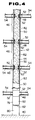
- FIG. 4 shows a concrete filled tube column according to the present invention, which is erected on a foundation 40 and constitutes a part of a building structure.
- This column has an outer tube 42 in which concrete is filled to form a concrete core 44.
- the outer tube 42 consists of a plurality of round steel tube pieces 46 coaxially joined in series.
- Each of the tube pieces 46 includes a joint tube 48 and a tube piece body 50 which is coaxially joined to the lower end of the joint tube 48.
- a plurality of bracket members in the form of H-steel bars 52 are welded to the outer face of the joint tube 48 so as to project radially outward from the outer face, and interconnect the joint tube 48 with beams 54 of the building structure.
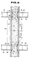
- Each H-steel bar 52 consists of upper and lower flange portions 56 and 58 and a web portion 60 interconnecting the upper and lower flange portions 56 and 58 (see FIG. 5).
- a tubular member 62 fits coaxially in the joint tube 48 and projects radially inward into the concrete core 44 in order to transfer the axial load from the joint tube 48 to the core 44.
- This tubular member 62 consists of: a pair of vertically spaced parallel inner flanges 64 and 66 circumferentially welded to the inner face of the joint tube 48; and a concrete layer 68 made of a high strength concrete circumferentially disposed on the inner face of the joint tube 48.
- Each of the inner flanges 64 and 66 is of a disk-like configuration having a central aperture and protrudes radially inward from the inner face of the joint tube 48.
- the upper inner flange 64 is positioned at the same level as the upper flange portions 56 of the bracket members 52, while the lower inner flange 66 is positioned at the same level as the lower flange portions 58 of the bracket members 52.
- the concrete layer 68 consists of three cylindrical portions, namely, first, second and third portions 70, 72 and 74.
- the first portion 70 is positioned under the lower inner flange 66 in such a manner that the upper end of the first portion 70 is in direct contact with the entire lower side of the first inner flange 66.
- This first portion 70 has an inner peripheral face 71 tapering upward so that the inner diameter at the upper end of the first portion 70 is generally equal to the inner diameter of the lower inner flange 66 and the inner diameter at the lower end of the first portion 70, i.e., the lower end of the tubular member 62 is generally equal to the inner diameter of the joint tube 48.
- the tapering angle ⁇ 1 of the inner peripheral face 71 with respect to the axis of the joint tube 48 is, preferably, in the range of 45° to 60°.
- the second portion 72 extends between the upper and lower inner flanges 64 and 66. This second portion 72 has an inner diameter generally equal to the inner diameters of the upper and lower inner flanges 64 and 66.
- the third portion 74 is positioned above the upper inner flange 64 in such a manner that the lower end of the third portion 74 is in direct contact with the entire upper side of the upper inner flange 64.
- This third portion 74 has an inner peripheral face 75 tapering downward so that the inner diameter at the lower end of the third portion 74 is generally equal to the inner diameter of the upper inner flange 64 and the inner diameter at the upper end of the third portion 74, i.e., the upper end of the tubular member 62 is generally equal to the inner diameter of the joint tube 48.
- the tapering angle ⁇ 2 of the inner peripheral face 75 with respect to the axis of the joint tube 48 is, preferably, in the range of 45° to 60°.
- the high strength concrete forming the concrete layer 68 has a compressive strength higher than the compressive strength of the concrete which forms the concrete core 44.
- a separating layer 76 is interposed between the concrete core 44 and the inner face of each tube piece 46 so that the core 44 is not bonded to the inner face of each tube piece 46.
- This separating layer 76 is made of a material such as asphalt, oil, grease, paraffin wax, petrolatum, synthetic resin and paper.
- the thickness of the separating layer 76 is such that it provides a viscous slip to the concrete core 44. In asphalt, the thickness is about 20 to 100 ⁇ m.
- the tube piece body 50 consists of upper and lower tubular sections 78 and 80.
- each of the upper and lower sections 78 and 80 are axially spaced apart from each other so that axial stress reducing means in the form of a ring-shaped gap 82 is formed between the upper and lower sections 78 and 80.
- the length of each of the upper and lower sections 78 and 80 is such that the gap 82 is positioned at the intermediate portion, that is, the inflection point of moment of the tube piece body 50. Since the separating layer 76 allows axial movement of each tube piece 46 relative to the core 44, the gap 82 varies its axial width W1 when each tube piece 46 is subjected to the axial load which is transmitted from the beams 54 of the building structure. Accordingly, an axial stress which develops in each tube piece 46 is reduced by the gap 82.
- the concrete core 44 is subjected to considerably more axial stress than the tube pieces 46 since the axial load applied to each tube piece 46 is transmitted to the core 44 via the upper and lower inner flanges 64 and 66 and the concrete layer 68.
- the outer tube 42 which is under considerably less stress than the core 44, provides the core 44 with sufficient lateral confinement, thereby effectively enhancing the axial compressive strength of the column.
- FIGS. 6 to 9 show a process for constructing the concrete filled tube column in FIG. 4.
- a plurality of precast structural tubes 84 are prepared in a factory.
- One of the precast structural tubes 84 is shown in FIG. 6.
- This structural tube 84 is manufactured in the following way: Three joint tubes 48 and three tube piece bodies 50 are prepared. Then, as shown in FIG. 7, the H-steel bars 52 are welded to the outer face of each of the prepared joint tubes 48, and the upper and lower inner flanges 64 and 66 are welded to the inner face of each of the prepared joint tubes 48. Thereafter, the concrete layer 68 is formed on the inner face of each joint tube 48 as shown in FIG. 8.
- This concrete layer 68 is formed by rotating the joint tube 48 slowly about its axis, and by manually spreading a high strength concrete on the inner face of the joint tube 48 so that the tapering inner peripheral faces 71 and 75 are formed respectively at the first and third portions 70 and 74 of the concrete layer 68.
- reinforcements may be provided along the inner face of the joint tube 48 to facilitate the application of the concrete.
- the concrete may be placed between the inner surface of the joint tube 48 and a cylindrical formwork which is detachably fixed to the inner face of the joint tube 48.
- the concrete layer 68 is formed by centrifugal molding.
- a pair of hollow truncated conical frameworks 86 are detachably fixed to the inner face of the joint tube 48 as shown by a phantom line in FIG. 8.
- the joint tube 48 is laid on a rotation machine in such a manner that the axis of the joint tube 48 extends substantially horizontally, and then the joint tube 48 is rotated about its axis at a high speed. Subsequently, a predetermined amount of high strength concrete is placed between the formworks 86. As a result, the concrete placed in the joint tube 48 is subjected to a centrifugal force due to the rotation of the tube piece 48, thereby being spread throughout the area between the frameworks 86 and forming the concrete layer 68.
- a clearance 88 may be formed between each framework 86 and the corresponding inner flange so that the concrete between the inner flanges 64 and 66 flows through the clearance 88 into the frameworks 86 during the rotation of the joint tube 48.
- through holes may be formed in the inner flanges 64 and 66 so as to allow the concrete to flow into the frameworks 86.
- the three joint tubes 48 are concentrically welded respectively to the upper ends of the three tube piece bodies 50 to form three tube pieces 46.
- three tube pieces 46 are coaxially joined in series to form the precast structural tube 84.
- the concrete layer 68 is formed after the welding of the inner flanges 64 and 66 and the H-steel bars 52 to the joint tube 48, the concrete layer 68 is not subjected to the heat due to the welding, and thereby the deterioration of the concrete layer 68 is prevented.
- the precast structural tubes manufactured as mentioned above are transported from the factory to a construction site, and there, one of the precast structural tubes 84 is erected on the foundation 40. Subsequently, as shown in FIG. 9, concrete is charged into the erected precast structural tube 84 by using, for example, a tremie 90 (which is a concrete-supplying pipe for conveying concrete) to form the concrete core 44. As the top face of the concrete approaches the inner peripheral face 71 of the concrete layer 68, air around the tapering inner peripheral face 71 flows upward smoothly along the inner peripheral face 71, and therefore the space under the inner peripheral face 71 is completely filled with the charged concrete.
- a tremie 90 which is a concrete-supplying pipe for conveying concrete
- each of the tube piece bodies 50 is separated into the upper and lower sections 78 and 80 by using a suitable cutter so that the gap 82 is formed between the upper and lower sections 78 and 80.
- the beams 54 of the building structure are joined respectively to the H-steel bars 52 of the precast structural tube 84, and then, another precast structural tube 84 is coaxially joined to the upper end of the concrete filled precast structural tube 84. Thereafter, the above-mentioned steps from the concrete-charging step to the precast tube-joining step are repeated predetermined times, which results in the construction of the concrete filled tube column.
- a precast structural tube having less than or more than three tube pieces 46 may be used for constructing the concrete filled tube column.
- another first portion 70 and another third portion 74 may be formed respectively under the upper inner flange 64 and above the lower inner flange 66.
- a tube piece body made of a carbon fiber reinforced concrete may be employed. This tube piece body consists of a hollow cylindrical cement matrix and a high strength carbon filament which is embedded within the cement matrix in such a manner that the carbon filament forms a coil coaxial with the cement matrix.
- Such a tube piece body is prepared by impregnating the carbon filament with a cement paste including cement particles of a particle size smaller than the diameter of the carbon filament and by forming the carbon filament into a cylindrical configuration.
- This fiber reinforced concrete tube piece body has a Young's modulus substantially equal to the Young' modulus of the concrete core 44, thereby providing the concrete core 44 with a sufficient lateral confinement even though neither the separating layer 76 nor stress reducing means 82 is disposed on the tube pieces.
- each of tube pieces 140 consists of a steel joint tube 142 and a steel tube piece body 50 concentrically welded to the lower end of the joint tube 142.
- the joint tube 142 has a steel tubular member integrally formed therewith, that is, the joint tube 142 has first and second tapering inner peripheral faces 71 and 75 formed respectively at its lower end upper ends. Therefore, the inner diameters at the upper and lower end of the joint tube 142 are equal to the inner diameter of the tube piece body 50, and the inner diameter of the central portion of the joint tube 142 is considerably smaller than that of the tube piece body 50.
- Each joint tube 142 is provided with a plurality of bracket members 52, while each tube piece body 50 is coated at its entire inner face with a separating layer 76. Needless to say, stress reducing means 82 is circumferentially disposed on the intermediate portion of each tube piece body 50.
- the joint tubes 142 are prepared, for example, by centrifugal casting, and therefore have roughened inner faces.
- the length L1 of each joint tube 142 is longer than sum of the height H1 of each bracket member 52 and the vertical length L2 of each tapering inner peripheral face.
- precast structural tubes each including a predetermined number of the joint tubes 142 and tube piece bodies 50 alternately joined in series
- the precast tubes are transported to a construction site, and they are connected one by one in the same manner as the manner of constructing the column in FIG. 4.
- this concrete filled tube column the generation of both the air spaces and the rock pockets are also prevented, and furthermore, the mechanical strength of each joint tube 142 is enhanced in comparison with the joint tubes of the foregoing embodiment.
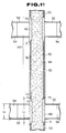
- a deformed reinforcing steel bar 144 may be axially disposed within the concrete core 44 as shown in FIG. 11.
- tube pieces have circular cross sections
- tube pieces having polygonal cross sections may be employed in places of the round tube pieces.
- the same concrete as the concrete constituting the core 44 is used for forming the concrete layers.
- a plurality of rows of through slots formed in the tube piece may be employed. Such through slots in a row are circumferentially disposed on the tube piece at angular intervals about the axis of the tube piece, and adjacent through slots of two adjacent rows are shifted in their positions in a zigzag manner.
Landscapes
- Engineering & Computer Science (AREA)
- Architecture (AREA)
- Structural Engineering (AREA)
- Civil Engineering (AREA)
- Life Sciences & Earth Sciences (AREA)
- Electromagnetism (AREA)
- Physics & Mathematics (AREA)
- General Life Sciences & Earth Sciences (AREA)
- Mining & Mineral Resources (AREA)
- Paleontology (AREA)
- General Engineering & Computer Science (AREA)
- Rod-Shaped Construction Members (AREA)
- Joining Of Building Structures In Genera (AREA)
- Revetment (AREA)
Claims (3)
- Tube de joint (48) destiné à être utilisé dans une colonne tubulaire remplie de béton et construite en sections (50) jointes coaxialement bout à bout au moyen du tube de joint, ce tube de joint comportant des moyens de transmission de charge (62) destinés à transmettre la charge axiale au noyau de béton (44) de la colonne, ces moyens de transmission de charge comprenant un élément tubulaire coaxial (62) comportant une surface d'engagement de noyau (71) allant en s'amincissant vers le haut dans la disposition verticale de la colonne, caractérisé en ce que l'élément tubulaire comporte également une surface d'engagement de noyau (75) allant en s'amincissant vers le bas.
- Tube de joint selon la revendication 1, caractérisé en ce que la partie ou les parties de l'élément allant en s'amincissant sont réalisées en béton ou autre matériau à base de ciment.
- Tube de joint selon la revendication 2, caractérisé en ce que l'élément tubulaire comprend :- une paire de collerettes annulaires constituée d'une collerette supérieure et d'une collerette inférieure faisant saillie vers l'intérieur sur une face intérieure du tube de joint; et- une couche de béton ou autre matériau à base de ciment formée entre la collerette supérieure et la collerette inférieure, du côté supérieur de la collerette supérieure, et du côté inférieur de la collerette inférieure, la couche formée du côté supérieur de la collerette supérieure constituant un collet destiné à former la surface d'engagement de noyau allant en s'amincissant vers le bas, et la couche formée du côté inférieur de la collerette inférieure constituant un collet destiné à former la surface d'engagement de noyau allant en s'amincissant vers le haut,
ce qui permet ainsi de réduire la tendance à la formation de poches autour des collerettes lorsqu'on remplit les sections tubulaires par le matériau de noyau, tout en réduisant également la tendance à d'autres effets indésirables au moment de la prise du matériau de noyau.
Applications Claiming Priority (4)
| Application Number | Priority Date | Filing Date | Title |
|---|---|---|---|
| JP234374/87 | 1987-09-18 | ||
| JP62234374A JPS6480638A (en) | 1987-09-18 | 1987-09-18 | Connection structure of packed steel-pipe concrete post |
| JP63080444A JPH01256651A (ja) | 1988-04-01 | 1988-04-01 | 鋼管コンクリート柱構造及びその施工方法 |
| JP80444/88 | 1988-04-01 |
Publications (2)
| Publication Number | Publication Date |
|---|---|
| EP0308038A1 EP0308038A1 (fr) | 1989-03-22 |
| EP0308038B1 true EP0308038B1 (fr) | 1993-09-15 |
Family
ID=26421454
Family Applications (1)
| Application Number | Title | Priority Date | Filing Date |
|---|---|---|---|
| EP88305320A Expired - Lifetime EP0308038B1 (fr) | 1987-09-18 | 1988-06-10 | Colonne en tube remplie de béton et son procédé de fabrication |
Country Status (5)
| Country | Link |
|---|---|
| EP (1) | EP0308038B1 (fr) |
| KR (1) | KR940009460B1 (fr) |
| CN (1) | CN1017364B (fr) |
| CA (1) | CA1300920C (fr) |
| DE (1) | DE3884117T2 (fr) |
Cited By (1)
| Publication number | Priority date | Publication date | Assignee | Title |
|---|---|---|---|---|
| CN102011432A (zh) * | 2010-11-24 | 2011-04-13 | 同济大学 | 新型多边形组合式钢管 |
Families Citing this family (10)
| Publication number | Priority date | Publication date | Assignee | Title |
|---|---|---|---|---|
| CA2213831C (fr) * | 1996-09-09 | 2001-12-04 | Finn A. Rasmussen | Pilier modulaire |
| RU2151247C1 (ru) * | 1998-08-05 | 2000-06-20 | Вологодский Политехнический Институт | Косвенная арматура |
| FI20085029L (fi) * | 2008-01-14 | 2009-07-15 | Rautaruukki Oyj | Menetelmä rakennusteollisuudessa käytettävän kuitubetonipilarin valmistamiseksi sekä kuitubetonipilari |
| CN101324115B (zh) * | 2008-07-04 | 2010-06-02 | 华南理工大学 | 钢管再生混合构件 |
| WO2011072451A1 (fr) * | 2009-12-17 | 2011-06-23 | Li Wenman | Modules de panneau pour assembler rapidement une maison et maison construite à partir de ceux-ci |
| JP6570973B2 (ja) * | 2015-11-10 | 2019-09-04 | 五洋建設株式会社 | トレミー管 |
| CN107246109B (zh) * | 2017-03-12 | 2019-04-16 | 东北石油大学 | 实复式钢管混凝土组合柱组合梁构成的框架及其施工方法 |
| CN111005737B (zh) * | 2019-12-28 | 2021-07-23 | 上海建旗建筑工程设计有限公司 | 一种隧道形式预应力管幕结构及施工方法 |
| CN113155555B (zh) * | 2020-01-23 | 2023-04-11 | 天津市政工程设计研究总院有限公司 | 用于模拟混凝土管廊的镁合金模型的制作方法 |
| CN111749346B (zh) * | 2020-06-30 | 2021-11-30 | 中国航空规划设计研究总院有限公司 | 一种含预制钢管混凝土芯柱构件的接长节点及施工方法 |
Family Cites Families (6)
| Publication number | Priority date | Publication date | Assignee | Title |
|---|---|---|---|---|
| GB287447A (en) * | 1927-03-19 | 1928-07-12 | Shojiro Takechi | Improvements in method and apparatus for concrete piling |
| US3963056A (en) * | 1974-01-02 | 1976-06-15 | Nippon Concrete Kogyo Kabushiki Kaisha | Concrete piles, poles or the like |
| DE3302075C2 (de) * | 1983-01-22 | 1985-05-09 | Rudolf Dipl.-Ing. 7000 Stuttgart Bergermann | Verbindung für Spannbeton- oder Stahlbetonbiegeträger |
| US4588327A (en) * | 1984-02-28 | 1986-05-13 | Lin Juei J | Precast concrete pile and method of placing it in the ground |
| CA1259808A (fr) * | 1985-03-05 | 1989-09-26 | Takanori Sato | Colonne tubulaire a remplissage de beton, et methode visant sa production |
| EP0218313B1 (fr) * | 1985-09-24 | 1991-06-26 | SHIMIZU CONSTRUCTION Co. LTD. | Colonne en tube d'acier remplie d'un matériau constructif |
-
1988
- 1988-06-06 CA CA000568735A patent/CA1300920C/fr not_active Expired - Fee Related
- 1988-06-10 EP EP88305320A patent/EP0308038B1/fr not_active Expired - Lifetime
- 1988-06-10 DE DE88305320T patent/DE3884117T2/de not_active Expired - Fee Related
- 1988-06-25 KR KR1019880007707A patent/KR940009460B1/ko not_active Expired - Lifetime
- 1988-07-30 CN CN88104690A patent/CN1017364B/zh not_active Expired
Cited By (2)
| Publication number | Priority date | Publication date | Assignee | Title |
|---|---|---|---|---|
| CN102011432A (zh) * | 2010-11-24 | 2011-04-13 | 同济大学 | 新型多边形组合式钢管 |
| CN102011432B (zh) * | 2010-11-24 | 2012-01-25 | 同济大学 | 多边形组合式钢管 |
Also Published As
| Publication number | Publication date |
|---|---|
| KR890005360A (ko) | 1989-05-13 |
| KR940009460B1 (ko) | 1994-10-13 |
| DE3884117T2 (de) | 1994-05-05 |
| CN1032375A (zh) | 1989-04-12 |
| DE3884117D1 (de) | 1993-10-21 |
| EP0308038A1 (fr) | 1989-03-22 |
| CN1017364B (zh) | 1992-07-08 |
| CA1300920C (fr) | 1992-05-19 |
Similar Documents
| Publication | Publication Date | Title |
|---|---|---|
| US4864797A (en) | Concrete filled tube column and method of constructing same | |
| CA1259808A (fr) | Colonne tubulaire a remplissage de beton, et methode visant sa production | |
| US5012622A (en) | Structural filler filled steel tube column | |
| CA1220046A (fr) | Organe de raccordement et de repartition des contraintes pour elements de construction en beton | |
| AT517959B1 (de) | Fundament für ein Windrad | |
| EP0308038A1 (fr) | Colonne en tube remplie de béton et son procédé de fabrication | |
| CN111042439A (zh) | 一种装配式混凝土建筑结构的预制柱及其梁柱节点 | |
| CN110725475A (zh) | 一种内置通高波纹管的预制柱及其框架结构及施工方法 | |
| EP0218313B1 (fr) | Colonne en tube d'acier remplie d'un matériau constructif | |
| CN112030720A (zh) | 预制盖梁与墩柱承插式连接结构及施工方法 | |
| EP0214800A2 (fr) | Poteau en tube d'acier avec remplissage | |
| GB2261456A (en) | A shoe for a concrete pile | |
| CN210315969U (zh) | 连接节点结构及装配式建筑 | |
| CN219793937U (zh) | 外环支撑的基坑支护结构 | |
| CN219175651U (zh) | 预制装配式混凝土空心柱 | |
| CN115595873B (zh) | 一种采用外包uhpc钢管连接的装配式混凝土桥墩及其施工方法 | |
| JP3320049B2 (ja) | 杭の製造方法 | |
| CN110206140A (zh) | 矩形钢管混凝土柱与混凝土梁的搭接节点 | |
| CN210562273U (zh) | 一种用于承载装配式电梯的地基 | |
| JP6640298B2 (ja) | 既製杭 | |
| CN219638132U (zh) | 混凝土梁与钢管柱的连接结构 | |
| CN223269204U (zh) | 一种桩头结构 | |
| JPH01315534A (ja) | アンボンド型プレキャスト鋼管コンクリート柱構造 | |
| CN224016622U (zh) | 一种带钢环拼接钢管连接的预制混凝土叠合柱及其连接结构 | |
| CN224016495U (zh) | 一种混凝土叠合柱及混凝土叠合柱结构体系 |
Legal Events
| Date | Code | Title | Description |
|---|---|---|---|
| PUAI | Public reference made under article 153(3) epc to a published international application that has entered the european phase |
Free format text: ORIGINAL CODE: 0009012 |
|
| AK | Designated contracting states |
Kind code of ref document: A1 Designated state(s): DE FR GB |
|
| 17P | Request for examination filed |
Effective date: 19890826 |
|
| 17Q | First examination report despatched |
Effective date: 19910207 |
|
| GRAA | (expected) grant |
Free format text: ORIGINAL CODE: 0009210 |
|
| AK | Designated contracting states |
Kind code of ref document: B1 Designated state(s): DE FR GB |
|
| REF | Corresponds to: |
Ref document number: 3884117 Country of ref document: DE Date of ref document: 19931021 |
|
| ET | Fr: translation filed | ||
| PG25 | Lapsed in a contracting state [announced via postgrant information from national office to epo] |
Ref country code: GB Effective date: 19940610 |
|
| PLBE | No opposition filed within time limit |
Free format text: ORIGINAL CODE: 0009261 |
|
| STAA | Information on the status of an ep patent application or granted ep patent |
Free format text: STATUS: NO OPPOSITION FILED WITHIN TIME LIMIT |
|
| 26N | No opposition filed | ||
| GBPC | Gb: european patent ceased through non-payment of renewal fee |
Effective date: 19940610 |
|
| PG25 | Lapsed in a contracting state [announced via postgrant information from national office to epo] |
Ref country code: FR Effective date: 19950228 |
|
| PG25 | Lapsed in a contracting state [announced via postgrant information from national office to epo] |
Ref country code: DE Effective date: 19950301 |
|
| REG | Reference to a national code |
Ref country code: FR Ref legal event code: ST |