EP0308163A2 - Abspulvorrichtung - Google Patents
Abspulvorrichtung Download PDFInfo
- Publication number
- EP0308163A2 EP0308163A2 EP88308417A EP88308417A EP0308163A2 EP 0308163 A2 EP0308163 A2 EP 0308163A2 EP 88308417 A EP88308417 A EP 88308417A EP 88308417 A EP88308417 A EP 88308417A EP 0308163 A2 EP0308163 A2 EP 0308163A2
- Authority
- EP
- European Patent Office
- Prior art keywords
- coil
- fluid
- rotation
- spindle
- guide
- Prior art date
- Legal status (The legal status is an assumption and is not a legal conclusion. Google has not performed a legal analysis and makes no representation as to the accuracy of the status listed.)
- Withdrawn
Links
Images


Classifications
-
- B—PERFORMING OPERATIONS; TRANSPORTING
- B23—MACHINE TOOLS; METAL-WORKING NOT OTHERWISE PROVIDED FOR
- B23K—SOLDERING OR UNSOLDERING; WELDING; CLADDING OR PLATING BY SOLDERING OR WELDING; CUTTING BY APPLYING HEAT LOCALLY, e.g. FLAME CUTTING; WORKING BY LASER BEAM
- B23K9/00—Arc welding or cutting
- B23K9/12—Automatic feeding or moving of electrodes or work for spot or seam welding or cutting
- B23K9/133—Means for feeding electrodes, e.g. drums, rolls, motors
- B23K9/1333—Dereeling means
Definitions
- This invention relates to improvements in de-reelers.
- These mechanisms otherwise referred to as coil unwinders, wire feeders, etc. have a wide range of applications, and are especially useful in feeding welding wire from a coil to an automatic welding machine.
- Machines which perform these functions have been known for some time, and can be classified according to the arrangement of the coil and the guiding device, i.e. whether the material is removed from the coil in a tangential direction, or in the axial direction of the coil.
- Such machines may be powered or unpowered.
- the motive force can be supplied by a rotary motor such as an electric or a fluid motor, or by a linear motor, e.g. a reciprocating pneumatic piston/cylinder unit.
- a power actuated de-reeler should be capable of:
- the machine should be capable of operating over a wide range of speeds without the need for adjustment, should be able to avoid breakage of the material in the event that the machine malfunctions or fails to operate properly, should facilitate loading and/or unloading of the coil, and should be of low cost, and if possible portable.
- De-reelers using rotary drive motors are relatively expensive because due to the large inertial forces that must be overcome in accelerating a heavy metal coil, e.g. of welding wire within the short time available, powerful and therefore expensive motors are required.
- De-reelers employing pneumatic or hydraulic linear actuator means while generally lower in cost, also have a number of drawbacks, and in particular have generally required relatively large actuators capable of accelerating the coil to the required speed within a single stroke of the actuator.
- the present invention provides a de-reeler adapted to support a coil of strand-like material and to unwind such material from the coil automatically on demand, said de-reeler comprising: a frame; a cradle mounted to rotate about an axis in said frame and adapted to receive the coil generally co-axially thereon; powered actuator means supported on said frame and operative to effect angular movement of said cradle and coil in one direction of rotation to unwind material from the coil; guide means pivotally mounted to move angularly about the axis of the coil to guide drawn-off material away from the coil in a given direction, said guide means being adapted to react to tension applied to the drawn-off material to move angularly in the other direction of rotation; sensor means adapted to respond to movement of the guide means in said other direction to energise said power-actuated means and rotate said coil in said one direction thereby to unwind additional material from the coil, such that when the rate at which additional material is unwound from said coil exceeds the
- the actuator means is a fluid powered piston cylinder unit coupled to drive the cradle through a ratchet mechanism.
- Supply of pressurized fluid to the piston cylinder unit is controlled by a fluid valve which is spring loaded to a position in which it permits pressurized fluid to be exhausted from the unit.
- the sensor means when actuated by the guide means urges the fluid valve to an active position wherein it directs pressurized fluid to the piston/cylinder unit to perform a power stroke, this linear stroke being converted to rotation of the cradle and coil through the ratchet mechanism.
- a proximity switch activated at the end of the power stroke causes the fluid valve to move to the exhaust position, the proximity switch being deacti vated at the end of the return stroke of the piston/cylinder unit.
- the guide means is preferably supported on a radial bail arm carried on a shaft that extends through the axial region of the coil and is continuously rotatable such that even when the coil is stationary, material can still be drawn off in the axial direction continuously through the guide means, the latter rotating through one complete revolution for each turn of material drawn off from the coil.
- the material can still be drawn off even if the powered actuator means should fail to function, although in this mode the drawn off material will not be drawn off in untwisted condition.
- the de-reeler comprises a frame 10 fabricated in sheet metal and of inverted U-shape having vertical side walls 11 spanned by a top plate 12 arranged at an angle of about 40° to the horizontal, the frame being open towards the front.
- Each sidewall 11 has an inclined front edge with upper and lower ends 14 and 15 that define angled corners.
- a support assembly 16 is centrally attached on the underside of the top plate 12 and comprises a pair of L-shaped brackets 17 attached to the top plate 12 by suitable fasteners 18 and supporting between them two axially spaced bearing assemblies 19.
- These bearing assemblies rotatably journal a cylindrical spindle 24 which projects forwardly and upwardly from the open front of the frame 10 and carries thereon a cradle 21.
- the cradle 21 is fixed to rotate with the spindle 24 and comprises a planar hub 22 having four radially extending arms 23, the outer end of each arm being angled upwardly as seen in Figure 1.
- the cradle 21 carried on the spindle 24 is rotatably mounted on an axis 25 parallel to the top plate 12 by the bearing assemblies 19.
- the spindle 24 extends between the bearing assemblies 19 through a ratchet housing 33 that carries a ratchet mechanism which is adapted to apply driving rotation to the spindle to effect rotation of the cradle.
- the ratchet housing 33 has a radially projecting arm 34 the distal end of which forms a pivotal connection through a pin 36 with one end of a link 35 the other end of which is pivotally connected to the end of a piston rod 37 of a pneumatic piston/cylinder unit 38.
- the casing of the piston/cylinder unit is carried on a fixed mounting plate 39 attached to the support assembly 16, the piston rod extending at right angles to the spindle axis 25 so that through the interaction of the pivoted link 35, extension or retraction movements of the piston rod 37 produce angular movement of the ratchet housing 33 about the axis 25.
- a ratchet mechanism 41 (illustrated only schematically) which is effective to couple the housing 33 to the spindle for joint rotation when the piston rod 37 is extended, and to interrupt such coupling when the piston rod is retracted so that the ratchet housing 33 is rotated relative to the spindle 24.
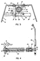
- the spindle 24 is of tubular form and as seen in Figure 4 wire guide rod 42 extends axially through the hollow interior of the spindle 24.
- Flanged bushings 43, 44 are positioned in opposite ends of the spindle 24 and provide bearings for rotation of the wire guard rod 42 relative to the spindle.
- the guide rod 42 projects beyond the distal end of the spindle and forms and driving connection to an end piece 45 by means of a grub screw 46.
- the end piece 45 carries a radially arranged bail arm 48 which is angled slightly downwardly at its outer end to define a wire guide loop 49.
- the wire guide rod 42 is thus arranged coaxially within the spindle 24, being supported therein at its upper end by a bearing 43 and at its lower end by the bearing 44.
- These bearings may suitably be nylon bushings.
- the wire guide rod 42 projects beyond the rear flanged bushing 44 and carries a valve disk 40 fixed to rotate with the guide rod.
- a rectangular notch 40a that opens from the periphery of the valve disk 40 is designed to cooperate with a pivotal actuator element of pneumatic start valve 51.
- clutch means 26 is provided to generate a controlled adjustable constant frictional resistance to relative rotation between the wire guide rod 42 and the spindle 24 to permit substantially unimpeded relative rotation when there is tension in the wire W. In the absence of tension in the wire W the clutch means 26 acts to cause the wire guide rod 42 to rotate with the spindle 24.
- the clutch 26 comprises two semi-cylindrical flanged half shells 27 positioned about the wire guide rod 42 in confronting relationship and surrounded by several turns of a coiled spring 28 having at one end a projecting arm 29 which is fixed to the spindle 24, as by a grub screw 30. In its free state the spring 28 has a diameter that is less than the diameter of the half shells 27, and accordingly when installed as shown in Figure 6a, the spring acts to exert a light pressing force of the half shells 27 upon the wire guide 42.
- the cradle 1 is adapted to support a coil 31 of welding wire or the like, the coil in this case being wound on a reel 32 received between the arms 23 and essentially coaxial with respect to the spindle 24.
- the wire W is threaded through the wire guide loop 49 to be drawn off in a generally axial direction with respect to the spool.
- Rotation of the cradle 21 and spool 32 is powered by the pneumatic piston/cylinder assembly 38.
- a brake 20 is actuated to terminate or prevent rotation of the cradle 21.
- the brake 20 is pneumatically operated and has a piston 20a which presses a brake pad 20b of a suitable frictional material against the underside of the cradle hub 22.
- the piston/cylinder unit 38 is of the single-acting type and performs a power stroke in which pressurized air moves the piston to extend the piston rod 37, the return stroke being effected by a spring 53.
- Pressurized air from a supply line 54 is passed to the cylinder 38 through a two-position four-way fluid control valve 55 and a two position three way fluid control valve 56 arranged in succession.
- the valve 55 is spring loaded to one position in which there is communication between the supply line 54 and the brake cylinder 20.
- the valve 56 is spring loaded to a position wherein the cylinder 38 is vented to atmosphere.
- the supply line 54 is also connected to a first pilot circuit 57 through a choke 58 which restricts air supply to the pilot circuit to a very low flow rate.
- the pilot circuit 57 when pressurized acts upon the control valve 55 to switch it to its second position wherein it supplies pressurized air to the valve 56 and to a second pilot circuit 59 having a choke 60.
- the first pilot circuit 57 is designed to be selectively vented or sealed by the start valve 51 whereas the second pilot circuit 59 is designed to be vented or sealed by the cycle valve 52.
- the associated flow control valve 55 or 56 prevents the supply of pressurized air from driving the cylinder 38 since the pilot circuit pressure cannot rise to a level sufficient to effect switching of the associated flow control valve.
- the start valve 51 is connected to a pivoted actuator element 50 one end of which extends into the notch 40a in the valve actuator disc 40 that is fixed to rotate with the rod 42.
- Rotation of the rod 42 in one direction that is corresponding to clockwise rotation of the bail arm 48 as seen in Figure 1, causes the disc 40 to interact with the element 50 to close the valve 51 and prevent escape of air therethrough.
- rotation of the rod 42 and disc 40 in the opposite direction causes the valve 51 to open and depressurize the first pilot circuit 57.
- the cycle valve 59 as illustrated in Figure 3 is fixedly mounted on the support assembly 16 and is adapted to be operated by adjustable cams 62 and 63 associated with the arm 34 of the ratchet housing 33.
- the cycle valve 52 acts as a proximity switch in that when the piston rod 37 completes its extension stroke, the cam 63 comes into engagement with the valve 52 to open it thus venting the second pilot circuit 59 and causing the control valve 56 to be moved to a position wherein the cylinder is exhausted allowing the piston rod to be retracted under the force of the spring 53.
- the cam 62 closes the valve 52 so that if the valve 51 is also closed, pressure can be built up in the pilot circuits 57, 59 to switch the control valve 56.
- the frame 10 of the de-reeler is tilted so that the edges 13 rest upon the floor and the open front is substantially vertical.
- the frame is moved towards the reel to pass the spindle through the core thereof so that the reel is received in the cradle 21 with the bent ends of the arm 23 extending over the periphery of the reel.
- the frame 10 is tilted about the corners 15 until the bottom edges of the sidewalls base plate 11 contact the floor.
- the reel 32 is thus supported in the position as shown in Figure 1, and its lower edge is spaced above the floor by virtue of the fact that the corners 15 are spaced away from the reel.
- the adjustable cam 63 opens the cycle valve 52 venting the pilot circuit 59 so that the control valve 56 switches to its second position connecting the cylinder unit 38 to exhaust and allowing the piston to be retracted under the force of the spring 53.
- the adjustable cam 62 engages and closes the cycle valve 52. If at this time the start valve 51 is still closed, as would occur if the amount of wire unwound by the preceding rotation of the spindle is not sufficient to slacken the wire W being drawn off, the pilot circuit 59 will again be pressurized to initiate another cycle of operation of the piston cylinder unit 38, and such cycles will be repeated until the start valve 51 is opened to vent the pilot circuit 57 and apply the brake 20.
- the force required to effect such slippage is the maximum force that it is needed to rotate the rod 42 and bail arm 48 relative to the spindle 24, and due to the configuration of the clutch means 26, this force will remain relatively constant over a wide range of speeds. If the tension in the wire being drawn off decreases, the spring 28 will attempt to regain its original form, closing the half shells 27 into increasing frictional engagement with the rod 42, causing the rod to rotate with the spindle 24 and opening the start valve 51. The tension required to draw off wire is determined by the nature of the spring 28 and the frictional characteristics of the half shells 27 and the rod 42. These properties may be selected to suit the material being fed. Because the clutch means 26 is inherently self regulating, it requires no adjustment to compensate for normal wear.
- Opening of the start valve 51 will thus occur when the de-reeler has unwound wire material in excess of the demand for the wire W being drawn off. In that event the tension in the wire W will be relieved thus allowing the bail arm 48 to be carried in the direction of rotation of the reel 32 (clockwise in Figure 1) thus rotating the rod 42 so that the disc 40 causes the start valve 51 to open. In the absence of tension in the drawn off wire W, the bail arm and rod 42 will be carried in the direction of movement of the reel by the frictional drag created through engagement of the clutch means 26 on the rod 42.
- Deceleration of the coil is effected by the frictional engagement of the pad 20b on the hub 22 when the brake 20 is actuated.
- the maximum feed rate of the welding wire would be about 1000 inches per minute which would correspond to a maximum speed of rotation of the spindle 24 of 100 rpm, the coil weight being in the range of 250 to 300 pounds.
- the piston 38 disclosed would have a bore of 1.5 inches and a stroke of 3 inches, operating at a pressure of 60-70 psi.
- the dimensions of the elements and the operating pressure of the cylinder can of course be changed to adapt to various conditions.
- the de-reeler can be provided in many different configurations, two alternative arrangements being illustrated in Figures 8 and 9 by way of example. In both of these embodiments the de-reeler is arranged with the spindle axis vertical.
- the de-reeler shown in Figure 8 is of a heavy duty variety designed to accept standard spools weighing up to 1,000 pounds. As shown, this de-reeler is also equipped to accept bulk coils of wire. As opposed to reels or spools, bulk coils are not wound onto spools or other supports, but rather are held in shape by bands of strapping wrapped around the coil.
- the de-reeler of Figure 8 is provided with a spool having a bottom flanged 70 connected to the disc shaped hub 22a and a separatable upper flange 71.
- the upper flange is removed, and the coil placed on the lower flange.
- the upper flange is then attached and the bands of strapping are severed to allow unwinding of the coil 72.
- the de-reeler unit shown in Figure 9 is designed to accept relatively a tall spool 32b as shown.
- the de-reeler is provided with a two part spindle, the upper spindle part 75 having a top end that passes through a flat triangular plate 76 above which the bail arm 48 is arranged to rotate.
- a pin 76a in the plate forms a driving connection with a recess (not shown) in the spool 32b.
- Immediately adjacent the triangular plate is an enlarged portion of the spindle in which the clutch means 26 is positioned.
- the wire guide rod 77 extends from the lower end of the upper spindle part 75 and is received in an elongated socket in an adjustable sleeve 78, the sleeve having a set screw (not shown) therein to engage the rod 77 at various positions along its length to accommodate the normal variations in the axial length of individual spools that may be encountered in use.
- the sleeve 78 has a flexible central section 79 and a lower end 80 defining a hollow coupling adapted to receive the end of the lower part 81 of the wire guide rod 77.
- the sleeve 78 is adjustable as indicated by the double arrow 82.
- the lower spindle part 83 and the associated lower wire guide rod part protrude 81 through the spool carrier cradle which is in the form of a flat circular plate 22b welded to the spindle.
- the protruding portion of the spindle part 83 serves to center the spool on the cradle.
- the de-reeler described above and illustrated in the accompanying drawings offers significant advantages over de-reelers of the prior art.
- it is of simplified low-cost construction and is portable, yet strong, being adapted for easy loading and unloading of coils of welding wire and the like.
- the de-reeler can operate over a large range of speeds without need for adjustment, the maximum speed being determined by the maximum possible rate of cycling of the piston cylinder unit 38.
- the maximum speed being determined by the maximum possible rate of cycling of the piston cylinder unit 38.
- wire in the event of malfunction of the de-reeler through failure of the piston/cylinder unit to operate to unwind wire from the coil, nonetheless wire can still be drawn off through the guide 49.
- the de-reeler of the present invention also improves over prior art designs in terms of stopping rotation of the coil once the demand for the material has ceased. Whereas in prior art designs various heaving duty braking arrangements were provided, in the present design the deceleration is accomplished by means of the relatively small and simple brake 20. The time available for deceleration of the coil is dependent upon the distance between the de-reeler and the machine being fed. During such deceleration the guide 49 will be carried along with the reel 32 applying a twist to the material which will be removed when the material is drawn off once more.
Landscapes
- Engineering & Computer Science (AREA)
- Physics & Mathematics (AREA)
- Plasma & Fusion (AREA)
- Mechanical Engineering (AREA)
- Tension Adjustment In Filamentary Materials (AREA)
- Winding Filamentary Materials (AREA)
- Unwinding Of Filamentary Materials (AREA)
Applications Claiming Priority (2)
| Application Number | Priority Date | Filing Date | Title |
|---|---|---|---|
| CA546641 | 1987-09-11 | ||
| CA546641 | 1987-09-11 |
Publications (2)
| Publication Number | Publication Date |
|---|---|
| EP0308163A2 true EP0308163A2 (de) | 1989-03-22 |
| EP0308163A3 EP0308163A3 (de) | 1990-05-30 |
Family
ID=4136417
Family Applications (1)
| Application Number | Title | Priority Date | Filing Date |
|---|---|---|---|
| EP88308417A Withdrawn EP0308163A3 (de) | 1987-09-11 | 1988-09-12 | Abspulvorrichtung |
Country Status (2)
| Country | Link |
|---|---|
| US (1) | US4934627A (de) |
| EP (1) | EP0308163A3 (de) |
Cited By (3)
| Publication number | Priority date | Publication date | Assignee | Title |
|---|---|---|---|---|
| FR2747600A1 (fr) * | 1996-04-23 | 1997-10-24 | Mig Weld | Devidoir de bobine de fil a souder, en particulier de fil d'aluminium |
| AT411341B (de) * | 1999-11-19 | 2003-12-29 | Fronius Schweissmasch Prod | Vorrichtung zum fördern von schweissdraht |
| CN114406569A (zh) * | 2022-01-21 | 2022-04-29 | 浙江盛越电子科技有限公司 | 一种空心杯马达全自动焊接机 |
Families Citing this family (6)
| Publication number | Priority date | Publication date | Assignee | Title |
|---|---|---|---|---|
| US5156355A (en) * | 1990-07-05 | 1992-10-20 | Ron Wadle | Winding and unwinding apparatus incorporating wrapping arms |
| USD332298S (en) | 1990-10-04 | 1993-01-05 | Logsdon Hartley T | Line despooler |
| IT1274555B (it) * | 1995-05-23 | 1997-07-17 | Lorenzo Massardi | Dispositivo di alimentazione di un filato,particolarmente un filato elastico,per macchine per maglieria,calzetteria o simili |
| US5948296A (en) * | 1998-02-23 | 1999-09-07 | Illinois Tool Works Inc. | Wire wheel adapter for mig welder |
| US6126102A (en) * | 1998-11-10 | 2000-10-03 | E. I. Du Pont De Nemours And Company | Apparatus for high speed beaming of elastomeric yarns |
| CN112047177B (zh) * | 2020-08-25 | 2022-05-20 | 深圳市鹏翔运达机械科技有限公司 | 一种线缆放线器 |
Family Cites Families (16)
| Publication number | Priority date | Publication date | Assignee | Title |
|---|---|---|---|---|
| CA549694A (en) * | 1957-12-03 | H. Friedman John | Stock reel drive mechanism | |
| CA855567A (en) * | 1970-11-10 | Kurtz Israel | Welding wire spool stand | |
| GB133781A (de) * | ||||
| CA875350A (en) * | 1971-07-13 | V. Rygiol Henry | Wire feeder | |
| CA692279A (en) * | 1964-08-11 | A. Van De Bilt Pieter | Wire-feeding apparatus for a machine, such as a packaging machine | |
| US2999654A (en) * | 1956-10-25 | 1961-09-12 | Mallory & Co Inc P R | Unwinding device |
| US2894657A (en) * | 1957-10-01 | 1959-07-14 | Dorothea A Griffin | Baby food warmer |
| US2942797A (en) * | 1957-11-14 | 1960-06-28 | Western Electric Co | Apparatus for handling spools of wire while the wire is being withdrawn therefrom |
| US3323752A (en) * | 1966-04-27 | 1967-06-06 | Sperry Rand Corp | Welding wire spool stand |
| FR93491E (fr) * | 1967-08-22 | 1969-04-04 | Lyonnaise De Classement Soc | Perfectionnements aux meubles de classement. |
| CA923098A (en) * | 1969-05-05 | 1973-03-20 | Satzinger Roland | Automatically controlled coil-unwinding device |
| DE1922781C3 (de) * | 1969-05-05 | 1981-11-05 | Alexandra 8730 Bad Kissingen Satzinger | Abwickelhaspel |
| US3815844A (en) * | 1972-03-20 | 1974-06-11 | Portland Chain Mfg Co | Method and apparatus for unwinding coiled material |
| DE2727813C2 (de) * | 1977-06-21 | 1982-11-11 | No-Sag Drahtfedern Gmbh, 4835 Rietberg | Vorrichtung zum Abspulen von Schweißdraht |
| GB1583750A (en) * | 1977-06-27 | 1981-02-04 | Scanway Eng Ltd | Welding apparatus |
| US4241884A (en) * | 1979-03-20 | 1980-12-30 | George Lynch | Powered device for controlling the rotation of a reel |
-
1988
- 1988-09-12 EP EP88308417A patent/EP0308163A3/de not_active Withdrawn
- 1988-09-12 US US07/243,043 patent/US4934627A/en not_active Expired - Fee Related
Cited By (6)
| Publication number | Priority date | Publication date | Assignee | Title |
|---|---|---|---|---|
| FR2747600A1 (fr) * | 1996-04-23 | 1997-10-24 | Mig Weld | Devidoir de bobine de fil a souder, en particulier de fil d'aluminium |
| EP0803310A1 (de) * | 1996-04-23 | 1997-10-29 | Mig Weld | Schweissdrahtvorschubgerät, insbesondere für Aluminiumdraht |
| AT411341B (de) * | 1999-11-19 | 2003-12-29 | Fronius Schweissmasch Prod | Vorrichtung zum fördern von schweissdraht |
| US6831251B1 (en) | 1999-11-19 | 2004-12-14 | Fronius International Gmbh | Welding rod drive unit with main and auxiliary drives |
| CN114406569A (zh) * | 2022-01-21 | 2022-04-29 | 浙江盛越电子科技有限公司 | 一种空心杯马达全自动焊接机 |
| CN114406569B (zh) * | 2022-01-21 | 2024-05-28 | 浙江盛越电子科技有限公司 | 一种空心杯马达全自动焊接机 |
Also Published As
| Publication number | Publication date |
|---|---|
| US4934627A (en) | 1990-06-19 |
| EP0308163A3 (de) | 1990-05-30 |
Similar Documents
| Publication | Publication Date | Title |
|---|---|---|
| US4241884A (en) | Powered device for controlling the rotation of a reel | |
| US5671912A (en) | Method & apparatus for providing low speed safety braking for a hoist system | |
| US4934627A (en) | De-reeler | |
| JP7036203B2 (ja) | 打込機 | |
| EP0288609A1 (de) | Aufwindevorrichtung für Reifenverstärkungsbänder | |
| US5007597A (en) | Automatic dispenser for elongated flexible coiled elements | |
| EP0810718A1 (de) | Drahttensor einer Maschine zum Wickeln der Spule einer dynamoelektrischen Maschine | |
| US4948325A (en) | Control apparatus for a loading-moving system | |
| JP2515385B2 (ja) | 印刷機のウエブ供給制御装置 | |
| CN103010820A (zh) | 纱线卷绕装置 | |
| CA1317580C (en) | De-reeler | |
| US3544029A (en) | Power-driven dispenser assembly | |
| US5354399A (en) | Method for setting bladder outer diameter of tire forming drum in a method for attaching belt-shaped member to the bladder | |
| CN101528575B (zh) | 用于制造交叉卷绕筒的纺织机的卷绕装置的筒子制动器 | |
| KR20010105348A (ko) | 중량물 리프팅 장치용 제어 시스템 및 방법 | |
| US4463911A (en) | Strap dispenser | |
| JPH06310353A (ja) | 巻線機におけるテンション付与機構及びテンション制御方法 | |
| US4965428A (en) | Wire electrical discharge machining apparatus | |
| US5186285A (en) | Method of, and a device for, controlling the rotation of an element about an axis by means of a wrap spring | |
| JP3358143B2 (ja) | 遠隔操作式巻取機のブレーキ装置 | |
| JPH06277756A (ja) | 線材の貯線装置 | |
| GB2350577A (en) | Automatic set-up wire drawer | |
| JP2000060407A (ja) | ホース繰出装置 | |
| GB2071802A (en) | Improvements relating to movement control devices | |
| KR20040033381A (ko) | 드럼브레이크를 갖는 호이스트 |
Legal Events
| Date | Code | Title | Description |
|---|---|---|---|
| PUAI | Public reference made under article 153(3) epc to a published international application that has entered the european phase |
Free format text: ORIGINAL CODE: 0009012 |
|
| AK | Designated contracting states |
Kind code of ref document: A2 Designated state(s): AT BE DE FR GB IT NL SE |
|
| PUAL | Search report despatched |
Free format text: ORIGINAL CODE: 0009013 |
|
| RHK1 | Main classification (correction) |
Ipc: B23K 9/12 |
|
| AK | Designated contracting states |
Kind code of ref document: A3 Designated state(s): AT BE DE FR GB IT NL SE |
|
| 17P | Request for examination filed |
Effective date: 19901126 |
|
| 17Q | First examination report despatched |
Effective date: 19910708 |
|
| STAA | Information on the status of an ep patent application or granted ep patent |
Free format text: STATUS: THE APPLICATION IS DEEMED TO BE WITHDRAWN |
|
| 18D | Application deemed to be withdrawn |
Effective date: 19930319 |