EP0308307A1 - Trennbare Verbindungsvorrichtung zwischen einem leitenden Stift und mindestens einem Verbindungsdraht - Google Patents
Trennbare Verbindungsvorrichtung zwischen einem leitenden Stift und mindestens einem Verbindungsdraht Download PDFInfo
- Publication number
- EP0308307A1 EP0308307A1 EP88402283A EP88402283A EP0308307A1 EP 0308307 A1 EP0308307 A1 EP 0308307A1 EP 88402283 A EP88402283 A EP 88402283A EP 88402283 A EP88402283 A EP 88402283A EP 0308307 A1 EP0308307 A1 EP 0308307A1
- Authority
- EP
- European Patent Office
- Prior art keywords
- clamp
- wire
- housing
- pin
- conductive
- Prior art date
- Legal status (The legal status is an assumption and is not a legal conclusion. Google has not performed a legal analysis and makes no representation as to the accuracy of the status listed.)
- Granted
Links
- 230000000750 progressive effect Effects 0.000 claims abstract description 4
- 239000003208 petroleum Substances 0.000 claims description 4
- 239000011810 insulating material Substances 0.000 claims description 3
- 239000000463 material Substances 0.000 claims description 3
- 230000037431 insertion Effects 0.000 claims 1
- 238000003780 insertion Methods 0.000 claims 1
- 238000009434 installation Methods 0.000 description 4
- 230000035515 penetration Effects 0.000 description 4
- 239000004020 conductor Substances 0.000 description 3
- 230000005540 biological transmission Effects 0.000 description 2
- 238000009413 insulation Methods 0.000 description 2
- 230000000712 assembly Effects 0.000 description 1
- 238000000429 assembly Methods 0.000 description 1
- 238000010586 diagram Methods 0.000 description 1
- 238000006073 displacement reaction Methods 0.000 description 1
- 230000000694 effects Effects 0.000 description 1
- 239000012212 insulator Substances 0.000 description 1
- 239000002184 metal Substances 0.000 description 1
- 238000000034 method Methods 0.000 description 1
- 230000003647 oxidation Effects 0.000 description 1
- 238000007254 oxidation reaction Methods 0.000 description 1
- 244000045947 parasite Species 0.000 description 1
- 230000001681 protective effect Effects 0.000 description 1
Images



Classifications
-
- H—ELECTRICITY
- H01—ELECTRIC ELEMENTS
- H01R—ELECTRICALLY-CONDUCTIVE CONNECTIONS; STRUCTURAL ASSOCIATIONS OF A PLURALITY OF MUTUALLY-INSULATED ELECTRICAL CONNECTING ELEMENTS; COUPLING DEVICES; CURRENT COLLECTORS
- H01R4/00—Electrically-conductive connections between two or more conductive members in direct contact, i.e. touching one another; Means for effecting or maintaining such contact; Electrically-conductive connections having two or more spaced connecting locations for conductors and using contact members penetrating insulation
- H01R4/24—Connections using contact members penetrating or cutting insulation or cable strands
- H01R4/2416—Connections using contact members penetrating or cutting insulation or cable strands the contact members having insulation-cutting edges, e.g. of tuning fork type
- H01R4/242—Connections using contact members penetrating or cutting insulation or cable strands the contact members having insulation-cutting edges, e.g. of tuning fork type the contact members being plates having a single slot
- H01R4/2425—Flat plates, e.g. multi-layered flat plates
- H01R4/2429—Flat plates, e.g. multi-layered flat plates mounted in an insulating base
- H01R4/2433—Flat plates, e.g. multi-layered flat plates mounted in an insulating base one part of the base being movable to push the cable into the slot
-
- Y—GENERAL TAGGING OF NEW TECHNOLOGICAL DEVELOPMENTS; GENERAL TAGGING OF CROSS-SECTIONAL TECHNOLOGIES SPANNING OVER SEVERAL SECTIONS OF THE IPC; TECHNICAL SUBJECTS COVERED BY FORMER USPC CROSS-REFERENCE ART COLLECTIONS [XRACs] AND DIGESTS
- Y10—TECHNICAL SUBJECTS COVERED BY FORMER USPC
- Y10S—TECHNICAL SUBJECTS COVERED BY FORMER USPC CROSS-REFERENCE ART COLLECTIONS [XRACs] AND DIGESTS
- Y10S439/00—Electrical connectors
- Y10S439/933—Special insulation
- Y10S439/936—Potting material or coating, e.g. grease, insulative coating, sealant or, adhesive
Definitions
- the present invention relates to a separable electrical connection device, mounted between a conductive pin permanently joined to a cable element or the like and at least one connecting wire joining this pin to another similar pin, located at a distance from the first.
- the sub-distribution strips are constituted by supports where the pins to be connected by the garters end, the conductive wires of these engaging transversely in passages formed in the support to be fixed on each some pins corresponding, being wound on them and immobilized by a nut screwing on the threaded end of the chosen spindle.
- each connection (a jumper has at least two wires which leads to connecting two by two at least four pins), requiring to strip the end of a wire and to secure it with the associated pin.
- the connections thus produced are generally made in the open air and are subject to working conditions which may lead to oxidation of the electrical contacts as a result of ambient humidity, possibly creating harmful short-circuits and more generally parasites (crackling) on the lines.
- the present invention relates to a separable connection device which makes it very easy to connect one or more jumpers to the conductive pins of a sub-distribution strip, in particular avoiding the drawbacks of the solutions already known in the art.
- the device considered is characterized in that it comprises means suitable for producing an electrical connection between at least one jumper wire having a conductive core surrounded by an insulating sheath and a conductive clip having at least one cutting slot. suitable for cutting the sheath of the wire as a result of it being inserted into the slot by establishing contact with the conductive core of the wire, means for ensuring the electrical connection between the clamp and the pin, and means for causing progressive engagement of the clamp on the wire.
- each slot made in an arm of the clamp has an enlarged part for positioning the wire prior to its engagement in the cutting slot of the clamp.
- the conductive clip is housed in a box receiving the conductive pin, this case being designed to contain a filling of an insulating protective material, surrounding the clamp and the wire.
- the insulating material consists of petroleum gel.
- each conductive pin has a threaded endpiece on which a nut is screwed which causes the movement of the clamp in the housing of its case.
- the nut comprises an overflowing flange, passing through a hole made in the clamp between the wings thereof, where the threaded end of the pin engages on which the nut is screwed, such so that removing it after being unscrewed from the spindle causes the clamp to come out of the case.
- the jumper wires engage in transverse passages provided in the clamp housing.
- each clamp has a male or female extension which forcibly engages in a respectively female or male part provided at the end of a connection pin, the clamp being enclosed in a housing independent of the pins and comprising a bottom and a cover, the positioning of the cover against the bottom ensuring the engagement of the connecting wires in the cutting slots of the pliers.
- the extension of the clamp extends beyond the apparent outline of the housing.
- the conductive pins penetrate directly inside the housing.
- the reference 1 designates as a whole a conventional distribution strip, comprising in particular a base 2, allowing its fixing on a support (not shown), by means of screws engaged in holes provided in the angles of basement.
- the strip 1 comprises a box 4, fixed to the base 2 by means of screws 5.
- This box 4 comprises, in its front face, housings 6 open towards the outside and in its lateral sides transverse passages 7a and 7b for mounting the wires of the connection jumpers.
- the second passage can be used in the case of a Y-mount, it is ie in the case where a second jumper must be connected to a specific pin.
- an axial pin 8 opens out inside each of the housings 6, this pin being connected by any conventional means to the end of a line 9, in particular for telephone use.
- connection wires 11a and 11b of a jumper In the transverse passages 7a 7b of the housing 4 are also engaged the connection wires 11a and 11b of a jumper, intended to provide the connection to another strip of conventional or similar type of a determined line, for example for connect the latter to an appropriate subscriber installation.
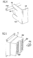
- the electrical connection is made quickly and safely by means of a connector device 10, which can be easily installed or separated from the housing 4 and of which Figures 3 and 6 respectively, illustrate two alternative embodiments.
- connection between pin and wires of the garter is made by means of a clamp 12, in the form of a jumper, the middle branch of which is suitable for engaging on the corresponding pin 8 while being arranged perpendicular to it.
- a clamp 12 in the form of a jumper, the middle branch of which is suitable for engaging on the corresponding pin 8 while being arranged perpendicular to it.
- the lateral branches 13 of this clamp they are then arranged parallel to this pin, therefore perpendicular to the passages 7a, 7b intended for the introduction of the wires of the corresponding garter.
- these wings 13 comprise, at the level of the wires 11a, 11b of the garter, cutting slots 14, making it possible to cut the insulating sheath of the wires 11a, 11b and to reach the core of the latter, by achieving the continuity of the connection electric with pin 8.
- the central part of the clamp 12 is integral with a metal sleeve 16, on which is mounted an operating head 17 of plastic or other material.
- This sleeve has a flange 18 projecting under the clamp so that the latter and the head 17 are secured in axial displacement, while allowing the free rotation of this head as the clamp 12 engages in the housing 6.
- the sleeve 16 has an internal screw thread 19, suitable for cooperating with a thread 20 provided at the end of the spindle 8.
- the rotation of the head 17 by means of a tool for controlling the such as a screwdriver engaged in a slot 21, makes it possible to simultaneously rotate the sleeve 16 which screws onto the spindle, causing the desired progressive engagement of the clamp 12 between the same of these wires and the spindle.
- each housing 6 has two recesses 13a intended to receive the ends of the lateral wings 13 of the corresponding connection clamp 12.
- connection pliers 12 which differ in the length of their lateral wings 13, those of the pliers having to cooperate with wires 11a, 11b, placed in the passages 7a, 7b, the most separated from the face. front of the housing 4, being longer than the wings 13 of the other series of connection clamps.
- a housing 4a comprising a series of superimposed cells 22 inside each of which are arranged two pins 8 connected to lines not shown. These cells can be divided into two separate vertical rows, the front face of the housing 4a having a recess between these two rows.
- a closure cap 23 When no connection is made at the location of a cell 22, the latter is closed by a closure cap 23. Once the latter has been removed, the connection between the wires 11a and 11b of a jumper and the pin 8 of the corresponding socket 22 is produced by a socket 24, comprising lateral sides 25 and an inner face 26, itself crossed by hollow rods 27. In the example considered, these are among of two and suitable for engaging, by establishing the desired electrical connection, inside bores 28, provided axially in the pins 8.
- the hollow rods 27 extend inside the socket 24 by a clamp 29, having a perpendicular rim 30, provided with vertical cutting slots 31, these having at their ends enlarged zones 32 to facilitate the engagement of the wires 11a and 11b, the insulation of which is then stripped by the slots 31, the electrical connection with the pins being thus established.
- the clamp 29 has two parallel edges 30 and 33.
- the trunk 24 of the socket it has a bottom 34 comprising passages 7a and 7b for the introduction of the wires of the garter; a hinged cover 35 supports towards the inside of the socket a support plate 36 intended, when the socket is closed by the cover, to rest on the wires 11a and 11b, making them penetrate into the slots 31 of the pliers 29. Stops 37 and 38 are preferably provided on the cover 35 to limit the penetration of the latter and the penetration of the socket 24 in the housing 22.
- the interior of the socket 24 is preferably filled, as in the previous example with insulating petroleum gel.
- each socket 24 contains two connection clamps 29 for possible mounting in Y, that is to say for mounting a second jumper.
- a very simple connection device is thus produced, making it possible to safely and quickly connect the wires of a jumper and the connecting pins d '' a distribution strip, by engagement of a socket or the like in an appropriate housing of a box, this socket carrying at least one cutting pliers stripping the insulation of these wires to establish the desired electrical contact and / or inter-express it this on demand, depending on the connections to be made.
- the invention does not prejudge in particular the shape of the housings and the cutter pliers which can be produced in various ways without modifying the process involved; the provisions envisaged provide in all cases an excellent seal for the boxes or connection sockets used, avoiding the effects of humidity, the cutter pliers being housed in closed assemblies and embedded in an appropriate insulator.
Landscapes
- Connections Effected By Soldering, Adhesion, Or Permanent Deformation (AREA)
- Connections By Means Of Piercing Elements, Nuts, Or Screws (AREA)
- Connections Arranged To Contact A Plurality Of Conductors (AREA)
Applications Claiming Priority (2)
| Application Number | Priority Date | Filing Date | Title |
|---|---|---|---|
| FR8712977A FR2620870B1 (fr) | 1987-09-18 | 1987-09-18 | Dispositif de liaison separable entre une broche conductrice et au moins un fil de connexion |
| FR8712977 | 1987-09-18 |
Publications (2)
| Publication Number | Publication Date |
|---|---|
| EP0308307A1 true EP0308307A1 (de) | 1989-03-22 |
| EP0308307B1 EP0308307B1 (de) | 1994-06-15 |
Family
ID=9355051
Family Applications (1)
| Application Number | Title | Priority Date | Filing Date |
|---|---|---|---|
| EP88402283A Expired - Lifetime EP0308307B1 (de) | 1987-09-18 | 1988-09-09 | Trennbare Verbindungsvorrichtung zwischen einem leitenden Stift und mindestens einem Verbindungsdraht |
Country Status (4)
| Country | Link |
|---|---|
| US (1) | US4917633A (de) |
| EP (1) | EP0308307B1 (de) |
| DE (1) | DE3850198T2 (de) |
| FR (1) | FR2620870B1 (de) |
Families Citing this family (7)
| Publication number | Priority date | Publication date | Assignee | Title |
|---|---|---|---|---|
| US5090917A (en) * | 1991-05-10 | 1992-02-25 | Thomas & Betts Corporation | Insulation displacing connector for providing repeatable sealed termination of electrical conductors |
| US5139440A (en) * | 1991-06-26 | 1992-08-18 | Reliance Comm/Tec Corporation | Environmentally sealed insulation displacement connector terminal block |
| EP0632527B1 (de) * | 1993-06-29 | 1999-01-20 | KRONE Aktiengesellschaft | Anschlussmodul |
| US5368501A (en) * | 1993-12-06 | 1994-11-29 | Georgia Tech Research Corporation | Rotary actuated, enviromental, insulation displacement connector |
| CN1107359C (zh) * | 1998-12-11 | 2003-04-30 | 富士康(昆山)电脑接插件有限公司 | 一种连接器连线装置及其连线方法 |
| WO2011019466A1 (en) * | 2009-08-11 | 2011-02-17 | Illinois Tool Works Inc. | Insulation displacement terminal system with regulated wire compression |
| JP6774627B2 (ja) * | 2016-11-11 | 2020-10-28 | 住友電装株式会社 | 電線の接合構造及びワイヤハーネス |
Citations (2)
| Publication number | Priority date | Publication date | Assignee | Title |
|---|---|---|---|---|
| FR2144322A5 (de) * | 1971-06-28 | 1973-02-09 | Minnesota Mining & Mfg | |
| GB2115992A (en) * | 1982-03-01 | 1983-09-14 | Minnesota Mining & Mfg | Drop wire connector with insulation-displacing contacts |
Family Cites Families (8)
| Publication number | Priority date | Publication date | Assignee | Title |
|---|---|---|---|---|
| CA481232A (en) * | 1952-02-19 | Stewart Mclarn Ernest | Telephone cord connector | |
| GB618755A (en) * | 1946-12-03 | 1949-02-25 | Ian Murray Ross | Improvements in or relating to electrical terminals |
| US2672595A (en) * | 1952-12-05 | 1954-03-16 | Gen Electric | Electrical cable clamp |
| US2740100A (en) * | 1953-08-24 | 1956-03-27 | Gen Electric | Electrical cable clamp |
| CH460106A (fr) * | 1966-07-29 | 1968-07-31 | Fontainemelon Horlogerie | Pince de contact pour fil conducteur |
| US3960427A (en) * | 1974-10-31 | 1976-06-01 | I.C.M. Industries, Inc. | Retainer for an end fitting of a welding cable |
| FR2541049B1 (fr) * | 1983-02-15 | 1985-09-13 | Faucigny Communication | Dispositif de connexion autodenudant |
| US4645285A (en) * | 1985-08-26 | 1987-02-24 | Amp Incorporated | Sealed insulation displacement connector |
-
1987
- 1987-09-18 FR FR8712977A patent/FR2620870B1/fr not_active Expired - Lifetime
-
1988
- 1988-09-09 EP EP88402283A patent/EP0308307B1/de not_active Expired - Lifetime
- 1988-09-09 DE DE3850198T patent/DE3850198T2/de not_active Expired - Fee Related
- 1988-09-15 US US07/244,884 patent/US4917633A/en not_active Expired - Fee Related
Patent Citations (2)
| Publication number | Priority date | Publication date | Assignee | Title |
|---|---|---|---|---|
| FR2144322A5 (de) * | 1971-06-28 | 1973-02-09 | Minnesota Mining & Mfg | |
| GB2115992A (en) * | 1982-03-01 | 1983-09-14 | Minnesota Mining & Mfg | Drop wire connector with insulation-displacing contacts |
Also Published As
| Publication number | Publication date |
|---|---|
| DE3850198T2 (de) | 1994-10-13 |
| FR2620870B1 (fr) | 1990-01-05 |
| DE3850198D1 (de) | 1994-07-21 |
| US4917633A (en) | 1990-04-17 |
| EP0308307B1 (de) | 1994-06-15 |
| FR2620870A1 (fr) | 1989-03-24 |
Similar Documents
| Publication | Publication Date | Title |
|---|---|---|
| FR2504315A1 (fr) | Element de connexion et dispositif de connexion, comportant de tels elements | |
| EP0308307B1 (de) | Trennbare Verbindungsvorrichtung zwischen einem leitenden Stift und mindestens einem Verbindungsdraht | |
| FR2568439A1 (fr) | Dispositif de connexion pour un element chauffant electrique en cartouche | |
| EP0684662A1 (de) | Schneidklemmverbinder | |
| BE1010843A5 (fr) | Boite de raccordement pour un reseau informatique. | |
| EP0805605A1 (de) | Abzweigverbinder für Übertragungsnetze, insbesondere für die Telephonie und Datenverarbeitung | |
| EP3477789B1 (de) | Adapter für abgeschirmten steckverbinder, abgeschirmter steckverbinder und montageverfahren eines solchen abgeschirmten steckverbinders | |
| EP0392422A1 (de) | Verfahren zum Abzweigen und Festklemmen eines mehradrigen, abgeschirmten elektrischen Kabelstranges und Verbinder hierfür | |
| EP0251909B2 (de) | Verbindungselement für ein elektrisches Monoleiterkabel zur axialen Verbindung | |
| EP0306913B1 (de) | Abzweigungsverbinder für koaxiale Kabel | |
| FR2947672A1 (fr) | Ensemble de connexions | |
| EP2135326A1 (de) | Leitfähige vorrichtung für den elektrischen kontakt einer leiterabschirmungsummantelung | |
| EP2503644B1 (de) | Elektrogerät von Klemmenleiste Typ | |
| WO1986003063A1 (fr) | Dispositif de connexion | |
| EP3490073A1 (de) | Elektrische anschlussvorrichtung zur erdung | |
| FR2600217A1 (fr) | Connecteur de piquage cable coaxial et obturateur de substitution correspondant | |
| FR2819348A1 (fr) | Connexion autodenudante a fente convergente | |
| FR2714219A1 (fr) | Bornier pour connecteur de distribution et connecteur de distribution correspondant. | |
| FR2751482A1 (fr) | Dispositif pour la realisation d'une epissure | |
| EP0732768A1 (de) | Verfahren zur Herstellung einer elektrischen Verbindung mit einer metallenen Abschirmung eines Energiekabels und Ring zur Durchführung des Verfahrens | |
| EP0779678A1 (de) | Elektrischer Kabelsteckverbinder zum Anschliessen einen leitenden Teil, insbesondere für elektrische Kabel ausgerüstet mit Kabelendstück | |
| FR2692408A1 (fr) | Connecteur mâle pour réseau de communication informatique et/ou téléphonique. | |
| FR3061811A1 (fr) | Kit de raccordement electrique ameliore | |
| WO1983002690A1 (fr) | Connecteur electrique plat a trois broches | |
| BE857590R (fr) | Connecteur pour cable plat |
Legal Events
| Date | Code | Title | Description |
|---|---|---|---|
| PUAI | Public reference made under article 153(3) epc to a published international application that has entered the european phase |
Free format text: ORIGINAL CODE: 0009012 |
|
| AK | Designated contracting states |
Kind code of ref document: A1 Designated state(s): DE ES GB IT |
|
| 17P | Request for examination filed |
Effective date: 19890705 |
|
| 17Q | First examination report despatched |
Effective date: 19920609 |
|
| RAP1 | Party data changed (applicant data changed or rights of an application transferred) |
Owner name: CENTRE NATIONAL D'ETUDES DES TELECOMMUNICATIONS |
|
| GRAA | (expected) grant |
Free format text: ORIGINAL CODE: 0009210 |
|
| AK | Designated contracting states |
Kind code of ref document: B1 Designated state(s): DE ES GB IT |
|
| PG25 | Lapsed in a contracting state [announced via postgrant information from national office to epo] |
Ref country code: IT Free format text: LAPSE BECAUSE OF FAILURE TO SUBMIT A TRANSLATION OF THE DESCRIPTION OR TO PAY THE FEE WITHIN THE PRE;WARNING: LAPSES OF ITALIAN PATENTS WITH EFFECTIVE DATE BEFORE 2007 MAY HAVE OCCURRED AT ANY TIME BEFORE 2007. THE CORRECT EFFECTIVE DATE MAY BE DIFFERENT FROM THE ONE RECORDED.SCRIBED TIME-LIMIT Effective date: 19940615 Ref country code: ES Free format text: THE PATENT HAS BEEN ANNULLED BY A DECISION OF A NATIONAL AUTHORITY Effective date: 19940615 |
|
| GBT | Gb: translation of ep patent filed (gb section 77(6)(a)/1977) |
Effective date: 19940615 |
|
| REF | Corresponds to: |
Ref document number: 3850198 Country of ref document: DE Date of ref document: 19940721 |
|
| PGFP | Annual fee paid to national office [announced via postgrant information from national office to epo] |
Ref country code: DE Payment date: 19940919 Year of fee payment: 7 Ref country code: GB Payment date: 19940919 Year of fee payment: 7 |
|
| PLBE | No opposition filed within time limit |
Free format text: ORIGINAL CODE: 0009261 |
|
| STAA | Information on the status of an ep patent application or granted ep patent |
Free format text: STATUS: NO OPPOSITION FILED WITHIN TIME LIMIT |
|
| 26N | No opposition filed | ||
| PG25 | Lapsed in a contracting state [announced via postgrant information from national office to epo] |
Ref country code: GB Effective date: 19950909 |
|
| GBPC | Gb: european patent ceased through non-payment of renewal fee |
Effective date: 19950909 |
|
| PG25 | Lapsed in a contracting state [announced via postgrant information from national office to epo] |
Ref country code: DE Effective date: 19960601 |