EP0308351A2 - Längenveränderbare Strebe mit pneumatischer Steuerung, und Verwendung als Stütze, zum Beispiel für ein Krankenhausbett - Google Patents
Längenveränderbare Strebe mit pneumatischer Steuerung, und Verwendung als Stütze, zum Beispiel für ein Krankenhausbett Download PDFInfo
- Publication number
- EP0308351A2 EP0308351A2 EP88402361A EP88402361A EP0308351A2 EP 0308351 A2 EP0308351 A2 EP 0308351A2 EP 88402361 A EP88402361 A EP 88402361A EP 88402361 A EP88402361 A EP 88402361A EP 0308351 A2 EP0308351 A2 EP 0308351A2
- Authority
- EP
- European Patent Office
- Prior art keywords
- support
- articulated
- rods
- tubular body
- male
- Prior art date
- Legal status (The legal status is an assumption and is not a legal conclusion. Google has not performed a legal analysis and makes no representation as to the accuracy of the status listed.)
- Withdrawn
Links
- 239000012528 membrane Substances 0.000 claims abstract description 11
- 230000001360 synchronised effect Effects 0.000 claims description 4
- 238000005452 bending Methods 0.000 claims description 2
- 238000002513 implantation Methods 0.000 claims description 2
- 238000004904 shortening Methods 0.000 abstract description 5
- 238000012423 maintenance Methods 0.000 description 7
- 230000000903 blocking effect Effects 0.000 description 2
- 238000006073 displacement reaction Methods 0.000 description 2
- 230000000474 nursing effect Effects 0.000 description 2
- 238000004873 anchoring Methods 0.000 description 1
- 230000008602 contraction Effects 0.000 description 1
- 230000003247 decreasing effect Effects 0.000 description 1
- 230000000881 depressing effect Effects 0.000 description 1
- 230000009977 dual effect Effects 0.000 description 1
- 238000003780 insertion Methods 0.000 description 1
- 230000037431 insertion Effects 0.000 description 1
- 238000009434 installation Methods 0.000 description 1
- 238000007665 sagging Methods 0.000 description 1
- 238000007789 sealing Methods 0.000 description 1
Images


Classifications
-
- B—PERFORMING OPERATIONS; TRANSPORTING
- B66—HOISTING; LIFTING; HAULING
- B66F—HOISTING, LIFTING, HAULING OR PUSHING, NOT OTHERWISE PROVIDED FOR, e.g. DEVICES WHICH APPLY A LIFTING OR PUSHING FORCE DIRECTLY TO THE SURFACE OF A LOAD
- B66F7/00—Lifting frames, e.g. for lifting vehicles; Platform lifts
- B66F7/06—Lifting frames, e.g. for lifting vehicles; Platform lifts with platforms supported by levers for vertical movement
- B66F7/08—Lifting frames, e.g. for lifting vehicles; Platform lifts with platforms supported by levers for vertical movement hydraulically or pneumatically operated
- B66F7/085—Lifting frames, e.g. for lifting vehicles; Platform lifts with platforms supported by levers for vertical movement hydraulically or pneumatically operated pneumatically operated
-
- A—HUMAN NECESSITIES
- A47—FURNITURE; DOMESTIC ARTICLES OR APPLIANCES; COFFEE MILLS; SPICE MILLS; SUCTION CLEANERS IN GENERAL
- A47B—TABLES; DESKS; OFFICE FURNITURE; CABINETS; DRAWERS; GENERAL DETAILS OF FURNITURE
- A47B91/00—Feet for furniture in general
- A47B91/02—Adjustable feet
-
- B—PERFORMING OPERATIONS; TRANSPORTING
- B66—HOISTING; LIFTING; HAULING
- B66F—HOISTING, LIFTING, HAULING OR PUSHING, NOT OTHERWISE PROVIDED FOR, e.g. DEVICES WHICH APPLY A LIFTING OR PUSHING FORCE DIRECTLY TO THE SURFACE OF A LOAD
- B66F7/00—Lifting frames, e.g. for lifting vehicles; Platform lifts
- B66F7/06—Lifting frames, e.g. for lifting vehicles; Platform lifts with platforms supported by levers for vertical movement
- B66F7/065—Scissor linkages, i.e. X-configuration
- B66F7/0666—Multiple scissor linkages vertically arranged
-
- B—PERFORMING OPERATIONS; TRANSPORTING
- B66—HOISTING; LIFTING; HAULING
- B66F—HOISTING, LIFTING, HAULING OR PUSHING, NOT OTHERWISE PROVIDED FOR, e.g. DEVICES WHICH APPLY A LIFTING OR PUSHING FORCE DIRECTLY TO THE SURFACE OF A LOAD
- B66F7/00—Lifting frames, e.g. for lifting vehicles; Platform lifts
- B66F7/06—Lifting frames, e.g. for lifting vehicles; Platform lifts with platforms supported by levers for vertical movement
- B66F7/08—Lifting frames, e.g. for lifting vehicles; Platform lifts with platforms supported by levers for vertical movement hydraulically or pneumatically operated
Definitions
- the present application relates to an expandable pneumatically controlled support, of the type comprising an air chamber actuating the elongation of a vertical device articulated in an accordion, such a device being in particular intended to allow lifting of loads, or more particularly, allowing the proclive / declive and / or the elevation of a bed / box spring, to facilitate the use of the elderly or disabled, as well as to reduce in hospital, the effort of the nursing staff, when handling patients , and the maintenance of the surfaces under the bed / box spring, by the maintenance staff.
- the beds pre-equipped for their raising and declination / declination are either actuated by mechanical devices, or by electrical or hydro-pneumatic devices. In general they require lever arms, and therefore, their installation is heavy and bulky. In addition, when the actuating means are electric, they are expensive. Whatever they are, these devices are not suitable for equipping fixed level beds.
- a telescopic device as described in patent application No. 8407717, as being capable of being actuated only by manually lifting the bed base or bed, is also not, in principle, adapted to the weight of the medical beds and paramedical, and therefore does not meet the ergonomic criteria applying to the tasks of nursing staff and community maintenance or operating in the context of hospitalization at home.
- Pneumatic systems using bellows are also known, such as the devices based on flexible cylinders covered by patents No. FR-A-2 146098, US-A-2 610824 and FR-A-2 405209, as 'exerting a vertical thrust on a horizontal plane maintained by braces and half-braces, do not respond to the problem posed, taking into account the number of tubular bellows required, given the useful stroke of each of them, for a given diameter, given their bulk due to the surface of the intermediate plates, extending significantly from the maximum section of the bellows, to give lateral stability to the assembly, this decreasing nevertheless with the number of intermediate plates and therefore the importance extension of the system.
- the device according to the invention avoids these drawbacks and thus makes it possible to provide a device adaptable to beds with a fixed level, as well as serving as a support for beds with variable level.
- two of them arranged in trestles of variable height, make it possible to provide support for the lower horizontal part of the bed. They allow the height adjustment of the sleeping surface, by the use of a low power air pump. They ensure over long periods, by the sealing of their air chamber, the maintenance of the desired position. They have a restricted gauge compared to that of other load lifting devices, in particular bellows-based, the thrust of which is effected vertically.
- the object of the invention consists of an air chamber, of the type constituted by a membrane moving in a cylindrical chamber, and actuating a rod guided by the body of said chamber, and which actuates laterally a plate acting on articulated panels arranged symmetrically, and articulated in their crossing zone by axes, defining parallelograms of a type known per se, extending over the entire height of the male and female element of the device, and thereby ensuring the maintenance parallelism between the plate and the opposite face of the male element.
- the structure according to the invention provides an air chamber, disposed outside the tubular body, and constituted by the inner surface of a cylinder externally integral with the tubular body and the surface of a flexible membrane, the variations of the elongation of the membrane at the central part of this chamber causing, by a lateral displacement of a system for supporting the membrane on a sliding rod forming piston / piston rod itself / then head of said piston (this the latter being integrated into the tubular body and either kept parallel to the wall opposite it in the tubular body, or secured to the "piston" rod through a joint (for example a ball joint), the elongation / the shortening of a system of articulated panels of small width, in accordion, supplemented with symmetrical panels, also articulated between them at their ends and on the other hand articulated at first in their mid-crossing zone -length of said sides, so as to define the cross-pieces of a set of deformable parallelograms.
- a joint for example a ball joint
- Maintaining the parallelism of the movable plate is, when the "piston" rod is integral with the plate, directly ensured by the piston rod of the air chamber on the one hand, and above all by the system of deformable parallelograms which moreover, thanks to its autonomy in terms of guidance during the final phase of elongation outside the movable plate, an increase in elongation without increasing the size.
- a stop / guide integral with the internal horizontal wall of the female element of the body is added a stop / guide integral with the internal horizontal wall of the female element of the body, this stop being preferably telescopic, and in this case also integral of the internal horizontal wall of the male element of the support, thus avoiding the bending of the system of braces and therefore of the extensible support as a whole.
- the articulated flaps arranged outside the flange guide zone during maximum extension, are of reduced length by with respect to the articulated panels disposed inside this guide zone.
- the retraction of the sections provided of equal length in their guide means in the shortening phase of the device can also be facilitated by the flaring at the same time of the upper end of the vertical lateral thrust plate, disposed at the end of the piston rod, and the opposite wall of the male tubular body, to maximize the efficiency of the lateral actuation of the articulated sections.
- the implantation of the rod actuated by the air chamber is provided in the middle part of the height of the stack of those of the folded articulated panels which remain in the zone for guiding the panels during maximum extension.
- the panels constituting the system of articulated panels of small width and defining the parallelograms of the extendable system are, in the vertical direction, alternately single and double, with opposite arrangement of the double and single panels opposite, of so as to reduce the number of sides' arms by a quarter, while preventing the system from flexing.
- two devices according to the invention can be associated and their extension synchronized by the insertion of the air chambers of each of them , in a tubular body of square or rectangular section, and by placing them head to tail, with the bottoms of the cylinders arranged opposite, and the rods exiting in opposite directions each towards the corresponding legs, the synchronism of the movements being obtained by the interposition on the rods, of means of articulation of one of the ends, of rods whose other end is articulated at the base of a sliding rod in a vertical median plane, the rods whose movement is synchronized, sliding in guide rings arranged on the lateral faces of the tubular body and of the male part of the telescopic devices.
- a single cylinder device in which two membranes are provided on either side of a central intake, can be used in place of the two separate cylinders.
- each telescopic support with variable height comprises supports with vertical elongation, the upper end of which takes the form of a semi-cylindrical bearing, the axis of which is oriented parallel to the piston rods which actuate the thrust surfaces, this form making it possible to maintain a constant linear support, of the bed frame or box spring moving on said span, connection means being further provided.
- the dual control device comprises a means of blocking and unblocking, by central or manual control, at least one of the orientable casters provided at the base of the base, this blocking and unblocking being obtained by the presence on the at least one piston rod, and integral therewith, a cam capable of exerting a vertical impulse on a sliding member bearing on the caster.
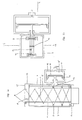
- FIGS. 1a and 1b show the front vertical section on the one hand, horizontal on the other hand, of an extendable telescopic support (1) in the picked up position, and its lateral thrust member (2).
- FIG. 2 represents a front vertical section of a support, in the extended position, with its system of articulated panels (3) (4) defining cross-pieces, articulated in the central part around axes (11) whose ends slide on one side on the vertical plate (3) shown here bordered by lateral flanges for retaining the rollers (8), disposed at the end of the piston rod (14) inside the male tubular body (6) and, on the opposite side, on the wall (7) facing it, by means of rollers (8), the rollers of the upper end faces (8 ′) being the only ones contact the inner wall (25) of the female element (12) of the telescopic device and ensuring the maintenance at the desired height.
- FIG. 3 represents a front vertical section of a support, in the extended position, with its system of articulated sections (5) (4) defining cross-pieces, articulated in the central part around axes (11) whose ends slide on one side on the vertical plate (3), shown here bordered by lateral flanges retaining the rollers (8) and flared (24) in its upper part disposed at the end of the "piston" rod (14) inside the body male tubular (6), and, on the opposite side, on the wall (7) which faces it, bevelled (24) in its upper part, by means of rollers (8), also in contact with the internal wall (25) of the female element (12) of the telescopic device, the rollers of the upper end faces (8 ′) while also ensuring the maintenance at the desired height.
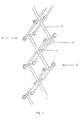
- FIG. 4 represents in perspective, the two alternations of articulated sections, respectively single (9) and double (10), each constituting half of the parallelograms which define a continuous series of cross-pieces and which, articulated first on an axis (11) at mid-length of the sections (5) (4), avoid the risk of sagging of the cross system.
- the mode of operation of the device according to the invention is mainly characterized by the greatest possible amplitude of its extension, the system of hinged hinges (5) (4) being able to penetrate the interior of the female part (12) of the extendable support, a stop (19), on the internal horizontal wall (25) of the female element (12) of the support, ensuring the limitation of its extension, and a stop / longitudinal guide (23), possibly constituting, to give it, as well as the support (1) as a whole, more rigidity, the female part of an internal telescopic device, sliding itself on a male part, integral with the part male (6) of the extendable support, this stop or this internal device laterally limiting the stroke of the axis / roller assembly (8 ′) disposed on the side of the plate (7) and possibly of the axes (11) during extension maximum, and thus avoiding a sag towards the central part of the sys cross bars (5) (4) in the extended position.
- the operating mode of the device is also characterized by the possibility for the system of cross-hinged panels (5) (4), to reintegrate its housing, during its contraction, in the male tubular body (6) of the device, thanks to, either to shorter articulated upper sections (20) devoid of rollers (8), or to the bevelled shape, both on the side (7) of the male tubular body and the vertical plate (3) facing it .
- the operating mode of the device is also characterized by the possibility of choosing the appropriate vertical position of the fulcrum (13) for the application, by the guided piston rod (14), of the lateral pressure of the air chamber ( 15) to the vertical plate (3) in the shape of a piston, taking into account the height of the stack of folded articulated sections remaining inside the guide zone (21) during maximum extension, and at this title necessarily provided with rollers (8) relative to the stack of upper articulated sections (20) caused to cross the height of the plate (3) during the maximum extension of the device.
- the mode of operation of the device is also characterized by the use of an air chamber (15) formed by the interior surface of the cylinder (16) and a membrane (17), which makes it possible to apply a constant pressure. at the "piston" head (18), in direct contact with the membrane, throughout its stroke, the latter being limited by a possible stop (22), integral with the "piston” head (18), the latter being spaced from the walls of the cylinder body (16) to allow the free deformation of the membrane (17).
- FIG. 5 represents an example of a device with double pneumatic control, actuating, in synchronism, two extendable support devices.
- the assembly shown comprises a tubular body of square or rectangular section (35), closed at its ends in the example shown, comprising a cylinder (40), inside which is defined an air chamber (36) actuating the two lateral membranes (17) and “pistons” (18), themselves triggering the movement of the articulated link device (43) which are connected to them through junction elements (37), as well as at least one central piston (38) with vertical movement, with return spring (44), and sliding in a guide (45).
- a second central piston can be provided opposite the first, symmetrically with respect to the horizontal axis defined by the air chamber (36) and the rods (14), which makes it possible, in this case, to balance the efforts at anchoring on rods, connecting rod support parts.
- Figure 5 also illustrates the mode of action of said links (43) by illustrating them in a first low position and a 2nd extreme position, shown in dotted lines, showing that the displacements are necessarily equal on both sides.
- FIG. 5 also represents a "piston" rod (14), and integral with the latter, a cam (31), which can exert an impulse on a sliding member (32), loaded by a spring (33), which member sliding comprises at its opposite end, a shoe (34) acting as brake of a caster (27), and which member, can be held in position relative to the caster support, either by a stop successively brought into projection, then cleared with respect to an upper range of said support, respectively during successive pulses, obtained by the cam or by manual means, such as a pedal or pivoting lever exerting a downward pulse on said sliding member, either by a cam said long, constantly depressing said sliding member.
- FIG. 5 also illustrates how the upper end of the supports (1) takes the form of a semi-cylindrical bearing (46), the axis of which is oriented parallel to the piston rods (14), this shape making it possible to retain a support constant linear of the frame or box spring, moving on said span.
- a semi-cylindrical bearing 46
- the axis of which is oriented parallel to the piston rods (14)
- two telescopic devices (1) can be associated to constitute a double support device, arranged in H, this arrangement bequeathing to the assembly the necessary rigidity, the pushing devices being arranged on each telescopic device (1) axis connecting to each other, so as to balance the offset action during the maximum extension of the parallelograms on the surfaces (25).
- the respective movements of two devices (1) thus associated can be synchronized by means of a device associating the operation of two air chambers or of the double air chamber, under the control of a single solenoid valve.
- the device according to the invention is particularly suitable for obtaining an inclination / inclination and or an elevation for beds used in hospitals, in medical communities, or in the context of hospitalization in home.
Landscapes
- Life Sciences & Earth Sciences (AREA)
- Engineering & Computer Science (AREA)
- Geology (AREA)
- Mechanical Engineering (AREA)
- Structural Engineering (AREA)
- Invalid Beds And Related Equipment (AREA)
Applications Claiming Priority (4)
| Application Number | Priority Date | Filing Date | Title |
|---|---|---|---|
| FR8712845 | 1987-09-17 | ||
| FR8712845A FR2620789A1 (fr) | 1987-09-17 | 1987-09-17 | Dispositif de support extensible a commande pneumatique |
| FR8800329 | 1988-01-14 | ||
| FR8800329A FR2626059A1 (fr) | 1988-01-14 | 1988-01-14 | Ensemble de support a hauteur variable a commande pneumatique centrale |
Publications (2)
| Publication Number | Publication Date |
|---|---|
| EP0308351A2 true EP0308351A2 (de) | 1989-03-22 |
| EP0308351A3 EP0308351A3 (de) | 1989-10-25 |
Family
ID=26226213
Family Applications (1)
| Application Number | Title | Priority Date | Filing Date |
|---|---|---|---|
| EP88402361A Withdrawn EP0308351A3 (de) | 1987-09-17 | 1988-09-19 | Längenveränderbare Strebe mit pneumatischer Steuerung, und Verwendung als Stütze, zum Beispiel für ein Krankenhausbett |
Country Status (1)
| Country | Link |
|---|---|
| EP (1) | EP0308351A3 (de) |
Cited By (4)
| Publication number | Priority date | Publication date | Assignee | Title |
|---|---|---|---|---|
| CN105472200A (zh) * | 2016-01-11 | 2016-04-06 | 摩多数据(深圳)有限公司 | 一种3d扫描仪智能伸缩控制系统 |
| CN111779945A (zh) * | 2020-06-14 | 2020-10-16 | 石门县张亮化家政服务有限公司 | 一种便于调节的视频会议拍摄装置 |
| CN112964512A (zh) * | 2021-02-20 | 2021-06-15 | 辽宁大学 | 一种便携式深水分层电动采水装置及其采水方法 |
| CN114162749A (zh) * | 2021-11-22 | 2022-03-11 | 桂林电子科技大学 | 一种自平衡送货机器人 |
Family Cites Families (4)
| Publication number | Priority date | Publication date | Assignee | Title |
|---|---|---|---|---|
| US2610824A (en) * | 1948-03-03 | 1952-09-16 | Henry G Stowe | Portable fluid operated lifting jack |
| FR2146098A1 (de) * | 1971-07-16 | 1973-03-02 | Dunlop Ltd | |
| FR2405209A1 (fr) * | 1977-10-06 | 1979-05-04 | Dunlop Sa | Appareil de levage |
| DE3418072A1 (de) * | 1984-05-16 | 1985-11-21 | Daniel Kollbrunn Küng | Vorrichtung zum vertikalen verstellen von betteilen und dgl. |
-
1988
- 1988-09-19 EP EP88402361A patent/EP0308351A3/de not_active Withdrawn
Cited By (4)
| Publication number | Priority date | Publication date | Assignee | Title |
|---|---|---|---|---|
| CN105472200A (zh) * | 2016-01-11 | 2016-04-06 | 摩多数据(深圳)有限公司 | 一种3d扫描仪智能伸缩控制系统 |
| CN111779945A (zh) * | 2020-06-14 | 2020-10-16 | 石门县张亮化家政服务有限公司 | 一种便于调节的视频会议拍摄装置 |
| CN112964512A (zh) * | 2021-02-20 | 2021-06-15 | 辽宁大学 | 一种便携式深水分层电动采水装置及其采水方法 |
| CN114162749A (zh) * | 2021-11-22 | 2022-03-11 | 桂林电子科技大学 | 一种自平衡送货机器人 |
Also Published As
| Publication number | Publication date |
|---|---|
| EP0308351A3 (de) | 1989-10-25 |
Similar Documents
| Publication | Publication Date | Title |
|---|---|---|
| EP0220968A1 (de) | Kontinuierlich arbeitende hydraulische Seilzugvorrichtung | |
| EP0308351A2 (de) | Längenveränderbare Strebe mit pneumatischer Steuerung, und Verwendung als Stütze, zum Beispiel für ein Krankenhausbett | |
| EP0365455B1 (de) | Transportvorrichtung für Patienten | |
| EP2210577B1 (de) | Bettrost | |
| EP3563002A1 (de) | Motorantriebsanordnung zur entfaltung einer zugkraft, verwendung der anordnung zum motorischen antrieb eines gelenkarms und zugehöriges verfahren | |
| FR2636717A2 (fr) | Dispositif de support extensible a commande pneumatique | |
| FR2679894A1 (fr) | Jambe de stabilisation formant pied d'appui pour une structure transportable telle qu'un abri technique par exemple. | |
| FR2620789A1 (fr) | Dispositif de support extensible a commande pneumatique | |
| FR2798053A1 (fr) | Dispositif pour soulever un sommier avec sa literie | |
| EP2589364B1 (de) | Orthopädisches Gerät zum Halten und Positionieren einer unteren Gliedmaße | |
| FR2868674A1 (fr) | Dispositif mecanique destine a elever une literie, pouvant s'arreter a toutes les positions comprises dans les limites et a l'interieur d'une course definie par un verin electromecanique | |
| FR2602655A1 (fr) | Dispositif de support d'un sommier de lit | |
| BE1026784B1 (fr) | Table elevatrice | |
| FR2679544A1 (fr) | Appareilage autonome permettant d'extraire et deplacer des elements encastres dans le sol, tels que plaques d'egouts, grilles. | |
| FR3006174A1 (fr) | Lit avec un sommier comprenant un releve buste | |
| FR2626059A1 (fr) | Ensemble de support a hauteur variable a commande pneumatique centrale | |
| CH501127A (fr) | Echafaudage | |
| FR2780639A1 (fr) | Lit de soins a elements telescopiques en forme de tiges | |
| FR2730147A1 (fr) | Lit ou articles similaires reglable en hauteur | |
| FR2483774A1 (fr) | Support de corps humain | |
| FR2822661A1 (fr) | Lit muni d'un releve-dos | |
| FR3039530A1 (fr) | Dispositif d'elevation | |
| FR2720243A1 (fr) | Structure de lit. | |
| EP0226682A1 (de) | Fahrgestell für den Krankentransport | |
| EP3780997B1 (de) | Einziehbarer sitz für hockposition |
Legal Events
| Date | Code | Title | Description |
|---|---|---|---|
| PUAI | Public reference made under article 153(3) epc to a published international application that has entered the european phase |
Free format text: ORIGINAL CODE: 0009012 |
|
| AK | Designated contracting states |
Kind code of ref document: A2 Designated state(s): DE FR GB |
|
| PUAL | Search report despatched |
Free format text: ORIGINAL CODE: 0009013 |
|
| AK | Designated contracting states |
Kind code of ref document: A3 Designated state(s): DE FR GB |
|
| STAA | Information on the status of an ep patent application or granted ep patent |
Free format text: STATUS: THE APPLICATION IS DEEMED TO BE WITHDRAWN |
|
| 18D | Application deemed to be withdrawn |
Effective date: 19900426 |