EP0308423B1 - Magnetische verbesserte motorsysteme mit veränderlicher reluktanz - Google Patents
Magnetische verbesserte motorsysteme mit veränderlicher reluktanz Download PDFInfo
- Publication number
- EP0308423B1 EP0308423B1 EP87903973A EP87903973A EP0308423B1 EP 0308423 B1 EP0308423 B1 EP 0308423B1 EP 87903973 A EP87903973 A EP 87903973A EP 87903973 A EP87903973 A EP 87903973A EP 0308423 B1 EP0308423 B1 EP 0308423B1
- Authority
- EP
- European Patent Office
- Prior art keywords
- stator
- teeth
- motor
- motor apparatus
- sections
- Prior art date
- Legal status (The legal status is an assumption and is not a legal conclusion. Google has not performed a legal analysis and makes no representation as to the accuracy of the status listed.)
- Expired
Links
Images


Classifications
-
- H—ELECTRICITY
- H02—GENERATION; CONVERSION OR DISTRIBUTION OF ELECTRIC POWER
- H02K—DYNAMO-ELECTRIC MACHINES
- H02K41/00—Propulsion systems in which a rigid body is moved along a path due to dynamo-electric interaction between the body and a magnetic field travelling along the path
- H02K41/02—Linear motors; Sectional motors
- H02K41/03—Synchronous motors; Motors moving step by step; Reluctance motors
- H02K41/031—Synchronous motors; Motors moving step by step; Reluctance motors of the permanent magnet type
- H02K41/033—Synchronous motors; Motors moving step by step; Reluctance motors of the permanent magnet type with armature and magnets on one member, the other member being a flux distributor
-
- H—ELECTRICITY
- H02—GENERATION; CONVERSION OR DISTRIBUTION OF ELECTRIC POWER
- H02K—DYNAMO-ELECTRIC MACHINES
- H02K21/00—Synchronous motors having permanent magnets; Synchronous generators having permanent magnets
- H02K21/38—Synchronous motors having permanent magnets; Synchronous generators having permanent magnets with rotating flux distributors, and armatures and magnets both stationary
- H02K21/44—Synchronous motors having permanent magnets; Synchronous generators having permanent magnets with rotating flux distributors, and armatures and magnets both stationary with armature windings wound upon the magnets
-
- H—ELECTRICITY
- H02—GENERATION; CONVERSION OR DISTRIBUTION OF ELECTRIC POWER
- H02K—DYNAMO-ELECTRIC MACHINES
- H02K37/00—Motors with rotor rotating step by step and without interrupter or commutator driven by the rotor, e.g. stepping motors
- H02K37/10—Motors with rotor rotating step by step and without interrupter or commutator driven by the rotor, e.g. stepping motors of permanent magnet type
- H02K37/20—Motors with rotor rotating step by step and without interrupter or commutator driven by the rotor, e.g. stepping motors of permanent magnet type with rotating flux distributors, the armatures and magnets both being stationary
Definitions
- the invention relates to variable reluctance electric motors and, particularly, to electric motors whose electrically-energized salient stator poles terminate in stator teeth that oppose rotor teeth on the rotor surface, and in which permanent magnets located between adjacent stator teeth and poled transverse to the stator-to-rotor gap enhance the motor torque relative to the applied excitation in ampere-turns.
- Such electric motors are disclosed in PCT International publication Document Number WO 85/05507).
- the enhancement disclosed in these application affords hybrid stepping motors and variable reluctance motors substantial increases, such as 50%, in torque constant.
- Permanent magnets of materials such as samarium cobalt between the stator teeth of hybrid stepping motors and between both the stator teeth and rotor teeth of variable reluctance motors. These magnets between stator teeth increase the utilization of the rotor's permanent magnet flux for a given ampere-turn excitation of the phase coils surrounding the stator poles.
- the "inter-teeth" magnets achieve this result by controlling the motor's working air gap and altering the permeance slope, i.e. the torque making mechanism.
- the inter-teeth magnets also increase the rate of change of flux through the teeth when the motor rotates, thereby improving the motor's performance as a generator.
- An object of the invention is to improve variable reluctance motors.
- Another object is to avoid the aforementioned disadvantages.
- Yet another object of the invention is to enhance the performance of variable reluctance motors while minimizing the inertia of the rotor.
- Another object is to enhance the performance in a cost-effective manner.
- such objects are attained, in whole or in part, by maintaining the polarity alignment of the inter-teeth permanent magnets transverse to the direction of rotor travel but reversing the polarity from pole to pole.
- the inter-teeth magnets are placed only between stator teeth.
- a driver drives the phase coils on the stator poles by energizing the coils on only half of the stator poles at one time.
- the driver energizes the coils unidirectionally.
- the coils of adjacent stator poles are wound in opposite directions.
- the driver drives oppositely wound coils on adjacent poles simultaneously during each step while leaving the next two poles unenergized.
- the driver energizes four phases in the step sequence 1 1 0 0 for the first step, 0 1 1 0 for the second step, 0 0 1 1 the third, 1 0 0 1 the fourth step, etc., where "1" represents energization and "0" non-energization.
- a driver DR receives control pulses from an external source (not shown) and drives a motor M.
- the driver also receives an external rotation direction signal which instructs the driver DR to rotate the motor in one or the other direction.
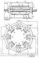
- the motor M appears in more detail in Figs. 2 and 3.
- a rotor 10 rotates within a stator 12 mounted within a housing schematically shown as 14.
- a shaft 16 projects through the housing 14 and is keyed to the rotor 10 for rotation therewith.
- Suitable bearings B not shown mount the rotor 10 and the shaft 16 to be rotatable within the housing 14.
- the rotor 10 is composed of annular laminations forming a hollow cylinder 18 secured to the shaft 16 by end caps 20.
- the rotor 10 about the outer periphery of the hollow cylinder 18, carries fifty peripherally spaced teeth 36 projecting radially outward.
- the number of teeth shown is only an example.
- Other embodiments of the invention utilize rotors with other numbers of teeth such as 40 or 48.
- the angular or peripheral tooth pitch that is, the angular distance between like points on adjacent rotor teeth 36 is 7.2 degrees.
- the teeth 36 are spaced about the entire periphery of the rotor 10. Each tooth extends longitudinally along the axial direction of the rotor from one rotor end to the other.
- poles 40, 42, 44, 46, 48, 50, 52, and 54 project inwardly from a common circumscribing stator portion 56 to form the stator 12.
- the poles extend longitudinally along the entire axial dimension of the stator 12 beyond the rotor 10.
- Five stator pole teeth or stator teeth 58 form the inner radial ends of each pole 40 to 54.
- the pole teeth 58 are formed along an imaginary cylindrical surface coaxial with the rotor 10 and spaced slightly from the rotor teeth 36 and 38 across an air gap 59 .
- the pole teeth are pitched at 7.2 degrees. Thus, here they have the same pitch as the rotor teeth 36 and 38.
- the poles 40 to 54 and their respective teeth 58 are angularly positioned so that the teeth on two opposite poles such as 40 and 48 can directly oppose the rotor teeth 36 when teeth on poles 44 and 52 ninety degrees therefrom are completely out of alignment with the teeth 36.
- the teeth 58 on the remaining forty-five degree angularly oriented poles 42, 46, 50, and 54 are angularly arranged so that they are ninety degrees and 270 degrees out of phase with the angular alignment of the rotor teeth 36, in the same rotor position.
- Stator coils 60 magnetize the poles 40 to 54 in a sequence that causes rotation of the rotor 10. Details of the stator coils 60 and their arrangement on the stator appear schematically in Fig. 4. Here the eight coils are formed of eight respective windings 82, 84, 86, 88, 90, 92, 94, and 96.
- the winding 82 is connected in series with the winding 90
- the winding 86 is in series with the winding 94
- the winding 88 in series with the winding 96.
- the series windings 82 and 90 are energized by phase A of the driver DR, the series windings 84 and 92 by phase B, the series windings 86 and 94 by phase C, and the series windings 88 and 96 by phase D.
- each two windings represent one of four phases A, B, C, and D.
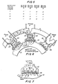
- the valleys between the stator teeth are filled with a high magnetic coercivity material 110 and 120 such as samarium cobalt.
- a high magnetic coercivity material 110 and 120 such as samarium cobalt.
- any magnetic rare earth cobalt or neodymiumboron iron alloys or Ferrites or Alnicos are used. Included among the known magnetic rare earth materials are Nd and Sm.
- the magnetic materials 110 and 120 constitute shaped magnets.
- the magnetic material 110 between the teeth of alternate poles 40, 44, 48, and 52 is radially poled in one direction, and the magnetic material 120 between the teeth of adjacent alternate poles 42, 46, 50 and 54 is radially poled in the opposite direction. That is, the spaces between the stator teeth 58 of adjacent poles have oppositely poled magnetic materials 110 and 120.
- Fig. 5 illustrates the phase sequence or energization sequence of the windings or coils 82, 84, 86, 88, 90, 92, 94, and 96. Details of two adjacent poles, winding directions, magnets, and fluxes appear in Fig. 6, with the motor at a stable equilibrium position and with one pole of each phase on.
- the driver DR generates unidirectional current pulses and the winding directions of windings 82 to 96 are set always to aid the transformer coupling effect from pole to pole.
- the direction in which the magnetic materials 110 and 120 are poled always opposes the magnetic polarity which the windings 82 to 96 induce in the poles 40 to 54 in which they are mounted.
- the windings 82 to 96 are wound to induce polarities which oppose the polarities of the magnetic materials 110 and 120. That is when the windings 82, 86, 90, or 94 induce magnetic fields in the poles 40, 44, 48, or 52, the polarities of the poles are North and South radially inward.
- the magnetic materials 110 in these poles exhibit polarities South to North radially inward.
- the windings 84, 88, 92, or 96 energize poles 42, 46, 50, or 54, the resulting polarities of the poles are South to North radially inward.
- the polarities of the magnetic materials 120 oppose these polarities by being North to South radially inward.
- the magnetic materials 110 and 120 interact with the flux induced in the poles by redirecting the leakage flux into the teeth.
- the driving sequence or phase sequence of the driver DR is such as to energize only four of the eight poles at any time. That is, at any time, two adjacent poles such as 40 and 42 are energized to be magnetized in opposite directions, the next two such as 44 and 46 are un-energized, the next two such as 48 and 50 energized for magnetization in opposite directions, and the last two such as 52 and 54 are unenergized.
- the driver DR de-energizes the first of each two previously-energized poles such as 40 and 48 and energizes the first of each two previously unenergized poles such as 44 and 52. In succeeding steps, that pattern is repeated as shown in Fig. 5.
- the driver DR applies voltage pulses to the windings 82 to 96 in four phases A to D during any one step and continues in sequential steps. That is, the driver produces four parallel simultaneous excitations each of which is on or off, i. e. "0" or "1". Specifically, the driver DR pulses windings 82 and 90 (phase A), windings 84 and 92 (phase B), 86 and 94 (phase C), and windings 88 and 96 (phase D), i.e.
- Stepping the variable reluctance motor turns the rotor 10 because each step of field winding excitation constrains the rotor to seek a position that forms a magnetic path of least reluctance through the air gap 59 and rotor teeth 36 and stator teeth 58.
- Each change in working air gap permeance provided by the rotor teeth 36 and stator teeth 58 produces torque.
- a step If a step lasts long enough, the rotor reaches the stable equilibrium position it seeks during the step. Such a position is shown in Fig. 6.
- stator pole 40 phase A
- stator pole 54 draws the rotor teeth 36 to the right or clockwise.
- pole 48 helps pole 40 draw the rotor counterclockwise and pole 46 aids pole 54 in the clockwise pull.
- the succeeding step de-energizes pole 54 (and pole 46) and energizes adjacent pole 42 (and pole 50) which helps pole 40 (and pole 48 ) draw the rotor teeth 36 counterclockwise to the left toward another equilibrium position where the pole 40 is de-energized.
- the pole 44 (and pole 52) helps pole 42 and pole 50 draw the rotor counterclockwise another step. The process continues as long as the driver DR steps the motor M.
- the motor system furnishes a substantial improvement in variable reluctance motors by furnishing significantly higher torques for the same number of ampere-turns compared to prior motors, or by furnishing the same torque with fewer ampere-turns than previous variable reluctance motors.
- the motor system also provides improved torque when compared to comparably sized and energized magnetically enhanced hybrid motors.
- the invention may also be practiced by turning the windings 82 to 96 in the same direction and having the driver DR drive the windings 84, 88, 92, and 96 in directions opposite to the windings 82, 86, 90, and 94.
- FIG. 8 Another embodiment of the invention is shown in Fig. 8.
- the invention is practiced with a linear motor where a stator 150 is actuated in the same manner as in the rotating motor M to drive an actuator 152.
- FIG. 9 Another embodiment of the invention is shown in Fig. 9 where the permanent magnets 162 and 164 are embedded in poles 158 and 160 to form teeth 166 between them. Successive poles have magnets 162 and 164 alternately embedded therein so each pole corresponds either to pole 158 or 160.
- FIG. 10 and 11 Another embodiment of the invention is shown in Figs. 10 and 11.
- the poles 40 to 54 carry windings 140 to 154 all wound in the same direction and connected in series to form four phases as shown.
- the driver DR excites the windings on a bipolar basis. That is the driver passes current in one or the other direction, indicated by "1" or "-1", in each phase and also turns the windings off as indicated by "0".
- the phases and steps used appear in Fig. 11. As can be seen adjacent energized phases are excited in opposite directions to achieve opposite polarities which oppose the polarities of the magnetic materials 110 and 120.
- the motor according to the invention furnishes the ability to increase torque for corresponding excitation in ampere turns not only with respect to corresponding variable reluctance motors, magnetically enhanced variable reluctance motors, and hybrid motors, but also enhanced hybrid motors.
Landscapes
- Engineering & Computer Science (AREA)
- Power Engineering (AREA)
- Physics & Mathematics (AREA)
- Chemical & Material Sciences (AREA)
- Combustion & Propulsion (AREA)
- Electromagnetism (AREA)
- Linear Motors (AREA)
- Control Of Stepping Motors (AREA)
- Reciprocating, Oscillating Or Vibrating Motors (AREA)
- Permanent Magnet Type Synchronous Machine (AREA)
- Iron Core Of Rotating Electric Machines (AREA)
- Synchronous Machinery (AREA)
Claims (17)
- Motorvorrichtung, umfassend:(a) einen Stator (12);(b) eine Vielzahl von Statorpolen (40, 42, 44, 46, 48, 50, 52, 54) am genannten Stator;(c) eine Windung (60) auf jedem der genannten Statorpole;(d) eine Vielzahl von im Abstand zueinander angeordneten Statorzähnen (58) auf den genannten Statorpolen, wobei jeder der genannten Statorpole zumindest einen Zahn aufweist;(e) eine Bewegungsvorrichtung (10), die bezüglich des genannten Stators beweglich ist;(f) wobei die genannte Bewegungsvorrichtung eine Vielzahl von im Abstand zueinander angeordneten Bewegungsvorrichtungzähnen (36) aufweist, die zur Bewegung entlang einer ersten Richtung vorbei an den genannten Statorzähnen angeordnet sind;
gekennzeichnet durch(g) eine Vielzahl von Abschnitten (110, 120) aus Permanentmagnetmaterial auf den genannten Statorpolen, wobei jeder der genannten Abschnitte zu einem Statorzahn benachbart angeordnet und in eine zur ersten Richtung quergerichtete Richtung gepolt ist; und(h) dadurch, daß die Abschnitte (110) auf jedem der genannten Statorpole quer zur ersten Richtung aber entgegengesetzt zur Polungsrichtung der Abschnitte (120) an benachbarten Statorpolen gepolt sind. - Motorvorrichtung nach Anspruch 1, dadurch gekennzeichnet, daß jeder der genannten Statorpole (40, 42, 44, 46, 48, 50 ,52, 54) eine Vielzahl von Zähnen (58) und Abschnitte zwischen benachbarten Zähnen umfaßt.
- Motorvorrichtung nach Anspruch 1 oder 2, dadurch gekennzeichnet, daß die genannte Bewegungsvorrichtung ein Rotor ist.
- Motorvorrichtung nach einem der Ansprüche 1 bis 3, dadurch gekennzeichnet, daß das genannte Permanentmagnetmatrial Samariumkobalt ist.
- Motorvorrichtung nach einem ader Ansprüche 1 bis 3, dadurch gekennzeichnet, daß das genannte Permanentmagnetmaterial eine Neodymborlegierung ist.
- Motorvorrichtung nach einem der Ansprüche 1 bis 5, dadurch gekennzeichnet, daß die genannten Abschnitte Permanentmagneteinsätze sind.
- Motorvorrichtung nach einem der Ansprüche 1 bis 6, dadurch gekennzeichnet, daß die Windungen (60) an benachbarten Statorpolen in entgegengesetzten Richtungen gewunden sind, sodaß die Polarität eines jeden Statorpols (40, 44, 48, 52) der Polarität des benachbarten Statorpols (42, 46, 50, 54) entgegengesetzt wird, wenn jede der genannten Windungen durch Strom in der gleichen Richtung erregt wird, und entgegengesetzt zur Polarität der genannten Abschnitte (110, 120).
- Motorvorrichtung nach einem der Ansprüche 1 bis 7, dadurch gekennzeichnet, daß jeder der genannten Statorpole eine Vielzahl von Zähnen und Abschnitten zwischen benachbarten Zähnen umfaßt.
- Motorvorrichtung nach einem der Ansprüche 1 bis 8, dadurch gekennzeichnet, daß die genannten Statorpole Oberflächen aufweisen, die dem Rotor zugewandt sind, und die genannten Statorzähne dadurch gebildet werden, daß die Abschnitte unterhalb der Oberflächen angeordnet und die Abschnitte im Abstand zueinander angeordnet werden, sodaß Zähne zwischen ihnen gebildet werden.
- Motorvorrichtung nach einem der Ansprüche 1 bis 6, dadurch gekennzeichnet, daß der genannte Stator und die genannte Bewegungsvorrichtung einen Motor (M) bilden und eine Treibereinrichtung zum Erzeugen einer Impulsspannung, wenn die Windungen den Motor in Gang setzen.
- Motorvorrichtung nach Anspruch 10, dadurch gekennzeichnet, daß die genannte Treibereinrichtung (DR) so angeordnet ist, daß sie vier Phasen von kodierten Impulsen erzeugt, um die Windungen (60) an den Statorpolen dazu zu veranlassen, Polaritäten in der gleichen Richtung wie jeder der genannten Abschnitte (110, 120) auf jedem der genannten Statorpole zu erzeugen.
- Motorvorrichtung nach Anspruch 10, dadurch gekennzeichnet, daß die Windungen (60) an benachbarten Statorpolen (40, 42, 44, 46, 48, 50, 52, 54) in entgegengesetzten Richtungen gewunden sind, sodaß die Polarität eines jeden Statorpols (40, 44, 48, 52) der Polarität der benachbarten Statorpole (42, 46, 50, 54) entgegengesetzt wird, wenn jede der genannten Windungen durch Strom in der gleichen Richtung erregt wird, und entgegengesetzt zur Polarität der genannten Abschnitte (110, 120).
- Motorvorrichtung nach einem der Ansprüche 10 bis 12, dadurch gekennzeichnet, daß die genannte Treibereinrichtung (DR) so angeordnet ist, daß die Impulse in einer Richtung erzeugt werden.
- Motorvorrichtung nach einem der Ansprüche 10 bis 12, dadurch gekennzeichnet, daß die genannte Treibereinrichtung so angeordnet ist, daß die Impulse in einer Richtung in vier Phasen A, B, C und D in Schritten solcherart erzeugt werden, daß für die jeweiligen Phasen A, B, C und D die Impulse 1 1 0 0 für einen ersten Schritt, 0 1 1 0 für einen zweiten Schritt, 0 0 1 1 für einen dritten Schritt und 1 0 0 1 für einen vierten Schritt sind.
- Motorvorrichtung nach einem der Ansprüche 1 bis 14, dadurch gekennzeichnet, daß der genannte Motor (M) ein Rotationsmotor ist.
- Motovorrichtung nach einem der Ansprüche 10 bis 14, dadurch gekennzeichnet, daß der genannte Motor (M) ein Linearmotor ist.
- Motorvorrichtung nach einem der Ansprüche 10, 11, 12, 13, 15 und 16, dadurch gekennzeichnet, daß die genannte Treibereinrichtung so angeordnet ist, daß eine Vielzahl von Schritten mit vier Phasen pro Schritt erzeugt wird, wobei die genannten Phasen 1 1 0 0 für den ersten Schritt und 0 1 1 0, 0 0 1 1 und 1 0 0 1 für die darauffolgenden Schritte sind, wobei "0" ein Zustand mit abgeschaltetem Strom und "1" ein Zustand mit eingeschaltetem Strom ist.
Priority Applications (1)
| Application Number | Priority Date | Filing Date | Title |
|---|---|---|---|
| AT87903973T ATE79987T1 (de) | 1986-06-04 | 1987-06-04 | Magnetische verbesserte motorsysteme mit veraenderlicher reluktanz. |
Applications Claiming Priority (2)
| Application Number | Priority Date | Filing Date | Title |
|---|---|---|---|
| US870625 | 1986-06-04 | ||
| US06/870,625 US4713570A (en) | 1986-06-04 | 1986-06-04 | Magnetically enhanced variable reluctance motor systems |
Publications (3)
| Publication Number | Publication Date |
|---|---|
| EP0308423A1 EP0308423A1 (de) | 1989-03-29 |
| EP0308423A4 EP0308423A4 (de) | 1989-03-29 |
| EP0308423B1 true EP0308423B1 (de) | 1992-08-26 |
Family
ID=25355807
Family Applications (1)
| Application Number | Title | Priority Date | Filing Date |
|---|---|---|---|
| EP87903973A Expired EP0308423B1 (de) | 1986-06-04 | 1987-06-04 | Magnetische verbesserte motorsysteme mit veränderlicher reluktanz |
Country Status (6)
| Country | Link |
|---|---|
| US (1) | US4713570A (de) |
| EP (1) | EP0308423B1 (de) |
| JP (1) | JP2549538B2 (de) |
| AT (1) | ATE79987T1 (de) |
| DE (1) | DE3781410T2 (de) |
| WO (1) | WO1987007784A1 (de) |
Families Citing this family (53)
| Publication number | Priority date | Publication date | Assignee | Title |
|---|---|---|---|---|
| US5010262A (en) * | 1988-07-20 | 1991-04-23 | Shinko Electric Company Ltd. | Strong magnetic thrust force type actuator |
| US4883999A (en) * | 1988-08-15 | 1989-11-28 | Pacific Scientific Company | Polyphase electronically commutated reluctance motor |
| EP0373987B1 (de) * | 1988-11-22 | 1993-11-10 | Shinko Electric Co. Ltd. | Betätigungsgerät mit starker magnetischer Schiebekraft |
| JPH02292583A (ja) * | 1989-02-17 | 1990-12-04 | Yaskawa Electric Mfg Co Ltd | 電動制御弁 |
| JPH083191Y2 (ja) * | 1989-02-17 | 1996-01-29 | 株式会社安川電機 | キャンドモータ |
| US4922604A (en) * | 1989-03-13 | 1990-05-08 | Pacific Scientific Company | Method of fabricating an encapsulated motor |
| US5008572A (en) * | 1989-03-13 | 1991-04-16 | Pacific Scientific Company | Encapsulated motor with precision bearing registration |
| US5023546A (en) * | 1989-11-08 | 1991-06-11 | General Motors Corporation | Variable reluctance rotation sensor with changing coil linkages and a pair of flux producing magnets |
| US5023547A (en) * | 1989-11-08 | 1991-06-11 | General Motors Corporation | Variable reluctance rotation sensor with changing flux linkages and including a pair of oppositely poled magnets |
| US5327069A (en) * | 1992-06-19 | 1994-07-05 | General Electric Company | Switched reluctance machine including permanent magnet stator poles |
| JP3388275B2 (ja) * | 1993-02-01 | 2003-03-17 | ミネベア株式会社 | 多相ハイブリッド型ステッピングモータの駆動方法 |
| US5773908A (en) * | 1993-02-22 | 1998-06-30 | General Electric Company | Single phase motor with positive torque parking positions |
| USRE37576E1 (en) * | 1993-02-22 | 2002-03-12 | General Electric Company | Single phase motor with positive torque parking positions |
| US5504424A (en) * | 1993-05-28 | 1996-04-02 | Durakool, Inc. | Variable reluctance sensor utilizing a magnetic bobbin |
| US5806169A (en) * | 1995-04-03 | 1998-09-15 | Trago; Bradley A. | Method of fabricating an injected molded motor assembly |
| US5726560A (en) * | 1995-09-01 | 1998-03-10 | Barber-Colman Company | Switched reluctance generator |
| US5886442A (en) * | 1995-09-26 | 1999-03-23 | Ogino; Sanshiro | Magnetic attraction driving engine using permanent magnet |
| JPH1023732A (ja) * | 1996-07-05 | 1998-01-23 | Tamagawa Seiki Co Ltd | ハイブリッド型ステップモータ |
| TW410354B (en) | 1998-01-27 | 2000-11-01 | Genesis Kk | Hybrid-type magnet and stepping motor including same |
| BR9804426A (pt) * | 1998-10-16 | 2000-05-16 | Elevadores Atlas S A | Máquina elétrica de relutância subsìncrona. |
| AU2001289294A1 (en) | 2000-03-30 | 2001-10-15 | Delware Capital formation | Variable reluctance motor with improved tooth geometry |
| US20030038556A1 (en) * | 2000-03-30 | 2003-02-27 | Gieskes Koenraad Alexander | Variable reluctance motor |
| KR100442122B1 (ko) * | 2001-07-31 | 2004-07-30 | 한국전기연구원 | 영구 자석을 이용한 브러시리스 발전기 |
| US6724114B2 (en) * | 2001-12-28 | 2004-04-20 | Emerson Electric Co. | Doubly salient machine with angled permanent magnets in stator teeth |
| US6777842B2 (en) | 2001-12-28 | 2004-08-17 | Emerson Electric Co. | Doubly salient machine with permanent magnets in stator teeth |
| US6965183B2 (en) | 2003-05-27 | 2005-11-15 | Pratt & Whitney Canada Corp. | Architecture for electric machine |
| US7545056B2 (en) * | 2003-05-27 | 2009-06-09 | Pratt & Whitney Canada Corp. | Saturation control of electric machine |
| US7583063B2 (en) | 2003-05-27 | 2009-09-01 | Pratt & Whitney Canada Corp. | Architecture for electric machine |
| US7262539B2 (en) | 2004-11-26 | 2007-08-28 | Pratt & Whitney Canada Corp. | Saturation control of electric machine |
| BRPI0402045B1 (pt) * | 2004-05-12 | 2021-04-13 | Oscar Rolando Avilla Cusicanqui | Motor elétrico híbrido de relutância |
| KR100600758B1 (ko) * | 2004-09-15 | 2006-07-19 | 엘지전자 주식회사 | 모터의 스테이터 및 그 제조방법 |
| DE102005045348A1 (de) * | 2005-09-22 | 2007-04-05 | Siemens Ag | Zahnmodul für ein permanentmagneterregtes Primärteil einer elektrischen Maschine |
| DE102006005046A1 (de) * | 2006-02-03 | 2007-08-09 | Siemens Ag | Elektrische Maschine mit ungleichmäßigen Polzähnen |
| US7288923B1 (en) | 2006-04-21 | 2007-10-30 | Pratt & Whitney Canada Corp. | Voltage-limited electric machine |
| US20080030108A1 (en) * | 2006-08-07 | 2008-02-07 | Kollmorgen Corporation | Hybrid stepper motor having magnetic enhancement and heat dissipating housing |
| EP1919063A1 (de) * | 2006-11-02 | 2008-05-07 | Sy.Tra.Ma. S.R.L. | Flussumkehr-Linearmotor |
| DE102007005131B3 (de) * | 2007-02-01 | 2008-01-31 | Siemens Ag | Ringmotor |
| EP2012414B1 (de) * | 2007-07-05 | 2020-03-25 | Korea Electrotechnology Research Institute | Geräuscharmer, Hochgeschwindigkeits-, Hochpräzisions- und Hochleistungs-Flussumkehrmotor für ein Linear- und Drehbewegungssystem |
| GB2454171B (en) * | 2007-10-29 | 2012-05-23 | Technelec Ltd | Reluctance machines with permanent magnets integrated into the stator |
| GB2457682B (en) * | 2008-02-21 | 2012-03-28 | Magnomatics Ltd | Variable magnetic gears |
| CN102160267B (zh) * | 2008-08-29 | 2013-08-21 | 莫戈公司 | 永磁型步进电动机 |
| KR101065613B1 (ko) * | 2009-04-13 | 2011-09-20 | 한국전기연구원 | 선형 및 회전형 전기기기 구조 |
| EP2345141B1 (de) * | 2009-09-08 | 2019-03-06 | Moog Inc. | Schrittmotor, der kleine inkremente erzeugen kann |
| NO332245B1 (no) * | 2011-02-03 | 2012-08-06 | Greenway As | Asymmetrisk multitannet reluktansmotor med seks koiler |
| CN102158042B (zh) * | 2011-03-25 | 2012-12-05 | 哈尔滨工业大学 | 高动态圆筒形直线磁阻电机 |
| RU2526846C2 (ru) * | 2012-06-09 | 2014-08-27 | Федеральное государственное автономное образовательное учреждение высшего профессионального образования "Уральский федеральный университет имени первого Президента России Б.Н. Ельцина" | Бесщеточная электрическая машина |
| CN105305671B (zh) * | 2015-10-22 | 2018-06-26 | 南京航空航天大学 | 一种圆筒型动铁式永磁直线发电机 |
| CN106981968A (zh) * | 2017-05-03 | 2017-07-25 | 南京航空航天大学 | 独立绕组连续极双边平板型永磁直线电机 |
| US10742078B2 (en) | 2017-10-26 | 2020-08-11 | Hamilton Sunstrand Corporation | Variable torque electric motor assembly |
| CN109672276B (zh) * | 2018-12-21 | 2021-01-15 | 南京航空航天大学 | 一种交替极永磁偏置无轴承双凸极电机及其控制方法 |
| US11456653B2 (en) * | 2019-03-28 | 2022-09-27 | Ghsp, Inc. | Hybrid stepper motor utilizing axial coils for adjusting the magnetic field of the rotor |
| CN110690806B (zh) * | 2019-08-19 | 2021-09-24 | 中国矿业大学 | 一种平板型初级永磁式横向磁通直线电机 |
| US20240235286A1 (en) * | 2022-03-16 | 2024-07-11 | Jiangsu University | Single winding hybrid excitation magnetic field modulation motor and synergy excitation design method thereof |
Family Cites Families (45)
| Publication number | Priority date | Publication date | Assignee | Title |
|---|---|---|---|---|
| US2993134A (en) * | 1957-01-02 | 1961-07-18 | Gen Electric | Permanent magnet motor |
| US3215875A (en) * | 1962-09-27 | 1965-11-02 | Controls Co Of America | Dynamoelectric machine |
| FR94950E (fr) * | 1964-09-30 | 1970-01-23 | Georges Stcherbatcheff | Moteur électrique a circuit magnétique en pont. |
| US3310697A (en) * | 1964-11-18 | 1967-03-21 | Oak Electro Netics Corp | Self-starting synchronous motor |
| US3334254A (en) * | 1965-06-03 | 1967-08-01 | Garrett Corp | Dynamoelectric machine |
| US3439200A (en) * | 1966-01-18 | 1969-04-15 | Yokogawa Electric Works Ltd | Reversible stepping motor with braking coils and biasing permanent magnets |
| US3566251A (en) * | 1968-05-06 | 1971-02-23 | Westinghouse Electric Corp | Series field for permanent magnet machine |
| DE1763876A1 (de) * | 1968-08-28 | 1972-02-03 | Siemens Ag | Permanenterregte elektrische Maschine |
| US3500081A (en) * | 1968-11-26 | 1970-03-10 | Ibm | Low inertia stepping motor |
| US3495107A (en) * | 1969-04-28 | 1970-02-10 | Tri Tech | Cylindrical stepper motor having a stator biasing magnet |
| US3671841A (en) * | 1970-05-01 | 1972-06-20 | Tri Tech | Stepper motor with stator biasing magnets |
| FR2131979B1 (de) * | 1971-02-26 | 1976-07-23 | Seiko Instr & Electronics | |
| US3906268A (en) * | 1971-05-28 | 1975-09-16 | Kollmorgen Photocircuits | High density flux magnetic circuit |
| US3750151A (en) * | 1971-08-25 | 1973-07-31 | H Dill | Three-phase rotating ring display |
| FR2211791B1 (de) * | 1972-12-21 | 1977-08-12 | Akad Wissenschaften Ddr | |
| US3979616A (en) * | 1973-02-19 | 1976-09-07 | Kienzle Uhrenfabriken Gmbh | Unipolar rotary step motor |
| FR2232125A1 (de) * | 1973-06-01 | 1974-12-27 | Suwa Seikosha Kk | |
| US3836802A (en) * | 1973-09-06 | 1974-09-17 | Gen Electric | Permanent magnet motor |
| FR2259472A1 (en) * | 1974-01-30 | 1975-08-22 | Valroger Pierre | Polyphase linear motor for high-speed traction - has field coils fed with polyphase current controlled by thyristors |
| US4048531A (en) * | 1974-06-05 | 1977-09-13 | The Singer Company | Variable reluctance stepper motor |
| DE2429492C3 (de) * | 1974-06-20 | 1979-04-26 | Elmeg-Elektro-Mechanik Gmbh, 3150 Peine | Schrittweise oder kontinuierlich betreibbarer elektrischer Motor, insbesondere Schrittmotor zum Antrieb eines Rollenzählwerkes |
| DE2460630B2 (de) * | 1974-12-20 | 1976-09-30 | Siemens AG, 1000 Berlin und 8000 München | Dauermagneterregte gleichstrommaschine |
| US3984711A (en) * | 1975-04-07 | 1976-10-05 | Warner Electric Brake & Clutch Company | Variable reluctance step motor with permanent magnets |
| US4190779A (en) * | 1976-05-04 | 1980-02-26 | Ernest Schaeffer | Step motors |
| US4075518A (en) * | 1976-06-22 | 1978-02-21 | Bulova Watch Company, Inc. | Micro-miniature stepping motor |
| JPS5367015U (de) * | 1976-11-10 | 1978-06-06 | ||
| US4112319A (en) * | 1976-12-23 | 1978-09-05 | Sigma Instruments, Inc. | Synchronous motor with heterogeneously pitched teeth |
| DE2707251A1 (de) * | 1977-02-19 | 1978-08-24 | Quarz Zeit Ag | Einphasenschrittmotor |
| FR2386179A1 (fr) * | 1977-03-28 | 1978-10-27 | Kollmorgen Tech Corp | Machines electriques tournantes perfectionnees |
| US4127802A (en) * | 1977-04-06 | 1978-11-28 | Johnson Milton H | High torque stepping motor |
| US4315171A (en) * | 1977-05-23 | 1982-02-09 | Ernest Schaeffer | Step motors |
| US4371799A (en) * | 1977-10-25 | 1983-02-01 | General Electric Company | Permanent magnet field pole for a direct current dynamoelectric machine |
| JPS5484207A (en) * | 1977-12-19 | 1979-07-05 | Oki Electric Ind Co Ltd | Pulse motor |
| US4286180A (en) * | 1978-07-20 | 1981-08-25 | Kollmorgen Technologies Corporation | Variable reluctance stepper motor |
| DE2912688A1 (de) * | 1978-08-11 | 1980-02-14 | Copal Electronics | Schrittmotor |
| US4207483A (en) * | 1978-09-01 | 1980-06-10 | Warner Electric Brake & Clutch Co. | Step motor with circumferential stators on opposite sides of disc-like rotor |
| JPS5725151A (en) * | 1980-07-22 | 1982-02-09 | Matsushita Electric Ind Co Ltd | Linear motor |
| US4339679A (en) * | 1981-01-16 | 1982-07-13 | Litton Systems, Inc. | Low-inertia high-torque synchronous induction motor |
| US4424463A (en) * | 1981-05-27 | 1984-01-03 | Musil J Donald | Apparatus for minimizing magnetic cogging in an electrical machine |
| JPS5986466A (ja) * | 1982-11-09 | 1984-05-18 | Yaskawa Electric Mfg Co Ltd | 永久磁石界磁同期機 |
| JPS59153457A (ja) * | 1983-02-18 | 1984-09-01 | Sanyo Denki Kk | ハイブリツド形リニアステツピングモ−タ |
| DE3335626A1 (de) * | 1983-09-30 | 1985-04-11 | Siemens AG, 1000 Berlin und 8000 München | Homopolar erregte ein- oder mehrphasige wechselstrommaschine |
| FR2563059B1 (fr) * | 1984-04-13 | 1988-04-15 | Cem Comp Electro Mec | Machine electrodynamique vernier |
| KR930001777B1 (ko) * | 1984-05-21 | 1993-03-13 | 시그마 인스트루먼트스 인코포레이티드 | 스텝핑 모우터 |
| JPS62185552A (ja) * | 1986-02-10 | 1987-08-13 | Tokyo Electric Co Ltd | 複合型ステツピングモ−タ |
-
1986
- 1986-06-04 US US06/870,625 patent/US4713570A/en not_active Expired - Lifetime
-
1987
- 1987-06-04 EP EP87903973A patent/EP0308423B1/de not_active Expired
- 1987-06-04 WO PCT/US1987/001310 patent/WO1987007784A1/en not_active Ceased
- 1987-06-04 AT AT87903973T patent/ATE79987T1/de active
- 1987-06-04 DE DE8787903973T patent/DE3781410T2/de not_active Expired - Lifetime
- 1987-06-04 JP JP62503642A patent/JP2549538B2/ja not_active Expired - Lifetime
Also Published As
| Publication number | Publication date |
|---|---|
| EP0308423A1 (de) | 1989-03-29 |
| EP0308423A4 (de) | 1989-03-29 |
| JP2549538B2 (ja) | 1996-10-30 |
| JPH02503381A (ja) | 1990-10-11 |
| DE3781410D1 (de) | 1992-10-01 |
| ATE79987T1 (de) | 1992-09-15 |
| US4713570A (en) | 1987-12-15 |
| DE3781410T2 (de) | 1992-12-03 |
| WO1987007784A1 (en) | 1987-12-17 |
Similar Documents
| Publication | Publication Date | Title |
|---|---|---|
| EP0308423B1 (de) | Magnetische verbesserte motorsysteme mit veränderlicher reluktanz | |
| US4712028A (en) | Magnetically assisted stepping motor | |
| US4763034A (en) | Magnetically enhanced stepping motor | |
| US2968755A (en) | Magnetic motor | |
| US7432623B2 (en) | Brushless electromechanical machine | |
| EP0031026B1 (de) | Bürstenloser Gleichstrommotor | |
| US6320347B1 (en) | Method of driving directly a rotary drum in a reproducing machine by a prime mover | |
| US4728830A (en) | Electric motor with magnetic enhancement | |
| EP0349056A1 (de) | Elektrische Mehrpolmaschine | |
| US5117128A (en) | Motor with both stepped rotary and axial shift motions | |
| US3059131A (en) | Synchronous motors | |
| US4792709A (en) | Winding for operation of a three-phase stepping motor from a two-phase drive | |
| EP0183792B1 (de) | Schrittmotor mit magnetischer verstärkung | |
| US3506859A (en) | Electric stepping motor with plural field windings and energizing circuitry | |
| EP1550197B1 (de) | Verfahren und vorrichtung zur verwendung der statorwicklung eines elektrischen motors zur magnetisierung von dauermagneten des laüfers, wenn die statorwicklungsbreite kleiner als die weite jedes dauermagnetpols ist | |
| US4755703A (en) | Electric motor | |
| US4933585A (en) | High performance electric machine resistant to losses caused by the joule effect | |
| JP4061835B2 (ja) | 電動機 | |
| US4488069A (en) | Stepping motor | |
| EP0348984A1 (de) | Binärer bürstenloser Alternator und Motor | |
| JP2796233B2 (ja) | 動力発生装置 | |
| JP3228782U (ja) | 永久磁石を用いたモータ | |
| SU1365276A1 (ru) | Однофазный шаговый электродвигатель | |
| JPS5656163A (en) | Brushless motor | |
| JPH0636666B2 (ja) | ステツピングモ−タ |
Legal Events
| Date | Code | Title | Description |
|---|---|---|---|
| PUAI | Public reference made under article 153(3) epc to a published international application that has entered the european phase |
Free format text: ORIGINAL CODE: 0009012 |
|
| 17P | Request for examination filed |
Effective date: 19881129 |
|
| AK | Designated contracting states |
Kind code of ref document: A1 Designated state(s): AT BE CH DE FR GB IT LI NL SE |
|
| A4 | Supplementary search report drawn up and despatched |
Effective date: 19890329 |
|
| 17Q | First examination report despatched |
Effective date: 19910902 |
|
| RAP1 | Party data changed (applicant data changed or rights of an application transferred) |
Owner name: PACIFIC SCIENTIFIC COMPANY (A CALIFORNIA CORPORATI |
|
| GRAA | (expected) grant |
Free format text: ORIGINAL CODE: 0009210 |
|
| AK | Designated contracting states |
Kind code of ref document: B1 Designated state(s): AT BE CH DE FR GB IT LI NL SE |
|
| REF | Corresponds to: |
Ref document number: 79987 Country of ref document: AT Date of ref document: 19920915 Kind code of ref document: T |
|
| REF | Corresponds to: |
Ref document number: 3781410 Country of ref document: DE Date of ref document: 19921001 |
|
| ITF | It: translation for a ep patent filed | ||
| ET | Fr: translation filed | ||
| PLBE | No opposition filed within time limit |
Free format text: ORIGINAL CODE: 0009261 |
|
| STAA | Information on the status of an ep patent application or granted ep patent |
Free format text: STATUS: NO OPPOSITION FILED WITHIN TIME LIMIT |
|
| 26N | No opposition filed | ||
| EAL | Se: european patent in force in sweden |
Ref document number: 87903973.3 |
|
| PGFP | Annual fee paid to national office [announced via postgrant information from national office to epo] |
Ref country code: FR Payment date: 20000725 Year of fee payment: 14 |
|
| PGFP | Annual fee paid to national office [announced via postgrant information from national office to epo] |
Ref country code: SE Payment date: 20000726 Year of fee payment: 14 Ref country code: GB Payment date: 20000726 Year of fee payment: 14 Ref country code: CH Payment date: 20000726 Year of fee payment: 14 Ref country code: AT Payment date: 20000726 Year of fee payment: 14 |
|
| PGFP | Annual fee paid to national office [announced via postgrant information from national office to epo] |
Ref country code: DE Payment date: 20000727 Year of fee payment: 14 |
|
| PGFP | Annual fee paid to national office [announced via postgrant information from national office to epo] |
Ref country code: NL Payment date: 20000728 Year of fee payment: 14 |
|
| PGFP | Annual fee paid to national office [announced via postgrant information from national office to epo] |
Ref country code: BE Payment date: 20000818 Year of fee payment: 14 |
|
| PG25 | Lapsed in a contracting state [announced via postgrant information from national office to epo] |
Ref country code: GB Free format text: LAPSE BECAUSE OF NON-PAYMENT OF DUE FEES Effective date: 20010604 Ref country code: AT Free format text: LAPSE BECAUSE OF NON-PAYMENT OF DUE FEES Effective date: 20010604 |
|
| PG25 | Lapsed in a contracting state [announced via postgrant information from national office to epo] |
Ref country code: SE Free format text: LAPSE BECAUSE OF NON-PAYMENT OF DUE FEES Effective date: 20010605 |
|
| PG25 | Lapsed in a contracting state [announced via postgrant information from national office to epo] |
Ref country code: LI Free format text: LAPSE BECAUSE OF NON-PAYMENT OF DUE FEES Effective date: 20010630 Ref country code: CH Free format text: LAPSE BECAUSE OF NON-PAYMENT OF DUE FEES Effective date: 20010630 Ref country code: BE Free format text: LAPSE BECAUSE OF NON-PAYMENT OF DUE FEES Effective date: 20010630 |
|
| BERE | Be: lapsed |
Owner name: PACIFIC SCIENTIFIC CY (A CALIFORNIA CORP.) Effective date: 20010630 |
|
| PG25 | Lapsed in a contracting state [announced via postgrant information from national office to epo] |
Ref country code: NL Free format text: LAPSE BECAUSE OF NON-PAYMENT OF DUE FEES Effective date: 20020101 |
|
| GBPC | Gb: european patent ceased through non-payment of renewal fee |
Effective date: 20010604 |
|
| EUG | Se: european patent has lapsed |
Ref document number: 87903973.3 |
|
| REG | Reference to a national code |
Ref country code: CH Ref legal event code: PL |
|
| PG25 | Lapsed in a contracting state [announced via postgrant information from national office to epo] |
Ref country code: FR Free format text: LAPSE BECAUSE OF NON-PAYMENT OF DUE FEES Effective date: 20020228 |
|
| NLV4 | Nl: lapsed or anulled due to non-payment of the annual fee |
Effective date: 20020101 |
|
| PG25 | Lapsed in a contracting state [announced via postgrant information from national office to epo] |
Ref country code: DE Free format text: LAPSE BECAUSE OF NON-PAYMENT OF DUE FEES Effective date: 20020403 |
|
| PG25 | Lapsed in a contracting state [announced via postgrant information from national office to epo] |
Ref country code: IT Free format text: LAPSE BECAUSE OF NON-PAYMENT OF DUE FEES;WARNING: LAPSES OF ITALIAN PATENTS WITH EFFECTIVE DATE BEFORE 2007 MAY HAVE OCCURRED AT ANY TIME BEFORE 2007. THE CORRECT EFFECTIVE DATE MAY BE DIFFERENT FROM THE ONE RECORDED. Effective date: 20050604 |