EP0308504B1 - Richtungsbestimmender sensor mit bestimmung des empfangsignalverhältnisses - Google Patents
Richtungsbestimmender sensor mit bestimmung des empfangsignalverhältnisses Download PDFInfo
- Publication number
- EP0308504B1 EP0308504B1 EP88904729A EP88904729A EP0308504B1 EP 0308504 B1 EP0308504 B1 EP 0308504B1 EP 88904729 A EP88904729 A EP 88904729A EP 88904729 A EP88904729 A EP 88904729A EP 0308504 B1 EP0308504 B1 EP 0308504B1
- Authority
- EP
- European Patent Office
- Prior art keywords
- angle
- detector
- beamsplitter
- detectors
- arrival
- Prior art date
- Legal status (The legal status is an assumption and is not a legal conclusion. Google has not performed a legal analysis and makes no representation as to the accuracy of the status listed.)
- Expired
Links
Images


Classifications
-
- G—PHYSICS
- G01—MEASURING; TESTING
- G01S—RADIO DIRECTION-FINDING; RADIO NAVIGATION; DETERMINING DISTANCE OR VELOCITY BY USE OF RADIO WAVES; LOCATING OR PRESENCE-DETECTING BY USE OF THE REFLECTION OR RERADIATION OF RADIO WAVES; ANALOGOUS ARRANGEMENTS USING OTHER WAVES
- G01S3/00—Direction-finders for determining the direction from which infrasonic, sonic, ultrasonic or electromagnetic waves, or particle emission, not having a directional significance, are being received
- G01S3/78—Direction-finders for determining the direction from which infrasonic, sonic, ultrasonic or electromagnetic waves, or particle emission, not having a directional significance, are being received using electromagnetic waves other than radio waves
- G01S3/782—Systems for determining direction or deviation from predetermined direction
- G01S3/783—Systems for determining direction or deviation from predetermined direction using amplitude comparison of signals derived from static detectors or detector systems
Definitions
- the disclosed invention generally relates to angle of arrival determining systems which sense irradiation by a remote source of electromagnetic energy where the radiated energy beam is substantially coherent and or parallel, and more particularly is directed to an angle of arrival determining system which provides reliable angle of arrival determination in the presence of atmospheric scintillation.
- Angle of arrival determining systems are used, for example, in military vehicles such as aircraft or tanks to detect incident radiation beams emanating from a remote source which may be a threat to the vehicle. In such cases, the purpose of the system is to determine the direction from the vehicle to the threat and so warn the vehicle operators. Such systems may be used in conjunction with other electromagnetic sensor systems which are designed to determine the type of electromagnetic source from which the incident radiation emanates. Sensors for laser target designators used in vehicles or from fixed locations also may benefit from. such systems.
- One general type of angle of arrival determining system includes a sensor assembly having an array of many detectors arranged in a semicircle behind an aperture in such a way that, depending on the angle of arrival of the incident energy beam, different detectors in the array are illuminated. Detector outputs are evaluated and the angle of arrival is determined by association with the position of the detector having the greatest output.
- This system is very complex electronically and expensive as a result.
- Another known system includes a sensor having two detectors separated by two reflecting surfaces and positioned in such a way that the relative amount of energy falling on each detector varies with the angle of arrival of the energy beam.
- the ratio of output of one detector to the other is theoretically proportional to the angle of arrival.
- two sensor assemblies or two sets of detector arrays are required for determination of the compound angle of arrival. They may be arranged in orthogonal planes, each measuring one component of the total angle.
- Such a system is generally less expensive to manufacture than the multiple-detector system described above.
- presence of atmospheric scintillation due to changing refraction of the atmosphere (the mechanism which, for example, makes stars twinkle, or creates mirages) adversely affects the reliable determination of the angle of arrival.
- scintillation creates rapidly varying, non-uniform, concentrated energy peaks and valleys in segments of the beam. This condition occurs frequently.
- atmospheric scintillation is known to make the beam erroneously appear to come from another direction. This oocurs because the beam energy in such systems is spread over two or more detectors and scintillation causes non-uniformity of the energy distribution within the beam pattern. As a result, detector outputs are not associated with or indicative of the angle of arrival.
- the ratioing system described above does not solve the problem of providing reliable and unambiguous angle of arrival determination in the present of atmospheric scintillation. Such a solution would satisfy a long felt need for aircraft, military and other vehicle applications of laser detection systems.
- the disclosed ratioing system does provide such a solution.
- US-A-3 084 261 discloses a sun tracker utilising cylindrical lenses for projecting line images, via beamsplitters, onto pairs of detectors.
- Each pair of detectors includes one having a triangular sensing area and one having a square sensing area, whereby sun direction is interpreted from the ratio of the sun image line on the triangular area to that on the square area.
- the present invention seeks to provide a system which can reliably determine an angle of arrival in the presence of atmospheric scintillation, and which is not complex.
- the present invention provides a sensor assembly comprising a structure with first and second parallel sides, the sides defining a planar entrance aperture extending normally to the sides.
- a planar beam splitter is located between the sides and first and second detectors are located so as to receive respective portions of the radiation transmitted by, and reflected from different regions of the beamsplitter to provide respective first and second outputs related to the intensities of the transmitted and reflected portions of the radiation.
- the beamsplitter comprises a substrate which transmits and reflects varying amounts of the incident radiation as a function of the distance along the beamsplitter in a direction parallel with the sides of the structure; and the detectors each have a width, in a direction parallel to the sides of the structure which is small compared with the beamsplitter, in the same direction.
- the invention can be embodied in a system which determines the angle of arrival with regard to a ratio of a difference and a sum of the reflected and transmitted portions of the radiation detected by the first and second detectors.
- Such a system also has the advantage that determination of the angle of arrival is substantially unaffected by the angle, within the field of view, at which the electromagnetic energy rays are incident upon the systems sensors. Such is the case both in the plane of determination or any other plane, particularly when the rays are not uniformly distributed as a result of atmospheric scintillation.
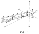
- FIG. 1 is a schematic representation of a sensor assembly of the disclosed response-ratioing angle of arrival determining system, showing its use.
- FIGS. 2A-2B are a side view cross-section and end view cross-section of a preferred embodiment of a sensor assembly of FIG. 1.
- FIG. 3A is a diagram illustrating the portion of the incident electromagnetic radiation energy which is reflected and transmitted by the gradient beam splitter, of the sensor assembly of FIG. 1, as a function of where on the gradient beam splitter the incident bundle of electromagnetic energy rays falls.
- FIG. 3B is a diagram illustrating the portion of incident electromagnetic radiation energy which falls on the first and second detectors of the sensor assembly of FIG. 1, as a function of where the incident bundle of electromagnetic energy rays falls upon the gradient beam splitter, FIG. 3B further illustrates the effects of blocking of rays arriving parallel to or near the optical axis by the first detector and the compensation for this effect with an auxiliary mirror system.
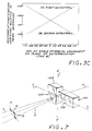
- FIG. 3C is a diagram of the response of the first and second detectors of the sensor assembly of FIG. 1.
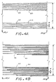
- FIGS. 4A-4B are plan views of wedged-area and stepped-area embodiments of the gradient beam splitter of the sensor assembly of FIG. 1.
- FIG. 5 is a schematic diagram of the geometry of detector width and spacing of the first and second detectors of the sensor assembly of FIG, 1, and for a practical application, the relationship of that geometry to the small variations in the angle of arrival which may be sensed in the plane of determination.
- FIGS. 6A-6B are side and end views, respectively, of a further embodiment of the sensor assembly of the disclosed system which utilizes refracting elements.
- FIG. 7 is a schematic representation of the use of two sensor assemblies to measure the angle of arrival in orthogonal planes and thereby determine the total angle.
- the system includes a sensor assembly 2 having an optical axis X-X and disposed so it will determine the angle of arrival ⁇ of a beam emanating from a remote source of electromagnetic energy along an axis 9.
- the angle of arrival ⁇ is determined in the plane formed by the optical axis X-X and axis Y-Y, by the sensor assembly 2 having its first detector 10 and second detector (not shown) disposed in the Y-Z plane.
- beam means any beam of electromagnetic radiation energy having rays which are substantially coherent or parallel one to the other when they reach the angle of arrival determining system.
- the sensor assembly will be completely immersed in the bundle of energy rays;emanating from a source remotely located at distances typical of the applications of such systems.
- the rays will be substantially parallel, emanating from, for example, a laser or a visible light source having a cross-section which is very small in comparison to the distance from the source to the sensor assembly 2. However, since these rays are substantially parallel, only certain ones of them will strike the detectors.
- the rays 8 outline the bundle of energy rays, approximately the size and shape of a detector, emanating from the remote source, which will ultimately strike the detectors in the sensor assembly 2.
- this invention is particularly concerned with overcoming the effects of changing refraction in the atmospheric path between the remote source and the sensor assembly 2 which changes the distribution of intensity of a beam emanating from the remote source.
- a beam emanating from such a remote source which may, at the source, have a steady, guassian disbribution of electromagnetic energy, as schematically illustrated by an energy profile curve 5.
- the beam may be changed by atmospheric refraction to a sharply non-uniform distribution of energy such as schematically illustrated in energy profile 6.
- energy profile 7 As the beam proceeds towards the sensor assembly 2, it may be again modified to a different distribution as schematically illustrated by energy profile 7. This access may continue until the beam arrives at the sensor assembly 2.
- the sensor assembly 1 is shown schematically in more detail in FIGS. 2A and 2B.
- the sensor 2 includes a housing 20 which is essentially an open, rectangular box with parallel sides, parallel ends and a bottom.
- a transparent optical window 22 is mounted at the top of the housing 20, parallel to the bottom.
- a first detector 10 and its substrate 14 are mounted on the inside surface of the transparent optical window 22.
- a second detector 12, of equal size and responsiveness to the incident energy as the first detector 10 and its substrate 16, are mounted on the bottom of the housing 20 and are aligned parallel to the first detector 10.
- Side mirrors 30, 31 are mounted against the inner sides of the housing 20 parallel to each other.
- Auxiliary mirrors 32, 33 are mounted on the bottom of the housing 20 at equal distances from the second detector 12. The auxiliary mirrors 32, 33 face toward the first detector 10 at equal and opposite angles.
- the dimensions of the housing 20 are determined by the type and size of the detectors 10, 12, which in turn depend on the amount of energy the system is required to collect.
- a sensor designed for determining the angle of arrival of, for example a laser beam of near-infrared radiation might have approximate dimensions, hight, width and length, of 1 inch, 1 inch and 1.5 inches respectively,
- Such a sensor could include silicon first and second detectors 10, 12 each approximately one-inch long and one-tenth inch wide.
- beams B1, B3 and B2 represent examples of ray bundles arriving from different directions at the sensor assembly 2.
- B1 represents a beam which might arrive at an angle + ⁇ at the extreme right edge of the field of view of sensor assembly 2.
- B2 represents a beam which might arrive at an angle - ⁇ at the opposite edge of the field fo view of the sensor assembly 2.
- B3 and B4 represent beams which might arrive nearly parallel to the optical axis X-X of the sensor assembly 2.
- the rays 11 outline the edges of the bundle of energy rays which, in each example of an incident beam, will strike the first detector 10 and the second detector 12. Rays outside of these will not strike a detector at all and will be absorbed by the absorbent coating on the walls of the housing 20.
- the rays 11 can be used to trace the path of the incident radiation to the detectors.
- the incident beam or more descriptively called "ray bundle”
- B2 which arrives at the edge of the field of view of sensor assembly 2. It passes through the window 22 and falls upon the gradient beam splitter 24.
- the beamsplitter 24 is coated with a partially reflecting material in such a way that some of the incident ray bundle B2 will be reflected from the coating and some of the incident ray bundle B2 will pass through the coating.
- Ray bundle B2 will be divided into a first component which is reflected from the surface of the gradient beam splitter 24 towards the first detector 10, and a second component which is transmitted by the gradient beam splitter 24 towards the second detector 12.
- a ray bundle arriving in the X-Y plane will fall upon the gradient beam splitter 24 at different points along the length of the beam splitter 24 depending on the angle of arrival ⁇ . This can be seen by inspection of ray bundles 81-84 in FIG. 2A.
- the beam splitter 24 is coated in such a way that the amount of reflected and transmitted energy rays depends on the place on the beam splitter 24 illuminated by the ray bundle.
- the gradient beam splitter 24 is provided with a coating having a reflectance and complementary transmittance which varies uniformly from one edge of the field of view to the other, for example, from 80 percent reflectance and 20 percent transmittance at point F to 20% reflectance and 80% transmittance at point G.
- Points F and G are the points in this cross-sectional view where the rays at the field-of-view edge strike the gradient beam splitter. It is the gradient in reflectance and transmittance of beam splitter 24 which allows for correlating the ratio of first detector 10 response to the second detector 12 response with angle of arrival.
- FIG. 2A if the rays 11 of a ray bundle arriving at an angle between + ⁇ and - ⁇ such as B1, B2 or 84 are followed to the first detector 10 and the second detector 12, it can easily be seen that the first detector 10 will respond to the first component of radiation which is divided from the bundle of rays by reflection from the gradient beam splitter 24.
- the second detector 12 will respond to the second component of radiation which is divided from the rays 11 by transmission through the gradient beam splitter 24.
- another path to the detectors 10, 12 is provided which is discussed shortly.
- FIG. 2A shows the rays arriving parallel to the X-Y plane, wherein the sensor assembly 2 determines the angle of arrival. Most likely, however, the incident beam will not lie parallel to the Y-Y plane. It may have a component which lies in the X-Z plane.
- FIG. 2B shows how such a component will be reflected from the side mirrors 30, 31.
- Typical rays in the X-Z plane of an incident beam are represented in FIG. 2B by the rays E.
- Rays E are reflected by side mirror 30 to the beam splitter 24 and then proceed to the detectors 10, 12 as described above.
- the rays E in FIG, 2B are shown arriving from a direction above the sensor assembly 2 and are refelected by side mirror 30. Rays arriving from below the sensor assembly 2 will be reflected from side mirror 31 in a similar manner.
- the reflection from the side mirrors 30, 31 does not change the position of the incident beam along the length of the beam splitter 24. Therefore the energy divided by reflection and transmission by the beam splitter is indicative of angle of arrival in the case of an out-ofplane arrival as well as an in-plane arrival.
- gradient beam splitters include a layer of partially reflecting material, usually a thin metallic film, deposited on glass or other transparent optical substrate.
- the reflecting layer is deposited in tapering thickness along the length of the beam splitter 24.
- the amount of reflection and complementary transmission of the beam splitter 24 depends on the thickness of the deposited layer.
- FIG. 3A shows how the reflectance and transmittance of the beam splitter 24 varies along its length when a uniformly tapering thickness of the partially-reflecting layer is used.
- the relative position of an incident energy ray bundle on the beam splitter 24 may be equated to the tangent of the angle of arrival, Tan ⁇ .
- the angle ⁇ illustrated at the point F on the diagram is +45 degrees and at the point G is -45 degrees, Tan ⁇ is +1 and -1 respectively, at these points.
- the total field of view is represented as 90 degrees.
- the beam splitter 24 is transparent to incident radiation. Except for the radiation for which an alternate path is provided to the detectors 10, 12 by way of the auxiliary mirrors 32, 33 under the circumstances described below, all other radiation will pass through the beam splitter 24 and be absorbed by the absorbent coating on the walls of the sensor assembly 2.
- the active areas of the first detector 10 and second detector 12 will begin to be blocked by the substrate 14 of the first detector 10.
- the response of the detectors 10, 12 to the incident energy will begin to decrease until, when the beam is directly parallel to the optical axis X-X, the response of the first and second detectors becomes zero.
- the range of angles at which this blocking occurs depends on the detector width and spacing between detectors.
- the portion of radiated energy which may fall upon the first detector 10 and second detector 12 as a function of relative -position of the ray bundle on the beam splitter 24 is shown in FIG. 3B.
- FIG. 3B shows that in the case of the sensor assembly illustrated, the sampling of incident energy reaching either the first or second detectors 10, 12 rapidly decreases between relative positions on the beam splitter 24 of plus and minus 0.2 (which corresponds to angles of arrival of plus and minus 11.3 degrees). The sharp fall-off of energy in this region is caused by blocking of the incident tray bundle by the first substrate 14. Energy reaching the detectors 10, 12 becomes zero at the relative position of zero which is on the optical axis X-X.
- auxiliary mirrors 32, 33 are placed so that they will take different, and unrestricted samples of the incident energy beam, and reflect them toward the beam splitter, Thus, radiation arriving at angles close to the optical axis X-X proceeds by an alternate path to the first and second detectors 10, 12.
- FIGS. 2A and 3B will assist in understanding the following explanation of the auxiliary mirror operation.
- the right auxiliary mirror 32 and left auxiliary mirror 33 are disposed behind a fully transparent section of the beam splitter 24 substrate.
- the auxiliary mirrors 32 and 33 are mounted on the bottom of the housing 20 and positioned on either side of and equidistant from the second detector 12, toward the walls of the housing.
- auxiliary mirror 33 Consider the energy reflected by auxiliary mirror 33. It can be seen that radiation is relayed to the first detector 10 by transmission through the beam splitter 24 and to the second detector 12 by reflection from the bottom of the beam splitter 24. The transmission and reflection from the bottom side of the beam splitter 24 is identical to that from the top. The division of the radiation components is achieved, therefore, in the same manner as when the incident rays fall upon the top of the beam splitter. However, the portion of incident energy arriving at the first detector 10 and second detector 12, as reflected from auxiliary mirror 33, is reversed from the case where, except for blockage by substrate 14, an incident beam would fall upon the top of the beam splitter.
- auxiliary mirrors 32, 33 are symmetrically placed about the optical axis X-X. Because the action of auxiliary mirror 33 is the same as for auxiliary mirror 32, but in "mirror image", the incident ray bundle reflected by auxiliary mirror 33 falls upon a portion of the beam splitter 24 having a ratio of reflectance to transmittance exactly complementary to the place on the beam splitter where the ray bundle reflected by auxiliary mirror 32 falls. As a result, the sum of the radiation reaching the first detector 10 and second detector 12 by relay from the auxiliary mirrors 32, 33 is the average of the radiation received by complementary reflectance and transmittance of the beam splitter 24.
- This average radiation is the same as would be received from rays reflected and transmitted from beam splitter 24, at points near its center, corresponding to the same angle of arrival, except for blockage by substrate 14. Therefore, the radiation reaching the detectors 10, 12 is indicative of the angle of arrival as though the incident rays reached detectors 10, 12 by reflection and transmission from the central portion of the beam splitter 24.
- FIG. 3B shows that an amount of radiation energy is lost at the first detector 10 and second detector 12 when an arriving beam is partially or fully blocked by the first detector substrate 14. Also in FIG. 3B, the dotted line illustrates the portion of incident energy reflected by one auxiliary mirror 32 to the beam splitter 24.
- FIG. 3C illustrates the response of the detectors 10, 12 to all incident radiation after compensation by the action of the auxiliary mirrors 32, 33 in combination with the beam splitter 24.
- the response of the first detector 10 is curve A and of the second detector 12 is curve B.
- the curves are seen to be analagous, respectively, to the variation in reflectance and transmittance of the beam splitter 24 depicted in FIG, 3A, and therefore indicative of the angle of arrival.
- the curves A, B vary linearly as a function of the tangent of the angle of arrival Tan ⁇ .
- the ratio of the difference to the sum of the responses of the first detector 10 and the second detector 12 is also linear function with Tan ⁇ .
- ⁇ Tan ⁇ 1 K (A-B/A+B)
- the result of taking the said ratio is, therefore, indicative of the angle of arrival ⁇ .
- the said ratio can be determined electronically by conventional and well known signal processing means.
- the beam splitter 24 may be commercially obtained.
- the reglecting film on the surface of the beam splitter 24 is deposited in tapering thickness along the dimension which is at right angles to the length of the detectors.
- the deposited gradient is sandwiched between two substrates of the same thickness, one for mechanical support and the other to supply necessary optical symmetry.
- the amount of reflectance and complementary transmittance of a beam splitter depends principally on the thickness of the film. However, in such films, the transmittance is affected by absorption as well as reflectance of the film. The absorption is an efficiency loss which is not desired.
- FIGS. 4A-4B illustrated therein are plan views of two alternate embodiments of the gradient beam splitter 24.
- the disclosed embodiments may be referred to a as wedged-area ans stepped-area film coatings, respectively.
- the coated, striped areas 40 are fully reflective and the uncoated areas 42 of the substrate are fully transparent. This eliminates absorption of the film as a factor in the transmission of the beam energy.
- these embodiments are more easily made than the beam splitter having tapered-thickness film.
- the coating 40 shown is an example of a repetitive pattern which may be repeated across the width H of the beam splitter 24.
- Dimension H is parallel to the length of the first detector 10 and second detector 12 and depends on the size of detectors needed to capture the desired amount of energy.
- Dimension L is perpendicular to the length of the first and second detectors 10, 12 and may be selected depending on the field of view desired for the sensor assembly 2.
- the width W of each lineal element of the stepped-area coating may be .001 inch.
- the maximum width of combined elements may be .005 inch. This substantially cancels the effects of non-uniform scintels larger than .005 inch in a beam disturbed by atmospheric scintillation as explained in subsequent paragraphs, Coating elements of .001 inch are consistent with manufacturing techniques for easy repeatability.
- the dimensions 1 in the step-wise direction of the coating elements are selected to be the same as the width of each detector 10, 12.
- the incident ray bundle is divided by a constant factor of both reflection and transmission.
- all clusters of rays in the ray bundle larger than the widest area of the opaque stripes 40 (or transparent stripes 42) will be divided by the said constant.
- the constant factor of energy division is substantially maintained. The rays striking the detectors 10, 12 are still in the ratio determined by the average reflection and complementary transmission of the area on the beam splitter 24 where the ray bundle falls.
- the first and second detectors 10, 12 are responsive to the average of the energy rays striking each over its length. Therefore, for practical beam sizes, when the responses of the first and second detectors 10, 12 are summed and the ratio taken as described in Equation 1, Tan ⁇ is not affected by the shifting energy distri butions across the width of the beam splitter 24. The angle of arrival may therefore, be unambiguously determined.
- the variation in energy distribution may be in the plane of measurement or any other plane. Still referring to FIGS. 4A-B, if variations occur in energy distribution in the plane of measurement, this variation will occur along dimension L of the beam splitter 28. There will be a small effect on angle of arrival determination resulting from the finite size of the ray bundle in this dimension. While, as has already been said, the optical properties of the beam splitter 24 are uniform across dimension H, there is, of course, a variation of these properties along dimension L of beam splitter 24.
- This variation coupled with the fact the ray bundle of interest has a width equal to that of the detectors 10, 12, can produce slight variations in the determined angle if, in this direction, the energy rays are concentrated toward one edge or the other of the ray bundle.
- the variations in the determined angle are dependent on the detector width and spacing.
- FIG. 5 schematically illustrates the detector width W and spacing S between the first detector 10, the second detector 12 and the beam splitter 24.
- Incident energy rays 11 are shown falling upon the beam splitter 24 at points P, P′ and P ⁇ within the field of view.
- the reflectance and transmittance of the beam splitter along dimension L vary equally but are complementary in value.
- the bundle of energy rays 11 incident on each detector 10, 12 is integrated over the detectors width W. If the segments of the beam represented by rays 11 are uniform, the detector response will be an average value indicative of the angle of arrival associated with point P on the beam splitter. If the rays 11 of the beam are concentrated at one edge, then in the extreme cases, the detector response will be indicative of the angle of arrival associated with points P′ or P ⁇ on the beam splitter.
- d ⁇ Tan ⁇ 1 (W/2S)
- the spacing of the detectors may be determined to minimize angular error. If a permissible error is chosen, as for example, an error d ⁇ as to be 5 degrees for a beam incident at zero degrees (parallel to the optical axis) the spacing S will be 5.71 times the detector width W.
- FIGS. 6A-6B schematically illustrate the alternate embodiment of the invention.
- This embodiment includes a first transparent optical substrate 201, a second transparent optical substrate 202, a first detector 10, a second detector 12, and an auxiliary prism 232.
- the first substrate 201 is cemented to the second substrate 202.
- the gradient beam splitter 24 is deposited on one of the first and second substrates 201, 202.
- the auxiliary prism 232 is laterally displaced from detector 10 and serves the same function as the two auxiliary mirrors 32, 33 shown in FIGS. 2.A-B.
- the auxiliary prism 232 relays energy rays 11 to the detectors 10, 12 when the incident ray bundle is near-parallel or parallel with the optical axis X-X and therefore blocked by the detector substrate 14.
- the prism 232 relays energy by way of an auxiliary portion of the beam splitter 24 laterally displaced outside of the normal field of view rather than a portion within the field of view as do the auxiliary mirrors 32, 33 in the preferred embodiment.
- the portion of the beam splitter 24 illuminated by the prism 232 is coated with the same pattern as the part of the beam splitter 24 which is blocked from rays parallel or near-parallel to the axis X-X.
- the total energy which reaches the first detector 10 and the second detector 12 from the auxiliary prism 232 in combination with the reflection from and complementary transmission through the auxiliary portion of the beam splinter 24, is the same as though there were no blockage by substrate 14.
- the optical substrates 201, 202 introduce an ambiguity in the angle of arrival determination.
- a beam arriving in a plane which is not the plane of determination of angle of arrival will be bent onto the gradient beam splitter 24 at an angle nearer to the normal to the beam splitter surface than a beam which has the same angle of arrival but is in the plane of determination. Such a beam will appear to be at a lesser angle of arrival than its true angle.
- a correction factor may be determined by well-known methods of ray traceing for the selected dimensions and materials from which the optical substrates 201, 202 are made.
- Equation 3 ⁇ corr is the corrected angle of arrival, ⁇ read is the read or indicated angle of arrival in the plane of determination and ⁇ read is the read or indicated angle of arrival in the plane orthogonal to the plane of determination.
- the system will read 36 degrees for a beam having a component of 45 degrees in the X-Y plane and a component of 45 degrees in the X-Z plane.
- the alternate embodiment can be smaller and more durable than the preferrred design. It presents structural advantages in severe environments. It also has smaller polarization effects.
- FIGS. 6A-B requires careful selection of substrate and cement materials to match the indexes of refraction and to substantially eliminate air bubbles.
- Sensor assemblies in accordance with this invention may be paired and oriented as schematically illustrated in FIG. 7 to determine the angle of arrival in two orthogonal planes.
- the axis of the electromagnetic energy emanating from a remote source 9 forms a compound angle A with respect to the optical axis X-X of the two sensor assemblies 100, 103.
- a general arrangement is shown wherein the right-hand sensor assembly 100 determines the angle of arrival ⁇ in the X-Y plane and the left-hand sensor assembly 103 determines the angle of arrival ⁇ in the X Z plane.
- the first detector 102 and the second detector are disposed lengthwise and parallel along the Z-Z axis.
- the first detector 105 and the second detector are disposed lengthwise and parallel along the Y-Y axis.
- the detector responses which are indicative of the angle ⁇ and the angle ⁇ may be combined by well-known signal processing means to determine the total angle of arrival A.
- the general arrangement of the sensor assemblies 100, 103 shown in FIG. 7 may cover a field of view of up to 90 degrees by 90 degrees.
- a multiplicity of pairs of sensor assemblies may be disposed to cover a larger desired field of view.
Landscapes
- Physics & Mathematics (AREA)
- Electromagnetism (AREA)
- Engineering & Computer Science (AREA)
- General Physics & Mathematics (AREA)
- Radar, Positioning & Navigation (AREA)
- Remote Sensing (AREA)
- Measurement Of Radiation (AREA)
- Photometry And Measurement Of Optical Pulse Characteristics (AREA)
Claims (15)
dadurch gekennzeichnet,
daß der Strahlteiler (24) ein Substrat aufweist, das variierende Anteile der einfallenden Strahlung als Funktion der Strecke entlang des Strahlteilers in einer Richtung parallel zu den Seiten (30, 31) der Struktur (20; 201, 202) transmittiert und reflektiert; und
daß jeder der Detektoren (10, 12) in einer Richtung parallel zu den Seiten (30, 31) der Struktur (20; 201, 202) eine Breite aufweist, die im Vergleich zum Strahlteiler in der gleichen Richtung klein ist.
Applications Claiming Priority (2)
| Application Number | Priority Date | Filing Date | Title |
|---|---|---|---|
| US3342287A | 1987-04-02 | 1987-04-02 | |
| US33422 | 2001-12-27 |
Publications (2)
| Publication Number | Publication Date |
|---|---|
| EP0308504A1 EP0308504A1 (de) | 1989-03-29 |
| EP0308504B1 true EP0308504B1 (de) | 1992-08-12 |
Family
ID=21870314
Family Applications (1)
| Application Number | Title | Priority Date | Filing Date |
|---|---|---|---|
| EP88904729A Expired EP0308504B1 (de) | 1987-04-02 | 1988-03-07 | Richtungsbestimmender sensor mit bestimmung des empfangsignalverhältnisses |
Country Status (5)
| Country | Link |
|---|---|
| EP (1) | EP0308504B1 (de) |
| JP (1) | JPH0677055B2 (de) |
| DE (1) | DE3873670T2 (de) |
| IL (1) | IL85708A (de) |
| WO (1) | WO1988008142A1 (de) |
Families Citing this family (2)
| Publication number | Priority date | Publication date | Assignee | Title |
|---|---|---|---|---|
| GB2314985B (en) * | 1996-07-04 | 2001-06-13 | Marconi Gec Ltd | Interferometry |
| US20070297805A1 (en) * | 2006-06-23 | 2007-12-27 | William Rabinovich | Optical communication system with cats-eye modulating retro-reflector (mrr) assembly, the cats-eye mrr assembly thereof, and the method of optical communication |
Family Cites Families (2)
| Publication number | Priority date | Publication date | Assignee | Title |
|---|---|---|---|---|
| US3084261A (en) * | 1960-02-24 | 1963-04-02 | Gen Precision Inc | Sun tracker |
| US3494699A (en) * | 1966-12-09 | 1970-02-10 | Bell Telephone Labor Inc | Optical beam position sensor |
-
1988
- 1988-03-07 DE DE8888904729T patent/DE3873670T2/de not_active Expired - Fee Related
- 1988-03-07 WO PCT/US1988/000661 patent/WO1988008142A1/en not_active Ceased
- 1988-03-07 EP EP88904729A patent/EP0308504B1/de not_active Expired
- 1988-03-07 JP JP63504539A patent/JPH0677055B2/ja not_active Expired - Lifetime
- 1988-03-11 IL IL8885708A patent/IL85708A/xx not_active IP Right Cessation
Also Published As
| Publication number | Publication date |
|---|---|
| JPH01503564A (ja) | 1989-11-30 |
| EP0308504A1 (de) | 1989-03-29 |
| IL85708A (en) | 1991-08-16 |
| JPH0677055B2 (ja) | 1994-09-28 |
| IL85708A0 (en) | 1988-08-31 |
| WO1988008142A1 (en) | 1988-10-20 |
| DE3873670D1 (de) | 1992-09-17 |
| DE3873670T2 (de) | 1993-03-18 |
Similar Documents
| Publication | Publication Date | Title |
|---|---|---|
| US4207467A (en) | Film measuring apparatus and method | |
| US5022725A (en) | Optical sensor | |
| US5596320A (en) | System for detection of ice, water, glycol solution, and other chemical species | |
| US6118119A (en) | Spectral analyzer with wavelength and direction indicator | |
| US4641524A (en) | Optical humidity sensor | |
| US4325633A (en) | Apparatus for determining of angle of incidence of electromagnetic energy | |
| US4824245A (en) | Response ratioing angle of arrival sensor that is responsive to scintillation | |
| US4320967A (en) | Apparatus for measuring a radiation affecting parameter of a film or coating | |
| CN1057832C (zh) | 非接触测量透明材料制成的被测物厚度的设备 | |
| US6417924B1 (en) | Surface plasmon sensor obtaining total reflection break angle based on difference from critical angle | |
| CA1333756C (en) | Process for the production of a telecentric light beam, device for carrying out this process and process for the production of an hoe | |
| EP0575132A1 (de) | Optische Messvorrichtung | |
| GB2189882A (en) | Apparatus for measuring the thickness of a surface layer | |
| US5828447A (en) | Orientation location system of an observation instrument | |
| EP0308504B1 (de) | Richtungsbestimmender sensor mit bestimmung des empfangsignalverhältnisses | |
| US9891041B2 (en) | Apparatus and method for measuring thickness of transparent and/or translucent mediums using a reflecting signal that is normal or near normal to the mediums | |
| US4792695A (en) | Contact-free measuring apparatus having an F-theta-corrected, catadioptric objective and method for using the same | |
| US20160153902A1 (en) | Device for measuring the scattering of a sample | |
| EP0650043A1 (de) | Optisches System für eine Reflexionsmessungsvorrichtung mit hoher Empfindlichkeit | |
| US5103088A (en) | Optical sensor device using a dielectric transparent spherical-shell section | |
| JP3354698B2 (ja) | 平面度測定装置 | |
| US3093742A (en) | Extended radiation micrometer gage | |
| US5377010A (en) | Air path beam combining optics for a ring laser | |
| JP2668948B2 (ja) | 光センサー | |
| KR100749829B1 (ko) | 3차원 광측정장치 |
Legal Events
| Date | Code | Title | Description |
|---|---|---|---|
| PUAI | Public reference made under article 153(3) epc to a published international application that has entered the european phase |
Free format text: ORIGINAL CODE: 0009012 |
|
| 17P | Request for examination filed |
Effective date: 19881103 |
|
| AK | Designated contracting states |
Kind code of ref document: A1 Designated state(s): DE FR GB IT NL |
|
| 17Q | First examination report despatched |
Effective date: 19910207 |
|
| RAP3 | Party data changed (applicant data changed or rights of an application transferred) |
Owner name: SANTA BARBARA RESEARCH CENTER |
|
| GRAA | (expected) grant |
Free format text: ORIGINAL CODE: 0009210 |
|
| AK | Designated contracting states |
Kind code of ref document: B1 Designated state(s): DE FR GB IT NL |
|
| REF | Corresponds to: |
Ref document number: 3873670 Country of ref document: DE Date of ref document: 19920917 |
|
| ET | Fr: translation filed | ||
| ITF | It: translation for a ep patent filed | ||
| PLBE | No opposition filed within time limit |
Free format text: ORIGINAL CODE: 0009261 |
|
| STAA | Information on the status of an ep patent application or granted ep patent |
Free format text: STATUS: NO OPPOSITION FILED WITHIN TIME LIMIT |
|
| 26N | No opposition filed | ||
| PGFP | Annual fee paid to national office [announced via postgrant information from national office to epo] |
Ref country code: NL Payment date: 19990224 Year of fee payment: 12 |
|
| PGFP | Annual fee paid to national office [announced via postgrant information from national office to epo] |
Ref country code: DE Payment date: 19990226 Year of fee payment: 12 |
|
| REG | Reference to a national code |
Ref country code: GB Ref legal event code: 732E |
|
| PGFP | Annual fee paid to national office [announced via postgrant information from national office to epo] |
Ref country code: FR Payment date: 20000911 Year of fee payment: 13 |
|
| PG25 | Lapsed in a contracting state [announced via postgrant information from national office to epo] |
Ref country code: NL Free format text: LAPSE BECAUSE OF NON-PAYMENT OF DUE FEES Effective date: 20001001 |
|
| NLV4 | Nl: lapsed or anulled due to non-payment of the annual fee |
Effective date: 20001001 |
|
| PG25 | Lapsed in a contracting state [announced via postgrant information from national office to epo] |
Ref country code: DE Free format text: LAPSE BECAUSE OF NON-PAYMENT OF DUE FEES Effective date: 20010103 |
|
| PGFP | Annual fee paid to national office [announced via postgrant information from national office to epo] |
Ref country code: GB Payment date: 20010420 Year of fee payment: 14 |
|
| PG25 | Lapsed in a contracting state [announced via postgrant information from national office to epo] |
Ref country code: FR Free format text: LAPSE BECAUSE OF NON-PAYMENT OF DUE FEES Effective date: 20011130 |
|
| REG | Reference to a national code |
Ref country code: FR Ref legal event code: ST |
|
| REG | Reference to a national code |
Ref country code: GB Ref legal event code: IF02 |
|
| PG25 | Lapsed in a contracting state [announced via postgrant information from national office to epo] |
Ref country code: GB Free format text: LAPSE BECAUSE OF NON-PAYMENT OF DUE FEES Effective date: 20020307 |
|
| GBPC | Gb: european patent ceased through non-payment of renewal fee |
Effective date: 20020307 |
|
| PG25 | Lapsed in a contracting state [announced via postgrant information from national office to epo] |
Ref country code: IT Free format text: LAPSE BECAUSE OF NON-PAYMENT OF DUE FEES Effective date: 20050307 |