EP0308609A2 - Dispositif d'alimentation du fil pour des machines textiles à consommation de fil temporairement différent, notamment our des machines à tricoter - Google Patents
Dispositif d'alimentation du fil pour des machines textiles à consommation de fil temporairement différent, notamment our des machines à tricoter Download PDFInfo
- Publication number
- EP0308609A2 EP0308609A2 EP19880111566 EP88111566A EP0308609A2 EP 0308609 A2 EP0308609 A2 EP 0308609A2 EP 19880111566 EP19880111566 EP 19880111566 EP 88111566 A EP88111566 A EP 88111566A EP 0308609 A2 EP0308609 A2 EP 0308609A2
- Authority
- EP
- European Patent Office
- Prior art keywords
- thread
- tensioning element
- delivery device
- movement
- guide arm
- Prior art date
- Legal status (The legal status is an assumption and is not a legal conclusion. Google has not performed a legal analysis and makes no representation as to the accuracy of the status listed.)
- Withdrawn
Links
- 238000009940 knitting Methods 0.000 title claims abstract description 35
- 239000004753 textile Substances 0.000 title claims abstract description 5
- 230000033001 locomotion Effects 0.000 claims abstract description 66
- 230000015572 biosynthetic process Effects 0.000 claims abstract description 4
- 230000001419 dependent effect Effects 0.000 claims description 5
- 230000001105 regulatory effect Effects 0.000 claims description 5
- 230000007423 decrease Effects 0.000 claims description 3
- 238000003860 storage Methods 0.000 description 17
- 230000008859 change Effects 0.000 description 9
- 230000000694 effects Effects 0.000 description 7
- 239000000463 material Substances 0.000 description 7
- 230000003247 decreasing effect Effects 0.000 description 4
- 230000004888 barrier function Effects 0.000 description 3
- 239000003990 capacitor Substances 0.000 description 3
- 238000010276 construction Methods 0.000 description 2
- 238000013016 damping Methods 0.000 description 2
- 238000010586 diagram Methods 0.000 description 2
- 238000006073 displacement reaction Methods 0.000 description 2
- 230000005284 excitation Effects 0.000 description 2
- 230000007257 malfunction Effects 0.000 description 2
- 238000000034 method Methods 0.000 description 2
- 230000008569 process Effects 0.000 description 2
- 230000009467 reduction Effects 0.000 description 2
- 230000002123 temporal effect Effects 0.000 description 2
- 210000003371 toe Anatomy 0.000 description 2
- 230000007704 transition Effects 0.000 description 2
- 230000001133 acceleration Effects 0.000 description 1
- 238000009434 installation Methods 0.000 description 1
- 238000004519 manufacturing process Methods 0.000 description 1
- 238000001208 nuclear magnetic resonance pulse sequence Methods 0.000 description 1
- 230000035515 penetration Effects 0.000 description 1
- 230000002093 peripheral effect Effects 0.000 description 1
- 238000004904 shortening Methods 0.000 description 1
- 230000011664 signaling Effects 0.000 description 1
- 230000003068 static effect Effects 0.000 description 1
- 230000001629 suppression Effects 0.000 description 1
- 238000004804 winding Methods 0.000 description 1
Images



Classifications
-
- D—TEXTILES; PAPER
- D04—BRAIDING; LACE-MAKING; KNITTING; TRIMMINGS; NON-WOVEN FABRICS
- D04B—KNITTING
- D04B15/00—Details of, or auxiliary devices incorporated in, weft knitting machines, restricted to machines of this kind
- D04B15/38—Devices for supplying, feeding, or guiding threads to needles
-
- D—TEXTILES; PAPER
- D04—BRAIDING; LACE-MAKING; KNITTING; TRIMMINGS; NON-WOVEN FABRICS
- D04B—KNITTING
- D04B15/00—Details of, or auxiliary devices incorporated in, weft knitting machines, restricted to machines of this kind
- D04B15/38—Devices for supplying, feeding, or guiding threads to needles
- D04B15/48—Thread-feeding devices
Definitions
- the invention relates to a thread delivery device for textile machines with different times of thread usage, in particular knitting and warp knitting machines, with a rotatably mounted thread delivery element which promotes the thread without slippage, to which thread guide elements are assigned and which is coupled to a speed-adjustable electric drive motor, with a thread path behind the thread supply element arranged, acting on the thread coming from the thread supplying thread tensioning element, which is movably mounted and is subjected to a prestressing force determining the thread tension, a thread reserve being formed between the thread tensioning element and at least one thread guide element, the size of which is determined by the respective position of the thread tensioning element, and with the speed of the drive motor depending on the thread consumption of the thread consumer regulating electrical control means.
- the carriage carrying the needle lock parts and using them to control the needle movement executes a reciprocating movement over the effective width of the needle bed.
- the Thread guides are moved back and forth accordingly.
- the carriage makes an overstroke with respect to the last knitting needles, during which no thread is processed and is therefore removed from the thread source.
- the length of the thread travel path between the stationary thread source and the thread guide carrying out a linear, reciprocating movement undergoes a permanent change.
- a so-called thread tensioner is used in practice, which holds the thread material that is not required in a thread reserve and keeps it under tension until after the reversing movement of the The first needle is knitted again on the carriage and the thread guide, or the thread reserve formed is released due to the length of the thread path to the thread guide, which length increases as the movement continues.
- similar conditions occur in the manufacture of socks and stockings with heels and toes on small circular knitting machines if the needle cylinder for knitting the heel or toe is moved back and forth in the so-called pendulum movement in the circumferential direction.
- a thread brake also works a thread retrieval device known from FR-OS 2538 419 for flat knitting machines or hosiery or sock knitting machines operating in the pendulum, in which the thread tension is sensed on the thread path between a fixed thread guide element and the thread guide and one in the thread path in front of the fixed thread guide element arranged thread braking and return device is adjusted such that the thread tension on the thread guide remains approximately within a predetermined fluctuation range.
- this device which operates with limit switches controlled by the thread sensing element, permits only a very imperfect and rough influence on the thread tension, the thread must be drawn from the needles themselves via the thread brake from the bobbin, so that the thread only with a relatively large thread tension can be processed.
- disturbances in the thread run-off conditions from the bobbin can impair the uniformity of the knitted goods.
- the arrangement is such that travel sensors are connected to the drive elements of the carriage and the thread guide of the flat knitting machine, which emit characteristic electrical signals for the respective position and speed of the carriage and the thread guide, with the help of which the drive motor of the thread delivery element, taking into account the changes occurring during the back and forth movement of the thread guide changes in the thread path to the thread guide, is controlled in accordance with the temporal course of the thread consumption.
- the drive motor is an actuator in an electrical control loop, the reference variable of which is formed by the signals mentioned.
- a thread tensioning element is arranged after the thread delivery element in the thread travel path If the thread tension decreases, a thread reserve temporarily builds up, which is reduced again in the further course of operation.
- This thread tensioning element is designed in the form of a thread guide arm which is rotatably or pivotably mounted about a fixed axis of rotation and which carries a thread eyelet at the end which, in cooperation with fixed thread guide elements, generates an approximately V-shaped thread path.
- the thread guide arm is coupled in the area of its bearing point to a spiral spring which is fixed at one end and which is an adjustable predetermined one on the thread guide arm Exerts pre-tension, which determines the size of the thread tension.
- the installation of the various displacement sensors on the flat knitting machine requires intervention in the machine.
- these displacement sensors are necessarily expensive because they capture the entire lifting movement of the carriage and the thread guide over the often relatively long needle bed and, moreover, must be at least partially adjustable according to the width of the work piece being processed. Since the drive motor of the thread delivery element is controlled only in a rigid, predetermined dependency on the reciprocating movement of the carriage and the thread guide, the coordination and the adjustment of the individual links of the control chain are critical.
- the object of the invention is to create a thread delivery device for textile machines with different times of thread consumption, for example flat knitting machines or circular knitting machines etc. which temporarily work in a pendulum motion, which allows a thread delivery with constant, Allow thread tension that can be set as desired, even under operating conditions, which, for example in connection with the reversal of movement of the thread guide of a flat knitting machine or the needle cylinder of a circular knitting machine, reliably prevent a temporary formation of loops in the thread or the occurrence of excessive thread tension peaks.
- the thread delivery device mentioned at the outset is characterized according to the invention in that the thread tensioning element is equipped with a sensor is coupled, which, depending on the adjustment movement of the thread tensioning element taking place within a working area, emits a signal characterizing its respective position and / or movement to an electrical circuit containing the drive motor, by means of which the drive motor can be stopped if the thread tensioning element during a movement in the sense an increasing thread reserve reaches a limit position of its working area, that after this limit position of the working area a further movement range of the thread tensioning element is provided, into which the thread tensioning element can be moved with decreasing thread tension due to the pre-tensioning force acting on it with the drive motor at a standstill and that thread rest means are assigned to the further movement range are on which the thread returned from the thread tensioning element and kept under tension can be temporarily deposited with the formation of an additional thread reserve.
- the thread tensioning element stores thread material occurring outside its normal working range when the thread delivery element is at a standstill, so that the occurrence of thread loops, for example when the movement of a needle cylinder working in the pendulum motion is avoided, without additional measures being necessary.
- the thread is kept under tension so that perfect thread delivery conditions are always guaranteed.
- the thread tensioning element is part of the thread tension on the Thread travel behind the thread delivery element constantly on a controller holding by the pretensioning force, the transducer emitting a signal characteristic of the manipulated variable of the control loop to the electronic circuit working as part of the controlled system when the thread tensioning element moves within the working range.
- the thread tensioning element and the controller which only move within its working area, continuously regulate the drive motor of the thread delivery element in such a way that the thread tension is constantly adjusted to that caused by the Thread tensioning element acting prestressing certain setpoint size remains regulated.
- the thread tensioning element moves under the effect of the pretensioning force into the additional movement range while the drive motor of the thread delivery element is stopped. It retrieves the thread that is no longer removed and places it on the thread support until the thread is removed again after the carriage has moved back and the additional thread reserve is thus first released and the thread tensioning element is moved back into its working area. As soon as it enters this, the drive motor of the thread delivery element is started again and its speed is regulated in accordance with the thread consumption in such a way that the thread tension is always kept constant.
- the thread tensioning element is assigned position-dependent means, by means of which the biasing force acting on the thread tensioning element can be increased by an optionally adjustable predetermined value when the thread tensioning element reaches a predetermined position in its movement.
- This position is expediently the aforementioned limit position of the further range of movement of the thread tensioning element or a position lying within this further range of movement.
- This position of the thread tensioning element can be controlled in a structurally simple manner in such a way that a position transmitter is coupled to the thread tensioning element which emits an electrical signal when the predetermined position is reached.
- the position transmitter can also be combined with or formed by the sensor, which is coupled to the thread tensioning arm anyway, in order to emit a position-dependent control signal for the control circuit or at least a stop signal for the drive motor of the thread delivery element when the thread tensioning element is at decreasing thread tension reaches its limit position towards the further range of motion.
- the thread tensioning element has a rotatably mounted thread guide arm which is coupled to the thread and with which a measuring sensor which couples the angular position of the thread guide arm is coupled.
- This transducer can be of any type, preferably non-contact, but it has proven to be advantageous if the transducer has an angular encoder element coupled to the thread guide arm which can be scanned by photo-optical signaling means.
- Any appropriate transfer function of the transmitter which is also suitable for the static and dynamic control behavior of the controller, can be achieved with simple means if the angle transmitter element has an optically scannable disk or edge-bearing disk, of which at least one track or edge is attached to the transmitter and at least one is attached to it Position transmitter is assigned.
- the means for increasing the pretensioning force acting on the thread tensioning element have a device for determining the state of movement and, if appropriate, the direction of movement of the thread tensioning element, and this device enables or increases the pretensioning force only when the thread tensioning element is in motion.
- the pretensioning force itself can be generated in different ways. It only has to be adjustable and, if possible, should be constant regardless of the angle, at least in the working area of the thread tensioning element. These conditions can be met in a very simple manner if the thread tensioning element is coupled to an electromagnetic torque transmitter generating the biasing force, the torque which it emits - and thus the biasing force - in a very simple manner by corresponding Influencing the electrical input variables can be adjusted.
- the means for increasing the pretensioning force then have a circuit stage which influences the input voltage or the input current of the torque transmitter.
- a device for determining the state of motion of the thread tension element can also be provided, which has a differentiating element that processes an output signal or a signal derived therefrom from the measured value or position transmitter.
- the thread support means which receive the thread material withdrawn from the thread tensioning element into the additional thread reserve are to be designed according to the geometric conditions of the path of movement of the thread tensioning element (linear or circular) and the amount of the thread material to be picked up. You must ensure that the thread material is held securely and, at the same time, allow the thread to be removed properly if the additional thread reserve is released.
- the thread support means have thread support elements arranged distributed in the movement area of the thread guide arm carrying the thread guide means.
- These thread support elements are expediently arranged on at least one concentric circle around the axis of rotation of the thread guide arm. They can have bolts or rollers provided with thread take-up means, for example grooves or grooves at least the rollers are rotatably mounted and are at least associated with the piece of thread running from the thread guide means to the thread consumer.
- the thread delivery element is stationary, so that no thread is pulled from the thread delivery element.
- the piece of thread that runs from the thread consumer for example the last knitting needle, to the thread guide arm must be withdrawn. In order to avoid the occurrence of excessive friction, it is advisable to pull at least this piece of thread over rotatably mounted rollers.
- the thread support elements can advantageously be arranged projecting on one side on a flat carrier arranged on a housing carrying the thread supply element, so that the thread support can easily be visually checked and corrected by hand if errors occur. Since the thread in the area of the thread guide arm lies on a substantially V-shaped thread path, at the apex of which the thread eyelet of the thread guide arm is seated, the thread support elements are arranged at least in groups to different extents from the carrier, so that the two rest perfectly against the eyelet running thread pieces is guaranteed.
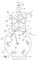
- the thread delivery device shown in FIGS. 1 to 3 has a housing 1, which carries a holder 2, which is set up for attachment to the frame ring of a circular knitting machine, not further shown, and in the area of which electrical connection devices for the inside of the Housing 1 housed electrical and electronic components are arranged.
- an electric stepping motor 3 is arranged in the manner shown in FIG. 3, which projects with its shaft through a corresponding opening in the front wall of the housing and drives a thread wheel 5 which is non-rotatably mounted on the shaft.
- the thread wheel 4 consists of a hub 5 placed on the shaft and a number of essentially U-shaped wire brackets 6 connected to the end of the hub 4, each of which has an essentially axially parallel thread support part 7 and an adjoining run-in slope 8.
- the thread wheel 4 can also be designed in the form of a thread drum or a rod cage and carry an end disk indicated in Fig. 3 at 7a, in which the rods bent at one end in accordance with the chamfer 8 are anchored with their straight thread support part 7, as shown in Fig 3 is illustrated.
- the thread wheel 4 forming the thread delivery element is assigned fixed thread guide elements which are arranged on the housing 1 and consist of an inlet eyelet 10 provided on a housing-fixed holder 9 and a thread eyelet 11 arranged on the housing 1 on the thread outlet side of the thread wheel.
- the thread 12 coming from a thread source (not shown further), for example a spool, runs through the inlet eyelet 10 via an adjustable thread-disk brake 13 arranged on the holder 9 onto the thread wheel 4 in the region of the run-up bevels 8, which open up the thread windings that form push the thread support parts 7 of the stirrups or rods 6, on which a storage roll consisting of a number of thread turns is thus formed, which together with the narrow support areas 7 ensures an essentially slip-free entrainment of the thread 12 on the circumference of the thread wheel 4.
- a thread source for example a spool
- the thread 12 runs tangentially from the thread wheel 4, namely at the same speed at which the thread also tangentially runs onto the thread wheel 4 through the inlet eyelet 10.
- the thread 12 coming from the storage reel on the thread wheel 4 runs through a thread eyelet 14 at the end of a thread guiding arm forming a movable thread tensioning element, at the other at 15 pivotably mounted on the housing 1, and from there back to the second stationary thread eyelet 11, which is at a distance below and is arranged next to the thread wheel 4.
- the thread goes from the second thread eyelet 11 to a thread consumer, not shown, in a knitting machine via the thread guide to the needles of a knitting point.
- the pivotably mounted thread guide arm 16 with its thread eyelet 14 between the circumference of the thread wheel 4 and the fixed second thread eyelet 11 normally forms the substantially V-shaped one shown in FIG. 1 extended thread path, which represents a thread reserve, the size of which depends on the angular position of the thread guide arm 16.
- the axis of rotation 15 of the thread guide arm 16 lies with the axis of the hub 5 of the thread wheel 4 in a common plane of symmetry, the arrangement being such that the thread guide arm 16 lying in this plane of symmetry in FIG. 1 has its eyelet 14 at a distance from the circumference of the thread wheel 4 is approximately at the level of the second fixed thread eyelet 11.
- the axis of the eyelet 14 extends in this position of the thread guide arm 16 in the vertical direction.
- a small DC motor 18 (FIG. 3) is fastened to the front wall of the housing, which projects with its shaft 190 through a corresponding opening in the front wall of the housing and is rotatably coupled to the thread guide arm 16 which is bent inwards at its open end.
- the permanently excited DC motor 18, which is preferably designed as a so-called bell-rotor motor, acts as an electrical torque transmitter and can also be replaced by a torque transmitter constructed similarly to the measured value of a moving-coil measuring instrument etc. It exerts on the thread guide arm 16 a precisely predetermined, adjustable pretensioning torque, which corresponds to a corresponding pretensioning force acting on the eyelet 14, with which the thread guide arm 16 is acted upon.
- This pretensioning force is opposite to the tensile force exerted by the thread 12 guided through the eyelet 14 and dependent on the thread tension, ie with reference to FIG. 1 this pretensioning force points to the left or the pretensioning torque is directed counterclockwise.
- a transducer in the form of a first electro-optical signal transmitter 19 is coupled, which thus senses the angular position of the thread guide arm 16 and emits an electrical signal which characterizes this and thus also the size of the thread reserve mentioned above.
- a second electro-optical signal transmitter 20 of the same design referred to as a position transmitter, on the shaft 190, which likewise generates a signal which characterizes the angular positions of the thread guide arm 16 and the meaning of which will be explained in more detail below.
- Each of the two signal transmitters 19, 20 consists in each case of a light-emitting diode 21 or 22 and a phototransistor 23 or 24 located in the beam path of the light-emitting diode, the light-emitting diodes 21, 22 and the phototransistors 23, 24 being seated on a holder 25 fixed to the housing.
- the pivoting movement of the thread guide arm 16 is limited in both directions of rotation by two stop pins 28, 29, which can be seen in the example from FIG. 1, both close to each other at a distance to the right of the axis of symmetry containing the axis of the hub 5 and the axis 15 of the thread guide arm 16 are arranged such that when the thread guide arm 16 abuts the stop pin 28 or 29, the eyelet 14 is at a certain lateral distance from the second fixed thread eyelet 11.
- the thread guide arm 16 can thus execute a pivoting movement limited to approximately 60 ° in a clockwise direction, while its counterclockwise mobility encompasses an angular range of approximately 280 °.
- a support plate 30 coaxial to the axis 15 is fastened, which has a central opening 31 allowing the passage of the shaft 190 and the radius of which is somewhat larger than the length of the thread guide arm 16 two mentioned stop pins 28, 29 are arranged, on which the thread guide arm 16 only comes into contact in the event of a malfunction and to which switching means (not shown further) are assigned, by means of which a shutdown or warning signal is emitted, and the thread guide arm 16 on one of the stop pins 28, 29 Facility is coming.
- the carrier disk 30 carries on its front side protruding and in pairs adjacent thread support elements 32, 33, of which the first thread support elements 32 and the second thread support elements 33 each lie on a common circle 34 and 35, which is coaxial with the axis 15 and in are an angular distance of about 60 ° apart.
- the diameter of the circle 34 is larger than that of the circle 35; the diameter of both circles 34, 35 is smaller than the radius of the circle described by the eyelet 14 when the thread guide arm 16 rotates about the axis 15.
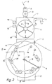
- the thread support elements 32, 33 together form a thread support for an additional thread reserve. They are each designed in the form of cylindrical rollers which carry a thread receiving or guiding groove 350 which is V-shaped in cross section on the circumference.
- the outer thread support elements 32 are arranged in a rotationally fixed manner on the carrier disk 30, while the radially inner thread support elements 33 are rotatably mounted on bearing bolts 36 arranged on the carrier disk 30 above.
- all the thread support elements 32, 33 could either be held in a rotationally fixed manner or rotatably mounted.
- the length of the bearing bolts 36 is chosen such that with two thread support elements 32, 33 assigned to each other in pairs, the radially inner thread support element 33 stands axially next to the thread support element 32, as can be seen from FIG. 3.
- the thread guide arm 16 is angled such that it can freely overlap the protruding thread support elements 32, 33; his eyelet 14 lies with their inner edge within the axial extent, ie within the V-shaped groove 350 of the radially outer thread support elements 32, the eyelet 14 being movable even at a small radial distance from these thread support elements 32.
- the thread support elements 33 which are located radially on the inside with respect to the axis 15, lie with the apex of their V-shaped groove 350 in a common vertical plane which runs either through the axis of the fixed eyelet 11 or at a small lateral distance from it.
- This configuration of the arrangement of the thread support elements 32, 33 ensures that when the thread guide arm 16 swivels counterclockwise from the operating position shown in FIG. 1 into the return position of the thread 12 shown in FIG. 2 on the thread path between the thread wheel that is then stationary 4 and the fixed second thread eyelet 11 is placed on the thread support elements 32, 33 arranged at equal angular intervals, forming an additional thread reserve.
- the additional thread reserve thus formed is simply released by pulling thread through the thread eyelet 11, with the result that, starting from the position shown in FIG. 2, the thread guide arm 16 rotates clockwise and the thread continuously from the thread support elements 32 , 33 is lifted until the operating position according to FIG. 1 is reached, in which the thread wheel 4 delivers thread again.
- the thread guide arm 16 with the coupled DC motor 18 and the first signal transmitter 19 serving as a measuring transducer are part of a regulator which regulates the thread tension on the outlet side of the thread wheel 4 to a constant value predetermined by the torque of the DC motor 18.
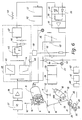
- Control circuit 39 fed in which processes the signal and on the output side generates a frequency signal of a specific pulse repetition frequency, which is indicated at 40 and is fed to control electronics 41, which feeds a control signal in the form of a corresponding step pulse sequence to the stepping motor 3 via a downstream power output stage 42.
- the low-pass filter 37 filters out higher-frequency interference signals from the analog signal coming from the signal transmitter 19; on the output side, the voltage follower 38 supplies a signal voltage potential which has a relatively low output impedance and which is dependent on the respective angular position of the thread guide arm 16.
- This voltage potential is applied to a circuit arrangement of the circuit part 39 which essentially consists of two integrators 43, 44 and which has a time constant which is matched to the respective starting or stopping characteristics of the stepping motor and thus the temporal change in the frequency of the frequency signal 40 during startup or of the outlet of the stepping motor 3 is limited in such a way that the stepping motor 3 loaded by the thread 12 and the thread wheel 4 etc. can follow the frequency change.
- the thread consumer can cover his thread requirement from the thread reserve, the thread tension and the torque of the direct current motor 18 which is independent of the setting angle and which specifies the target value always being kept at its target value.
- the stepping motor 3 can adjust the thread wheel to the thread speed required during this time Accelerate speed within a time, the length of which is determined by the start-up characteristic and which ensures that the stepper motor remains in step with the frequency signal 40.
- the integrator 43 limits the speed of the frequency change when the stepping motor 3 starts up, while the integrator 44 limits the speed of the frequency change to a value which is below the stopping characteristic of the stepping motor 3, so that it stops exactly the frequency change of the frequency signal 40 until it stops follows.
- the circuit arrangement formed by the integrators 36, 37 is followed by a diode path 45, the output of which is connected via a low-pass filter 46 to a voltage / frequency converter 47 which supplies the frequency signal 40.
- the diode path 45 forms a threshold circuit which prevents the voltage / frequency converter 47 from being supplied with signal voltages below a lower threshold value, which would result in a frequency signal with an impermissibly low frequency being output for the stepping motor 3.
- the low-pass filter 46 prevents malfunctions of the voltage / frequency converter 47, which is designed on the output side with a zero point suppression and which has a characteristic curve that can be changed in order to adjust the angular position of the thread guide arm 16 and thus the size of the thread reserve for a specific stationary thread running speed accordingly can.
- the analog output from the voltage follower 38 The voltage signal is also fed via a potentiometer 48 to a differentiator 49, where it is differentiated.
- the output of the differentiating element 49 is connected via an adder 50 and a voltage follower 51 to a second potentiometer 52, which makes it possible to set the magnitude of the torque exerted by the direct current motor 18 and thus the nominal value of the thread tension.
- the control input of a constant current source 53 is connected to the potentiometer 45 and excites the direct current motor 18 with constant current via a power output stage 54.
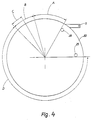
- the thread guide arm 16 moves in the work area designated by A in FIG. 4, which in the selected embodiment extends over an angular range of approximately 45 ° and clockwise through the stop pin 28 and counterclockwise through a so-called
- the storage area B is limited by approximately 30 ° here, which is characterized in that when the thread guide arm 16 assumes a position ("limit position") lying within the storage area B, ie immersed in the storage area B, the stepper motor 3 is stopped.
- the thread guide arm 16 begins to migrate from its desired angular position corresponding to the respective thread speed, so that the analog voltage signal fed to the switching part 39 undergoes a corresponding change.
- the corresponding pulse control signal 40 for the stepper motor 3 generated in the circuit part 39 is accordingly changed in the sense that the stepper motor 3 changes its speed and thus also the thread delivery speed until a steady state is reached again, in which the thread guide arm 16 assumes a fixed angular position in which the thread pulling force exerted by the thread via the eyelet 14 on the thread guide arm 15 keeps the torque exerted by the direct current motor 18 in equilibrium.
- the controller has an integrating effect.
- the damping acting on the thread guide arm 16, which is essentially proportional to its angular velocity during a pivoting movement, is generated either by the DC motor 18, which has a correspondingly low internal resistance, or by its own damping device of a known type, not shown.
- an external signal source for example one Central control device for all or for a certain number of thread delivery devices of a circular knitting machine
- the control input of the constant current source 53 is fed via the potentiometer 52, an external control signal which allows remote adjustment of the torque of the DC motor 18 and thus the thread tension.
- Measuring sockets 56, 57 allow a speed signal which is proportional to the step frequency of the step motor 3 and which characterizes the speed of the step motor and a signal which indicates the input voltage of the constant current source 53 and thus the constant current feeding the direct current motor 18 and thus the torque emitted by the direct current motor to be removed and fed to an external display source, which allows an immediate reading and control of the thread running speed (thread quantity per unit time) and the thread tension.
- the differentiator 49 supplies a compensation signal, the size of which is set via the potentiometer 48 and which is added to the actuating signal of the DC motor 18 via the adder 50. It has the effect that, in particular in the case of small thread tension settings, the excitation of the direct current motor 18 is additionally increased or decreased temporarily in the sense of reducing this control deviation when a control deviation occurs.
- the electronics 58 act in such a way that the potential at the control input of the constant current source 53 is lowered by a predetermined, possibly adjustable value, and the thread guide arm 16 enters a partial area C of reduced thread tension within the storage area B.
- the purpose of this measure is as follows:
- the thread guide arm 16 penetrates into the storage area B with its inherent inertia until the stepping motor 3 has come to a standstill and the thread is tensioned again and thus preventing the further movement of the thread guide arm 16.
- the exact position or depth of penetration that the thread guide arm reaches in the storage area B depends, among other things, on the thread speed and thread tension and how quickly the thread take-up was interrupted. If the thread guide arm 16 remains in the part B -C of the storage area B adjoining the work area A, the thread tension remains at the setpoint set by the potentiometer 52, which also applies to the knitting operation, when the stepping motor 3 is stopped.
- the knitting machine is now unable to hold the thread under this thread tension because, for example, the thread clamp of the striping apparatus gives way slightly, the will move Thread guide lever 16 under the effect of the setpoint biasing force exerted by the DC motor 18 slowly, with reference to FIG. 1.4, to the left.
- the electronics 58 automatically reduces the thread tension by a corresponding reduction in the excitation of the DC motor 18 to a much smaller value, which is so small that the tensile force exerted by the thread is harmless .
- the thread tension is not zero, because otherwise the thread breaker would respond.
- the thread tension in the area of the movement of the thread guide arm 16 comprising the working area A and part of the storage area B is constant and equal to the desired value; it is lowered only in the sub-area C of the storage area B.
- the thread delivery device described so far supplies the thread with constant thread tension to the thread consumer with continuous thread consumption even at different thread speeds, the thread guide arm 16 moving in the working area A (FIG. 4). If the thread consumption is interrupted, for example when the machine is at a standstill or when the thread is laid out in a knitting machine working with a striping apparatus, the thread guide arm 16, as already explained, enters the storage area B, in which the stepping motor is stopped and the thread going to the thread consumer first below the normal setpoint thread tension is held. If, under the effect of this thread tension, the thread is withdrawn somewhat and the thread guide arm thus enters area C of reduced thread tension, the thread tension is reduced to a small value, as has also already been explained.
- the thread delivery device is used for a flat knitting machine or a circular knitting machine (sock or hosiery machine) working in a pendulum way
- the slide or the needle cylinder begins its return movement after reaching the reversal point of movement, because of the shortening of the thread travel path from the fixed outlet thread eyelet 11 to the thread guide practically first returned thread.
- the thread return decreases, so that the thread guide arm 16 is moved counterclockwise under the effect of the torque exerted by the direct current motor 18, in relation to FIG. 4, and thereby in FIG. 4 marked with D occurs further movement range, which can also be referred to as "thread return range".
- Electronics 58 were previously switched off by a manually operated switch 60 (Fig. 1, 6).
- the dimming disk 26 assigned to the first signal transmitter 19 can also be designed such that when the thread guide arm 16 reaches a certain position within the storage area B, it controls the phototransistor 23 in such a way that it no longer delivers an analog signal causing the electronics 58 to respond.
- the second signal transmitter 20 acting as a position transmitter becomes effective, the photo transistor 24 of which emits a signal which characterizes the angular position of the thread guide arm 16.
- This signal is fed to a voltage follower 61 via a low-pass filter 60 which filters out disturbances, which is followed by an electronic thread tension increasing circuit 62 which, via a diode 63 and an adding circuit indicated by a resistor 64, applies an increased potential to the control input of the constant current source 53.
- the torque exerted by the direct current motor 18 is increased, with the result that the thread guide arm 16 pulls back the thread coming back from the thread consumer through the thread eyelet 11 with increased tensile force and in the course of its counter-clockwise rotational movement in relation to FIG. 1 described way on the thread support elements 32, 33.
- the movement of the thread guide arm 16 comes to a standstill as soon as the entire thread which has been retrieved is introduced into the additional thread reserve. Should the additional thread reserve to accommodate the Returned thread is not sufficient or if there is a thread break, the thread guide arm 16 finally comes to rest on the stop pin 29, the associated switching means of which are actuated, thus emitting the shutdown signal.
- the electronic circuit parts 60, 61, 62 are illustrated in detail in FIG. 7:
- a voltage follower 61 designed in the form of an IC (LM 324), the output of which is connected via a resistor and a capacitor 67 with a differentiating element 68, to the emitter of the phototransistor 24 via a low-pass filter 60 formed by a capacitor 64 and a resistor 65 is connected, which has a capacitor 69 and a resistor 70 and a diode 71 which is connected to a voltage divider formed by two resistors 72, 73.
- a comparator 74 formed by an IC (LM 324), which is connected via a diode 75 and a monoflop 76 (IC LM 324) to the input of an amplifier 77 (IC LM 324).
- the output of the amplifier 27 is connected via a potentiometer 78 and the diode 63 and the adder 64 to the control input 79 of the constant current source 53.
- the second signal generator 20 indicates by the analog signal emitted by the phototransistor 24 that the thread guide arm 16 has entered the return area D, this analog signal is amplified in the voltage follower 61 and then differentiated in the differentiator 68.
- the differentiator 68 in turn emits a signal only as long as the thread guide lever 16 is in motion, specifically counterclockwise with respect to FIG. 1.
- the change in time of the analog signal required for this is achieved by the special shape of the track or edge of the anti-glare plate 27 scanned by the light barrier 22, 24.
- the downstream comparator 74 integrates the signal emitted by the differentiator 68 and passes this information on to the monoflop 76 in the form of a constant positive voltage level.
- a positive potential appears which is amplified by the amplifier 77 and applied to the control input 79 of the constant current source 53 via the setting potentiometer 78 and the adder 64.
- the potentiometer 78 makes it possible to set the thread tension increase required in each case for the return of the thread.
- the arrangement can be simplified to simplify the construction also be such that only a single cover plate 80 (FIG. 5) is provided, which carries the traces scanned by the two light barriers 21, 23 and 22, 24 on different radii, as illustrated in FIG. 5.
- the essentially eccentric track 26a formed by the outer peripheral edge corresponds to that of the cover disk 26 of the first signal transmitter 19, while the inner track 27a is designed according to that of the anti-mask disk 27 of the second signal transmitter 20.
- the radially inner track 27a Since it would be difficult for constructional reasons to produce the radially inner track 27a continuously over its entire circumferential area without connection to the radially outer disk areas, it is composed of individual eccentric sections 27b, which at 81 each with the radially outer surrounding disk material via a radial shoulder or an acute-angled transition are connected.
- the monoflop 76 for example set to 10 ms, now prevents a brief interruption of the signal flow due to the small anti-glare areas at 81 when the anti-glare disk 80 transitions from one eccentric track 27b to the next following one when the thread guide arm 16 moves.
- This division of the track 27a into successive eccentric functions also enables a relatively large voltage increase per unit time of the analog signal to be achieved when the shield 80 rotates, so that the differential quotient (dU / dt) generated by the differentiator 68 also has a size which is sufficient for the functional reliability.
Landscapes
- Engineering & Computer Science (AREA)
- Textile Engineering (AREA)
- Knitting Machines (AREA)
- Looms (AREA)
Applications Claiming Priority (2)
| Application Number | Priority Date | Filing Date | Title |
|---|---|---|---|
| DE3732102 | 1987-09-24 | ||
| DE3732102A DE3732102C1 (de) | 1987-09-24 | 1987-09-24 | Fadenliefervorrichtung fuer Textilmaschinen mit zeitlich unterschiedlichem Fadenverbrauch,insbesondere Strick- und Wirkmaschinen |
Publications (2)
| Publication Number | Publication Date |
|---|---|
| EP0308609A2 true EP0308609A2 (fr) | 1989-03-29 |
| EP0308609A3 EP0308609A3 (fr) | 1991-07-03 |
Family
ID=6336726
Family Applications (1)
| Application Number | Title | Priority Date | Filing Date |
|---|---|---|---|
| EP19880111566 Withdrawn EP0308609A3 (fr) | 1987-09-24 | 1988-07-19 | Dispositif d'alimentation du fil pour des machines textiles à consommation de fil temporairement différent, notamment our des machines à tricoter |
Country Status (9)
| Country | Link |
|---|---|
| US (1) | US4829790A (fr) |
| EP (1) | EP0308609A3 (fr) |
| JP (1) | JPH07109047B2 (fr) |
| KR (1) | KR910005011B1 (fr) |
| CN (1) | CN1008751B (fr) |
| CS (1) | CS271348B2 (fr) |
| DD (1) | DD282482A5 (fr) |
| DE (1) | DE3732102C1 (fr) |
| PT (1) | PT88583A (fr) |
Cited By (4)
| Publication number | Priority date | Publication date | Assignee | Title |
|---|---|---|---|---|
| DE102006038339A1 (de) * | 2006-08-15 | 2008-02-21 | Andritz Küsters GmbH & Co. KG | Verfahren und Vorrichtung zur Ausrüstung einer Warenbahn |
| EP2441868A4 (fr) * | 2009-06-09 | 2014-06-04 | Shima Seiki Mfg | Dispositif d'alimentation en fil et procédé d'alimentation en fil pour machine à tricoter |
| CN109183264A (zh) * | 2018-11-14 | 2019-01-11 | 慈溪市赛美格针织器材有限公司 | 一种结构改进型输纱器 |
| US11399885B2 (en) | 2014-10-31 | 2022-08-02 | Medtronic Advanced Energy Llc | Power monitoring circuitry and method for reducing leakage current in RF generators |
Families Citing this family (20)
| Publication number | Priority date | Publication date | Assignee | Title |
|---|---|---|---|---|
| DE3824034C1 (fr) * | 1988-07-15 | 1989-09-14 | Gustav 7290 Freudenstadt De Memminger | |
| JPH0735227B2 (ja) * | 1988-11-25 | 1995-04-19 | 三田工業株式会社 | 再給紙装置 |
| JP2892392B2 (ja) * | 1989-08-31 | 1999-05-17 | 株式会社福原精機製作所 | 編機のステッチ自動調整装置および方法 |
| DE4131322A1 (de) * | 1991-09-20 | 1993-03-25 | Stoll & Co H | Fadenliefervorrichtung |
| IT1254721B (it) * | 1992-03-17 | 1995-10-09 | Angelo Paggiaro | Apparecchiatura automatica per la visualizzazione e il controllo centralizzato di una molteplicita' di anomalie particolarmente in alimentatori per macchine di maglieria e per macchinari tessili in genere |
| GB9306009D0 (en) * | 1993-03-23 | 1993-05-12 | Ncr Int Inc | Sheet handing apparatus |
| US5505067A (en) * | 1994-07-06 | 1996-04-09 | Waddington Electronics, Inc. | Non-contact double-block speed controller |
| GB2297331A (en) * | 1995-01-24 | 1996-07-31 | Cobble Blackburn Ltd | Yarn feed arrangement for tufting machine |
| DE19537325C1 (de) * | 1995-10-06 | 1996-11-28 | Memminger Iro Gmbh | Fadenliefergerät mit elektronischer Ansteuerung |
| GB0318271D0 (en) * | 2003-08-05 | 2003-09-10 | Univ Manchester | Improved knitting machines and methods of knitting |
| JP4015984B2 (ja) * | 2003-10-17 | 2007-11-28 | 株式会社島精機製作所 | 横編機の糸供給装置 |
| DE102004017045B3 (de) * | 2004-04-02 | 2005-12-08 | Memminger-Iro Gmbh | Vorrichtung und Verfahren zur Fadenpositivlieferung |
| DE102004051520B4 (de) * | 2004-10-21 | 2014-12-31 | Memminger-Iro Gmbh | Fadenliefergerät mit Rückholbetrieb und Verfahren zum Betrieb eines Fadenliefergerätes |
| ITFI20060335A1 (it) * | 2006-12-22 | 2008-06-23 | Giovanni Corsani | Un dispositivo alimentatore e recuperatore del filo per macchine tessili |
| CN105714468B (zh) * | 2016-04-22 | 2019-04-16 | 浙江鹏飞针织有限公司 | 一种高可靠性袜机 |
| KR102601459B1 (ko) * | 2018-01-26 | 2023-11-14 | 도레이 카부시키가이샤 | 기포, 제트룸 및 기포의 제조 방법 |
| JP7048407B2 (ja) * | 2018-05-11 | 2022-04-05 | 株式会社島精機製作所 | 編機の張力測定装置及びその張力測定方法 |
| CN110541236B (zh) * | 2019-08-31 | 2020-12-29 | 嘉兴科禾能源科技有限公司 | 一种帆布生产用同步进线且带有提醒的设备 |
| US12276052B2 (en) | 2021-12-22 | 2025-04-15 | Nike, Inc. | Tensioning device |
| CN114277499A (zh) * | 2021-12-27 | 2022-04-05 | 青岛即发集团股份有限公司 | 一种转速可调积极型输纱器 |
Family Cites Families (11)
| Publication number | Priority date | Publication date | Assignee | Title |
|---|---|---|---|---|
| US3858416A (en) * | 1973-07-23 | 1975-01-07 | Eugene F White | Knitting machine yarn feeding apparatus |
| FR2264904B1 (fr) * | 1974-03-21 | 1977-08-19 | Inst Textile De France | |
| GB2125072B (en) * | 1982-08-07 | 1986-08-13 | Geoffrey Edmund Whellams | Self-adjusting filament tensioner |
| FR2538419A1 (fr) * | 1982-12-28 | 1984-06-29 | Inst Textile De France | Dispositif de regulation de la longueur de fil absorbee par un metier a tricoter |
| US4632324A (en) * | 1982-11-12 | 1986-12-30 | Mayer & Cie. Gmbh & Co. | Strand storing and delivering device |
| DE3416195C2 (de) * | 1984-05-02 | 1987-01-08 | Gustav 7290 Freudenstadt Memminger | Fadenliefervorrichtung für fadenverarbeitende Textilmaschinen, bspw. Rundstrick- oder -wirkmaschinen |
| DE3429207C2 (de) * | 1984-08-08 | 1986-06-19 | Gustav 7290 Freudenstadt Memminger | Fadenliefervorrichtung für fadenverbrauchende Textilmaschinen |
| DE3431743C2 (de) * | 1984-08-29 | 1986-11-27 | Christian Montopoli Val d'Arno Bretscher | Vorrichtung zur Fadenzuführung für eine Strickmaschine |
| SE8502436D0 (sv) * | 1985-05-17 | 1985-05-17 | Iro Ab | Anordning for positiv matning av ett foretredesvis elastiskt garn vid en stickmaskin, foretredesvis en strumpstickmaskin |
| DE3702702A1 (de) * | 1986-02-27 | 1987-09-03 | Baer Maschf Josef | Regeleinrichtung fuer die fadenspannung bei wickelmaschinen, insbesondere in der faserwickeltechnik |
| DE3627731C1 (de) * | 1986-08-16 | 1988-03-31 | Gustav Memminger | Fadenliefervorrichtung mit elektronischer Fadenspannungsregelung |
-
1987
- 1987-09-24 DE DE3732102A patent/DE3732102C1/de not_active Expired
-
1988
- 1988-07-19 EP EP19880111566 patent/EP0308609A3/fr not_active Withdrawn
- 1988-09-07 US US07/241,303 patent/US4829790A/en not_active Expired - Fee Related
- 1988-09-10 CN CN88106634A patent/CN1008751B/zh not_active Expired
- 1988-09-20 DD DD88319968A patent/DD282482A5/de not_active IP Right Cessation
- 1988-09-23 CS CS886316A patent/CS271348B2/cs unknown
- 1988-09-23 PT PT88583A patent/PT88583A/pt not_active Application Discontinuation
- 1988-09-24 KR KR1019880012402A patent/KR910005011B1/ko not_active Expired
- 1988-09-24 JP JP63237551A patent/JPH07109047B2/ja not_active Expired - Lifetime
Cited By (6)
| Publication number | Priority date | Publication date | Assignee | Title |
|---|---|---|---|---|
| DE102006038339A1 (de) * | 2006-08-15 | 2008-02-21 | Andritz Küsters GmbH & Co. KG | Verfahren und Vorrichtung zur Ausrüstung einer Warenbahn |
| DE102006038339B4 (de) * | 2006-08-15 | 2008-08-21 | Andritz Küsters GmbH & Co. KG | Verfahren und Vorrichtung zur Ausrüstung einer Warenbahn |
| EP2441868A4 (fr) * | 2009-06-09 | 2014-06-04 | Shima Seiki Mfg | Dispositif d'alimentation en fil et procédé d'alimentation en fil pour machine à tricoter |
| US11399885B2 (en) | 2014-10-31 | 2022-08-02 | Medtronic Advanced Energy Llc | Power monitoring circuitry and method for reducing leakage current in RF generators |
| CN109183264A (zh) * | 2018-11-14 | 2019-01-11 | 慈溪市赛美格针织器材有限公司 | 一种结构改进型输纱器 |
| CN109183264B (zh) * | 2018-11-14 | 2023-08-25 | 慈溪市赛美格自动化科技有限公司 | 一种结构改进型输纱器 |
Also Published As
| Publication number | Publication date |
|---|---|
| CN1008751B (zh) | 1990-07-11 |
| JPH07109047B2 (ja) | 1995-11-22 |
| DD282482A5 (de) | 1990-09-12 |
| CN1032202A (zh) | 1989-04-05 |
| CS631688A2 (en) | 1989-11-14 |
| KR910005011B1 (ko) | 1991-07-20 |
| JPH0197246A (ja) | 1989-04-14 |
| PT88583A (pt) | 1989-07-31 |
| US4829790A (en) | 1989-05-16 |
| EP0308609A3 (fr) | 1991-07-03 |
| KR890005324A (ko) | 1989-05-13 |
| DE3732102C1 (de) | 1989-05-03 |
| CS271348B2 (en) | 1990-09-12 |
Similar Documents
| Publication | Publication Date | Title |
|---|---|---|
| EP0308609A2 (fr) | Dispositif d'alimentation du fil pour des machines textiles à consommation de fil temporairement différent, notamment our des machines à tricoter | |
| EP0256519B1 (fr) | Dispositif fournisseur de fil avec réglage électronique de la tension du fil | |
| DE19537325C1 (de) | Fadenliefergerät mit elektronischer Ansteuerung | |
| DE3416195C2 (de) | Fadenliefervorrichtung für fadenverarbeitende Textilmaschinen, bspw. Rundstrick- oder -wirkmaschinen | |
| DE2715988C2 (de) | Vorrichtung zum Steuern des Bandauftrages bei einer Schärmaschine | |
| EP0240799B1 (fr) | Procédé et dispositif pour régler la longueur et les mailles d'articles tricotés | |
| DE2736416A1 (de) | Verfahren und vorrichtung fuer die steuerung von strickmaschinen | |
| DE3024095A1 (de) | Wickelmaschine zum aufwickeln von strangfoermigem wickelgut auf eine spule | |
| DE2642183C2 (de) | Fadenliefervorrichtung, insbesondere für Strickmaschinen | |
| DE4032402C2 (fr) | ||
| EP0658507A1 (fr) | Procédé pour détecter une réserve de fil dans un dispositif pour emmagasiner et délivrer le fil, et dispositif pour emmagasiner et délivrer le fil | |
| EP0943571B1 (fr) | Fournisseur de fil avec une voie de fil ameliorée | |
| DE4116497B4 (de) | Fadenliefervorrichtung | |
| DE60001527T2 (de) | Vorrichtung zur Fadenbruchfeststellung in einer Nähmaschine | |
| DE3731379C2 (fr) | ||
| DE69611723T2 (de) | Vorrichtung zum regeln der drehgeschwindigkeit einer antriebseinheit für eine fadenwickel- und speichertrommel | |
| DE2635200C2 (de) | Fadenzuführeinrichtung | |
| EP0217373B1 (fr) | Dispositif d'alimentation de fil pour machines textiles | |
| DE2550612B2 (de) | Wickelmaschine | |
| DE19637556C1 (de) | Fadenliefervorrichtung | |
| DE3147163C2 (de) | Vorrichtung zur Fadenzuführung zum Maschenbildungssystem einer Wirkmaschine | |
| DE102017203161B4 (de) | Flechtmaschine | |
| DE19635373C2 (de) | Vorrichtung zum Ausgleichen von Fadenverbrauchs- und Fadenspannungsschwankungen bei der Zuführung von fadenförmigem Material | |
| DE3116683A1 (de) | Verfahren und vorrichtung zur laengenmessung textiler faeden | |
| DE2639207A1 (de) | Fadenliefervorrichtung |
Legal Events
| Date | Code | Title | Description |
|---|---|---|---|
| PUAI | Public reference made under article 153(3) epc to a published international application that has entered the european phase |
Free format text: ORIGINAL CODE: 0009012 |
|
| AK | Designated contracting states |
Kind code of ref document: A2 Designated state(s): DE ES FR GB IT |
|
| RAP1 | Party data changed (applicant data changed or rights of an application transferred) |
Owner name: MEMMINGER-IRO GMBH |
|
| PUAL | Search report despatched |
Free format text: ORIGINAL CODE: 0009013 |
|
| AK | Designated contracting states |
Kind code of ref document: A3 Designated state(s): DE ES FR GB IT |
|
| RHK1 | Main classification (correction) |
Ipc: D04B 15/48 |
|
| RAP1 | Party data changed (applicant data changed or rights of an application transferred) |
Owner name: MEMMINGER-IRO GMBH |
|
| RAP3 | Party data changed (applicant data changed or rights of an application transferred) |
Owner name: MEMMINGER-IRO GMBH |
|
| STAA | Information on the status of an ep patent application or granted ep patent |
Free format text: STATUS: THE APPLICATION IS DEEMED TO BE WITHDRAWN |
|
| 18D | Application deemed to be withdrawn |
Effective date: 19920704 |