EP0308761B1 - Bauteil für den Stromanschluss einer Batterie aus elektrochemischen Zellen - Google Patents
Bauteil für den Stromanschluss einer Batterie aus elektrochemischen Zellen Download PDFInfo
- Publication number
- EP0308761B1 EP0308761B1 EP88114890A EP88114890A EP0308761B1 EP 0308761 B1 EP0308761 B1 EP 0308761B1 EP 88114890 A EP88114890 A EP 88114890A EP 88114890 A EP88114890 A EP 88114890A EP 0308761 B1 EP0308761 B1 EP 0308761B1
- Authority
- EP
- European Patent Office
- Prior art keywords
- battery
- pressure
- metal plate
- contact
- power connection
- Prior art date
- Legal status (The legal status is an assumption and is not a legal conclusion. Google has not performed a legal analysis and makes no representation as to the accuracy of the status listed.)
- Expired - Lifetime
Links
- 229910052751 metal Inorganic materials 0.000 claims description 16
- 239000002184 metal Substances 0.000 claims description 16
- RYGMFSIKBFXOCR-UHFFFAOYSA-N Copper Chemical compound [Cu] RYGMFSIKBFXOCR-UHFFFAOYSA-N 0.000 claims description 3
- 229910052802 copper Inorganic materials 0.000 claims description 3
- 239000010949 copper Substances 0.000 claims description 3
- 239000000446 fuel Substances 0.000 claims description 2
- 239000000126 substance Substances 0.000 claims 1
- KWYUFKZDYYNOTN-UHFFFAOYSA-M Potassium hydroxide Chemical compound [OH-].[K+] KWYUFKZDYYNOTN-UHFFFAOYSA-M 0.000 description 3
- 229920001971 elastomer Polymers 0.000 description 3
- 239000000806 elastomer Substances 0.000 description 3
- 239000007789 gas Substances 0.000 description 3
- 239000000463 material Substances 0.000 description 3
- PXHVJJICTQNCMI-UHFFFAOYSA-N Nickel Chemical compound [Ni] PXHVJJICTQNCMI-UHFFFAOYSA-N 0.000 description 2
- 238000004519 manufacturing process Methods 0.000 description 2
- 238000009423 ventilation Methods 0.000 description 2
- UFHFLCQGNIYNRP-UHFFFAOYSA-N Hydrogen Chemical compound [H][H] UFHFLCQGNIYNRP-UHFFFAOYSA-N 0.000 description 1
- 239000000853 adhesive Substances 0.000 description 1
- 238000004026 adhesive bonding Methods 0.000 description 1
- 230000001070 adhesive effect Effects 0.000 description 1
- QVGXLLKOCUKJST-UHFFFAOYSA-N atomic oxygen Chemical compound [O] QVGXLLKOCUKJST-UHFFFAOYSA-N 0.000 description 1
- 239000003054 catalyst Substances 0.000 description 1
- 238000010276 construction Methods 0.000 description 1
- 239000003792 electrolyte Substances 0.000 description 1
- 238000005516 engineering process Methods 0.000 description 1
- 239000012530 fluid Substances 0.000 description 1
- 239000001257 hydrogen Substances 0.000 description 1
- 229910052739 hydrogen Inorganic materials 0.000 description 1
- 238000000034 method Methods 0.000 description 1
- 229910052759 nickel Inorganic materials 0.000 description 1
- IJGRMHOSHXDMSA-UHFFFAOYSA-N nitrogen Substances N#N IJGRMHOSHXDMSA-UHFFFAOYSA-N 0.000 description 1
- 229910052757 nitrogen Inorganic materials 0.000 description 1
- QJGQUHMNIGDVPM-UHFFFAOYSA-N nitrogen group Chemical group [N] QJGQUHMNIGDVPM-UHFFFAOYSA-N 0.000 description 1
- 239000001301 oxygen Substances 0.000 description 1
- 229910052760 oxygen Inorganic materials 0.000 description 1
- 239000000376 reactant Substances 0.000 description 1
- 238000007789 sealing Methods 0.000 description 1
- 230000035882 stress Effects 0.000 description 1
- 230000008646 thermal stress Effects 0.000 description 1
Images
Classifications
-
- H—ELECTRICITY
- H01—ELECTRIC ELEMENTS
- H01M—PROCESSES OR MEANS, e.g. BATTERIES, FOR THE DIRECT CONVERSION OF CHEMICAL ENERGY INTO ELECTRICAL ENERGY
- H01M8/00—Fuel cells; Manufacture thereof
- H01M8/02—Details
- H01M8/0202—Collectors; Separators, e.g. bipolar separators; Interconnectors
- H01M8/0204—Non-porous and characterised by the material
- H01M8/0206—Metals or alloys
-
- C—CHEMISTRY; METALLURGY
- C25—ELECTROLYTIC OR ELECTROPHORETIC PROCESSES; APPARATUS THEREFOR
- C25B—ELECTROLYTIC OR ELECTROPHORETIC PROCESSES FOR THE PRODUCTION OF COMPOUNDS OR NON-METALS; APPARATUS THEREFOR
- C25B9/00—Cells or assemblies of cells; Constructional parts of cells; Assemblies of constructional parts, e.g. electrode-diaphragm assemblies; Process-related cell features
- C25B9/60—Constructional parts of cells
- C25B9/65—Means for supplying current; Electrode connections; Electric inter-cell connections
-
- H—ELECTRICITY
- H01—ELECTRIC ELEMENTS
- H01M—PROCESSES OR MEANS, e.g. BATTERIES, FOR THE DIRECT CONVERSION OF CHEMICAL ENERGY INTO ELECTRICAL ENERGY
- H01M8/00—Fuel cells; Manufacture thereof
- H01M8/02—Details
- H01M8/0202—Collectors; Separators, e.g. bipolar separators; Interconnectors
- H01M8/0247—Collectors; Separators, e.g. bipolar separators; Interconnectors characterised by the form
- H01M8/0254—Collectors; Separators, e.g. bipolar separators; Interconnectors characterised by the form corrugated or undulated
-
- H—ELECTRICITY
- H01—ELECTRIC ELEMENTS
- H01M—PROCESSES OR MEANS, e.g. BATTERIES, FOR THE DIRECT CONVERSION OF CHEMICAL ENERGY INTO ELECTRICAL ENERGY
- H01M8/00—Fuel cells; Manufacture thereof
- H01M8/24—Grouping of fuel cells, e.g. stacking of fuel cells
- H01M8/2465—Details of groupings of fuel cells
- H01M8/247—Arrangements for tightening a stack, for accommodation of a stack in a tank or for assembling different tanks
-
- H—ELECTRICITY
- H01—ELECTRIC ELEMENTS
- H01M—PROCESSES OR MEANS, e.g. BATTERIES, FOR THE DIRECT CONVERSION OF CHEMICAL ENERGY INTO ELECTRICAL ENERGY
- H01M8/00—Fuel cells; Manufacture thereof
- H01M8/02—Details
- H01M8/0202—Collectors; Separators, e.g. bipolar separators; Interconnectors
- H01M8/0204—Non-porous and characterised by the material
- H01M8/0223—Composites
- H01M8/0228—Composites in the form of layered or coated products
-
- Y—GENERAL TAGGING OF NEW TECHNOLOGICAL DEVELOPMENTS; GENERAL TAGGING OF CROSS-SECTIONAL TECHNOLOGIES SPANNING OVER SEVERAL SECTIONS OF THE IPC; TECHNICAL SUBJECTS COVERED BY FORMER USPC CROSS-REFERENCE ART COLLECTIONS [XRACs] AND DIGESTS
- Y02—TECHNOLOGIES OR APPLICATIONS FOR MITIGATION OR ADAPTATION AGAINST CLIMATE CHANGE
- Y02E—REDUCTION OF GREENHOUSE GAS [GHG] EMISSIONS, RELATED TO ENERGY GENERATION, TRANSMISSION OR DISTRIBUTION
- Y02E60/00—Enabling technologies; Technologies with a potential or indirect contribution to GHG emissions mitigation
- Y02E60/30—Hydrogen technology
- Y02E60/50—Fuel cells
-
- Y—GENERAL TAGGING OF NEW TECHNOLOGICAL DEVELOPMENTS; GENERAL TAGGING OF CROSS-SECTIONAL TECHNOLOGIES SPANNING OVER SEVERAL SECTIONS OF THE IPC; TECHNICAL SUBJECTS COVERED BY FORMER USPC CROSS-REFERENCE ART COLLECTIONS [XRACs] AND DIGESTS
- Y10—TECHNICAL SUBJECTS COVERED BY FORMER USPC
- Y10T—TECHNICAL SUBJECTS COVERED BY FORMER US CLASSIFICATION
- Y10T428/00—Stock material or miscellaneous articles
- Y10T428/12—All metal or with adjacent metals
- Y10T428/12493—Composite; i.e., plural, adjacent, spatially distinct metal components [e.g., layers, joint, etc.]
- Y10T428/12535—Composite; i.e., plural, adjacent, spatially distinct metal components [e.g., layers, joint, etc.] with additional, spatially distinct nonmetal component
- Y10T428/12556—Organic component
- Y10T428/12562—Elastomer
Definitions
- the invention relates to a component for the power connection of a battery made of electrochemical cells, in particular fuel elements, with pressure pads in the form of metallic contact bodies each having two contact plates.
- a battery of the type mentioned with pressure pads in the form of metallic contact bodies is known from DE-PS 27 29 640.
- the contact bodies serve on the one hand to draw current, on the other hand they have a cavity to which a medium under pressure can be supplied so that a uniform contact pressure is exerted on the catalyst material of the neighboring cells.
- the electrochemical cells of such a battery are stacked on top of one another in a bipolar manner, with a pressure plate being located at the end of the stack.
- a metal plate between the pressure plates and the pressure pad of the nearest cell, which has an outwardly projecting tab, i.e. a so-called pole plate.
- pole plates are used for power consumption or for power connection.
- the electrical contact between the pole plates and the pressure pads is established in such a way that a pressure is applied to the cavity of the pressure pads, for example by means of a gas.
- the electrical contact only comes about when the cell stack, ie the battery, is operated at atmospheric pressure or at an ambient pressure that is (significantly) lower than the pressure inside the pressure pad.
- the ambient pressure is above the pressure or if it rises above the pressure, the current flow is either interrupted or the pressure pad is partially overloaded due to undefined contact areas. This jeopardizes the functional reliability of the battery or battery modules.
- the object of the invention is to provide a component for the power connection of a battery of the type mentioned - with two contact plates each having contact bodies - which also allows the battery to operate at elevated ambient pressure, with the simultaneous use of pressure pads for isostatic contact pressure generation, and further a parallel connection of cells or cell groups (within the cell stack) enables.
- a metal plate is welded all around between the two contact plates of each contact body, in that the metal plate has an outwardly projecting metallic tab, and in that the metal plate is provided with an elastomer on the edge.
- the pole plate is integrated in the pressure pad. This brings both functional and manufacturing advantages, i.e. such a component is relatively easy to implement in terms of production technology. In addition, all of the above-mentioned problems are eliminated when the component according to the invention is used.
- Advantageous embodiments of the component according to the invention consist in that the metal plate and the metallic tab are made of copper, and that the contact plates are embossed in a wave shape.
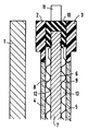
- the figure shows a partial area of a battery with a pressure plate 1 and a structural unit consisting of cell frames 2 and 3, electrodes 4 and 5 and a component 6 according to the invention.
- the battery has two pressure plates and several of these units.
- the cell frame 2 and the electrode 4 are omitted in the terminal unit, ie the unit arranged on the pressure plate 1.
- the component 6 has a metal plate 7, two contact plates 8 and 9 and an elastomer frame 10 with which the metal plate is pressed around the edge.
- the contact plates 8 and 9 are, as shown in the figure, welded to the metal plate 7.
- the metal plate 7 has a metallic tab 11 which is led outwards for the external power connection, preferably radially. Spaces 12 and 13 between the metal plate 7 and the contact plates 8 and 9 serve to receive a fluid for generating pressure.
- the pressure plate 1 is made of plastic or metal coated with plastic.
- the metal plate 7 including the tab 11, i.e. the pole plate is made of copper and is approx. 1 mm thick; it is welded all around between the contact plates 8 and 9.
- the contact plates are only about 0.2 mm thick and therefore flexible, and they are made of nickel, for example.
- the contact plates are also corrugated (height of the corrugations: approx. 1 mm) and thus form gas routes for the gaseous reactants of the battery, for example hydrogen and oxygen, which are fed to electrodes 4 and 5 (pressure: approx. 2 bar each) ; Potassium hydroxide, for example, serves as the electrolyte.
- the pressure medium is nitrogen, for example (pressure: approx. 3 bar).
Landscapes
- Chemical & Material Sciences (AREA)
- Engineering & Computer Science (AREA)
- Electrochemistry (AREA)
- Chemical Kinetics & Catalysis (AREA)
- Sustainable Development (AREA)
- Sustainable Energy (AREA)
- Life Sciences & Earth Sciences (AREA)
- Manufacturing & Machinery (AREA)
- General Chemical & Material Sciences (AREA)
- Materials Engineering (AREA)
- Metallurgy (AREA)
- Organic Chemistry (AREA)
- Fuel Cell (AREA)
- Connection Of Batteries Or Terminals (AREA)
Description
- Die Erfindung betrifft ein Bauteil für den Stromanschluß einer Batterie aus elektrochemischen Zellen, insbesondere Brennstoffelementen, mit Druckkissen in Form von jeweils zwei Kontaktbleche aufweisenden metallischen Kontaktkörpern.
- Eine Batterie der genannten Art mit Druckkissen in Form von metallischen Kontaktkörpern ist aus der DE-PS 27 29 640 bekannt. Die Kontaktkörper dienen dabei einerseits zur Stromabnahme, andererseits weisen sie einen Hohlraum auf, dem ein unter Druck stehendes Medium zuführbar ist, so daß auf das Katalysatormaterial der benachbarten Zellen ein gleichmäßiger Anpreßdruck ausgeübt wird.
- Die elektrochemischen Zellen einer derartigen Batterie sind in bipolarer Weise aufeinandergestapelt, wobei sich am Stapelende jeweils eine Druckplatte befindet. Zwischen den Druckplatten und dem Druckkissen der nächstliegenden Zelle befindet sich jeweils eine Metallplatte, welche eine nach außen überstehende Lasche aufweist, d.h. eine sogenannte Polplatte. Diese Polplatten dienen zur Stromabnahme bzw. zum Stromanschluß.
- Der elektrische Kontakt zwischen den Polplatten und den Druckkissen wird in der Weise hergestellt, daß der Hohlraum der Druckkissen, beispielsweise mittels eines Gases, mit einem Preßdruck beaufschlagt wird. Der elektrische Kontakt kommt aber nur dann zustande, wenn der Zellstapel, d.h. die Batterie, bei Atmosphärendruck betrieben wird oder bei einem Umgebungsdruck, der (deutlich) niedriger ist als der Preßdruck im Inneren der Druckkissen. Liegt der Umgebungsdruck dagegen über dem Preßdruck bzw. steigt er über den Preßdruck an, so wird der Stromfluß entweder unterbrochen oder das Druckkissen wird partiell - wegen undefinierter Kontaktflächen - thermisch überlastet. Dadurch wird aber die Funktionssicherheit der Batterie bzw. von Batterienmoduln gefährdet.
- Es wurde bereits versucht, das vorstehend genannte Problem in der Weise zu lösen, daß die Polplatten in eine Kunststoffplatte eingeklebt wurden. Dann besteht nämlich - nach der Montage des Zellstapels - keine Verbindung mehr zwischen dem Raum zwischen Polplatte und Druckkissen und der umgebenden Atmosphäre, und zwar aufgrund der Abdichtung der in die Kunststoffplatte eingeklebten Polplatte an den Elastomerrahmen.
- Eine derartige Lösung hat aber folgende Nachteile:
- Das Einkleben der Polplatten in Kunststoffplatten ist wegen der unterschiedlichen Wärmeausdehnungskoeffizienten der Materialien und der geometrischen Abmessungen problematisch. Mechanische Spannungen durch das Klebeverfahren selbst und durch thermische Beanspruchungen im Betrieb erzeugen Risse und damit Leckagen von der Umgebung zum Kontaktierungsraum, wodurch die Funktion der Batterie bzw. eines Batteriemoduls beeinträchtigt werden kann.
- Um die Funktion von Batterie bzw. Batteriemodul auch bei kleinen Leckagen sicherzustellen, müssen die Räume zwischen Polplatte und Druckkissen nach außen "entlüftet" werden. Bei schwankendem Druck des Raumes, in den entlüftet wird, sind dadurch relativ aufwendige Vorrichtungen erforderlich, um den Druck am Austritt der Entlüftungsleitung auch bei schwankenden Leckgasmengen möglichst konstant zu halten.
- Die geschilderte Konstruktion ist relativ aufwendig und verursacht deshalb bei mehrfacher Verwendung in einem Zellstapel, beispielsweise bedingt durch eine Parallelschaltung von Zellen oder Zellgruppen, nicht unerhebliche Kosten.
- Aufgabe der Erfindung ist es, ein Bauteil für den Stromanschluß einer Batterie der eingangs genannten Art - mit jeweils zwei Kontaktbleche aufweisenden Kontaktkörpern - anzugeben, das auch einen Betrieb der Batterie bei erhöhtem Umgebungsdruck erlaubt, bei gleichzeitiger Verwendung von Druckkissen zur isostatischen Kontaktdruckerzeugung, und das ferner eine Parallelschaltung von Zellen oder Zellgruppen (innerhalb des Zellstapels) ermöglicht.
- Dies wird erfindungsgemäß dadurch erreicht, daß zwischen die beiden Kontaktbleche jedes Kontaktkörpers eine Metallplatte umlaufend eingeschweißt ist, daß die Metallplatte eine nach außen überstehende metallische Lasche aufweist, und daß die Metallplatte am Rand mit einem Elastomeren versehen ist.
- Beim Bauteil nach der vorliegenden Erfindung ist die Polplatte in das Druckkissen integriert. Dies bringt sowohl funktionstechnische als auch fertigungstechnische Vorteile mit sich, d.h. ein derartiges Bauteil ist in fertigungstechnischer Hinsicht relativ einfach zu realisieren. Darüber hinaus werden bei der Verwendung des erfindungsgemäßen Bauteils sämtliche der vorstehend genannten Probleme beseitigt.
- Vorteilhafte Ausgestaltungen des Bauteils nach der Erfindung bestehen darin, daß die Metallplatte und die metallische Lasche aus Kupfer bestehen, und daß die Kontaktbleche wellenförmig geprägt sind.
- Anhand einer Figur, in der eine vorteilhafte Ausführungsform des erfindungsgemäßen Bauteils schematisch im Schnitt dargestellt ist, soll die Erfindung noch näher erläutert werden.
- Die Figur zeigt einen Teilbereich einer Batterie mit einer Druckplatte 1 und einer aus Zellrahmen 2 und 3, Elektroden 4 und 5 sowie einem Bauteil 6 nach der Erfindung bestehenden Baueinheit. Die Batterie weist zwei Druckplatten und mehrere dieser Baueinheiten auf. Bei der endständigen, d.h. der an der Druckplatte 1 angeordneten Baueinheit entfallen dabei der Zellrahmen 2 und die Elektrode 4.
- Das Bauteil 6 weist eine Metallplatte 7, zwei Kontaktbleche 8 und 9 sowie einen Elastomerrahmen 10 auf, mit dem die Metallplatte am Rand umpreßt ist. Die Kontaktbleche 8 und 9 sind, wie in der Figur dargestellt ist, mit der Metallplatte 7 verschweißt. Die Metallplatte 7 besitzt eine metallische Lasche 11, die für den äußeren Stromanschluß nach außen geführt ist, vorzugsweise radial. Räume 12 und 13 zwischen der Metallplatte 7 und den Kontaktblechen 8 bzw. 9 dienen zur Aufnahme eines Fluids zur Druckerzeugung.
- Die Druckplatte 1 besteht aus Kunststoff oder mit Kunststoff überzogenem Metall. Die Metallplatte 7 samt Lasche 11, d.h. die Polplatte, besteht aus Kupfer und ist ca. 1 mm dick; sie ist umlaufend zwischen die Kontaktbleche 8 und 9 eingeschweißt. Die Kontaktbleche sind lediglich ca. 0,2 mm dick und deshalb flexibel, und sie bestehen beispielsweise aus Nickel. Die Kontaktbleche sind ferner wellenförmig geprägt (Höhe der Wellungen: ca. 1 mm) und bilden somit Gasleitwege für die gasförmigen Reaktanten der Batterie, beispielsweise Wasserstoff und Sauerstoff, die den Elektroden 4 bzw. 5 zugeführt werden (Druck: jeweils ca. 2 bar); als Elektrolyt dient beispielsweise Kalilauge. Das Druckmedium ist beispielsweise Stickstoff (Druck: ca. 3 bar).
Claims (3)
- Bauteil für den Stromanschluß einer Batterie aus elektrochemischen Zellen, insbesondere Brennstoffelementen, mit Druckkissen in Form von jeweils zwei Kontaktbleche aufweisenden metallischen Kontaktkörpern, dadurch gekennzeichnet, daß zwischen die beiden Kontaktbleche (8, 9) jedes Kontaktkörpers eine Metallplatte (7) umlaufend eingeschweißt ist, daß die Metallplatte (7) eine nach außen überstehende metallische Lasche (11) aufweist, und daß die Metallplatte (7) am Rand mit einem Elastomerrahmen (10) versehen ist.
- Bauteil nach Anspruch 1, dadurch gekennzeichnet, daß die Metallplatte (7) und die metallische Lasche (11) aus Kupfer bestehen.
- Bauteil nach Anspruch 1 oder 2, dadurch gekennzeichnet, daß die Kontaktbleche (8, 9) wellenförmig geprägt sind.
Applications Claiming Priority (2)
| Application Number | Priority Date | Filing Date | Title |
|---|---|---|---|
| DE3732235 | 1987-09-24 | ||
| DE3732235 | 1987-09-24 |
Publications (2)
| Publication Number | Publication Date |
|---|---|
| EP0308761A1 EP0308761A1 (de) | 1989-03-29 |
| EP0308761B1 true EP0308761B1 (de) | 1992-03-11 |
Family
ID=6336812
Family Applications (1)
| Application Number | Title | Priority Date | Filing Date |
|---|---|---|---|
| EP88114890A Expired - Lifetime EP0308761B1 (de) | 1987-09-24 | 1988-09-12 | Bauteil für den Stromanschluss einer Batterie aus elektrochemischen Zellen |
Country Status (5)
| Country | Link |
|---|---|
| US (1) | US4844992A (de) |
| EP (1) | EP0308761B1 (de) |
| JP (1) | JPH01102857A (de) |
| CA (1) | CA1309131C (de) |
| DE (1) | DE3869030D1 (de) |
Families Citing this family (9)
| Publication number | Priority date | Publication date | Assignee | Title |
|---|---|---|---|---|
| JPH04298963A (ja) * | 1991-03-27 | 1992-10-22 | Ngk Insulators Ltd | 固体電解質型燃料電池及びその製造方法 |
| JP3135991B2 (ja) * | 1992-06-18 | 2001-02-19 | 本田技研工業株式会社 | 燃料電池および燃料電池スタック締め付け方法 |
| DE4340153C1 (de) * | 1993-11-25 | 1995-03-09 | Solentec Ges Fuer Solare Und E | Vorrichtung zum Kontaktieren von Elektroden von Hochtemperatur-Brennstoffzellen |
| DE19734634C1 (de) * | 1997-08-11 | 1999-01-07 | Forschungszentrum Juelich Gmbh | Brennstoffzelle zur direkten Verstromung von Methanol |
| EP1327273A2 (de) * | 2000-09-27 | 2003-07-16 | Proton Energy Systems | Mittel zur aufrechterhaltung von druck auf der aktiven fläche in einer elektrochemischen zelle |
| WO2002027851A2 (en) | 2000-09-27 | 2002-04-04 | Proton Energy Systems, Inc. | Method and apparatus for maintaining compression of the active area in an electrochemical cell |
| US6869720B2 (en) | 2000-09-27 | 2005-03-22 | Proton Energy Systems, Inc. | Method and apparatus for maintaining compression of the active area in an electrochemical cell |
| DE10323883A1 (de) | 2003-05-26 | 2004-12-30 | Siemens Ag | Elektrochemische Batterie |
| DE102010051748A1 (de) * | 2010-11-19 | 2012-05-24 | Gräbener Maschinentechnik GmbH & Co. KG | Modulares Brennstoffzellensystem |
Family Cites Families (4)
| Publication number | Priority date | Publication date | Assignee | Title |
|---|---|---|---|---|
| FR1433469A (fr) * | 1965-02-16 | 1966-04-01 | Thomson Houston Comp Francaise | Perfectionnements aux piles à combustibles |
| DE1938044C3 (de) * | 1969-07-26 | 1979-03-01 | Siemens Ag, 1000 Berlin Und 8000 Muenchen | Bauteil für Brennstoffelemente und mittels dieses Bauteils hergestellte |
| FR2224206A1 (en) * | 1973-04-06 | 1974-10-31 | Alsthom Cgee | Internally pressurised bellows arrangement - acting as electrode separator in electrochemical systems |
| DE2729640C3 (de) * | 1977-06-30 | 1980-07-24 | Siemens Ag, 1000 Berlin Und 8000 Muenchen | Batterie aus einer Mehrzahl elektrochemischer Zellen |
-
1988
- 1988-09-12 EP EP88114890A patent/EP0308761B1/de not_active Expired - Lifetime
- 1988-09-12 DE DE8888114890T patent/DE3869030D1/de not_active Expired - Lifetime
- 1988-09-21 JP JP63237442A patent/JPH01102857A/ja active Pending
- 1988-09-22 CA CA000578106A patent/CA1309131C/en not_active Expired - Lifetime
- 1988-09-23 US US07/248,432 patent/US4844992A/en not_active Expired - Fee Related
Also Published As
| Publication number | Publication date |
|---|---|
| EP0308761A1 (de) | 1989-03-29 |
| DE3869030D1 (de) | 1992-04-16 |
| CA1309131C (en) | 1992-10-20 |
| US4844992A (en) | 1989-07-04 |
| JPH01102857A (ja) | 1989-04-20 |
Similar Documents
| Publication | Publication Date | Title |
|---|---|---|
| DE102018201497C5 (de) | Brennstoffzelle und metallischer Separator für eine Brennstoffzelle | |
| DE10047248A1 (de) | Elektrochemischer Zellenstapel | |
| DE112007002945B4 (de) | Brennstoffzelle mit elastischem Element | |
| DE202014004456U1 (de) | Metallische Bipolarplatte mit rückfedernder Dichtungsanordnung und elektrochemisches System | |
| DE102017213964B4 (de) | Separator für eine Brennstoffzelle und Elementarzelle einer Brennstoffzelle | |
| DE20308332U1 (de) | Elektrochemisches Verdichtersystem | |
| WO2003044886A2 (de) | Brennstoffzellensystem | |
| EP0591800A1 (de) | Bauelement zum Einbau in eine verfahrenstechnische Einrichtung | |
| EP0635896A1 (de) | Zentralsymmetrische Brennstoffzellenbatterie | |
| EP1314217B1 (de) | Hochtemperaturbrennstoffzelle | |
| DE10063720A1 (de) | Niedertemperatur-Brennstoffzelle | |
| DE102018211877A1 (de) | Zellrahmen für Brennstoffzelle und Brennstoffzellenstapel, der denselben verwendet | |
| DE4443688C1 (de) | Bipolarplatte für Brennstoffzellen | |
| DE102017101318A1 (de) | Geprägte metalldichtungskonstruktion mit verbesserter kontaktdruckgleichförmigkeit unter fehlausrichtungsbedingungen | |
| EP4166691A1 (de) | Rahmen für pem elektrolysezellen und pem elektrolysezellen stapel zur erzeugung von hochdruck-wasserstoff mittels differenzdruckelektrolyse | |
| DE112004000783T5 (de) | Brennstoffzelle | |
| EP0308761A1 (de) | Bauteil für den Stromanschluss einer Batterie aus elektrochemischen Zellen | |
| DE112007001807T5 (de) | Brennstoffzelle | |
| WO2024183850A1 (de) | Elektrochemischer zellenstapel | |
| EP1589602B1 (de) | Kontaktfederblech und elektrochemische Batterie mit einem derartigen Kontaktfederblech | |
| DE102005014077B4 (de) | Interkonnektor für Hochtemperaturbrennstoffzellen und Verfahren zu dessen Herstellung und Verfahren zum Betreiben einer Brennstoffzelle | |
| WO2022128856A2 (de) | Anordnung elektrochemischer zellen | |
| DE102009047178A1 (de) | Elastischer Befestigungsrahmen | |
| WO2022028998A1 (de) | Verfahren zur reduzierung des kontaktwiderstands zwischen einer separatorplatte und einer gasdiffusionslage einer brennstoffzelle, separatorplatte | |
| DE202023105129U1 (de) | Bipolarplatte für ein elektrochemisches System mit einem Abstützelement |
Legal Events
| Date | Code | Title | Description |
|---|---|---|---|
| PUAI | Public reference made under article 153(3) epc to a published international application that has entered the european phase |
Free format text: ORIGINAL CODE: 0009012 |
|
| AK | Designated contracting states |
Kind code of ref document: A1 Designated state(s): BE DE FR GB IT NL |
|
| 17P | Request for examination filed |
Effective date: 19890928 |
|
| 17Q | First examination report despatched |
Effective date: 19910419 |
|
| GRAA | (expected) grant |
Free format text: ORIGINAL CODE: 0009210 |
|
| AK | Designated contracting states |
Kind code of ref document: B1 Designated state(s): BE DE FR GB IT NL |
|
| REF | Corresponds to: |
Ref document number: 3869030 Country of ref document: DE Date of ref document: 19920416 |
|
| ET | Fr: translation filed | ||
| ITF | It: translation for a ep patent filed | ||
| GBT | Gb: translation of ep patent filed (gb section 77(6)(a)/1977) | ||
| PLBE | No opposition filed within time limit |
Free format text: ORIGINAL CODE: 0009261 |
|
| STAA | Information on the status of an ep patent application or granted ep patent |
Free format text: STATUS: NO OPPOSITION FILED WITHIN TIME LIMIT |
|
| 26N | No opposition filed | ||
| PGFP | Annual fee paid to national office [announced via postgrant information from national office to epo] |
Ref country code: GB Payment date: 19940815 Year of fee payment: 7 |
|
| PGFP | Annual fee paid to national office [announced via postgrant information from national office to epo] |
Ref country code: BE Payment date: 19940912 Year of fee payment: 7 |
|
| PGFP | Annual fee paid to national office [announced via postgrant information from national office to epo] |
Ref country code: FR Payment date: 19940920 Year of fee payment: 7 |
|
| PGFP | Annual fee paid to national office [announced via postgrant information from national office to epo] |
Ref country code: NL Payment date: 19940930 Year of fee payment: 7 |
|
| PGFP | Annual fee paid to national office [announced via postgrant information from national office to epo] |
Ref country code: DE Payment date: 19941118 Year of fee payment: 7 |
|
| PG25 | Lapsed in a contracting state [announced via postgrant information from national office to epo] |
Ref country code: GB Effective date: 19950912 |
|
| PG25 | Lapsed in a contracting state [announced via postgrant information from national office to epo] |
Ref country code: BE Effective date: 19950930 |
|
| BERE | Be: lapsed |
Owner name: SIEMENS A.G. Effective date: 19950930 |
|
| PG25 | Lapsed in a contracting state [announced via postgrant information from national office to epo] |
Ref country code: NL Effective date: 19960401 |
|
| GBPC | Gb: european patent ceased through non-payment of renewal fee |
Effective date: 19950912 |
|
| PG25 | Lapsed in a contracting state [announced via postgrant information from national office to epo] |
Ref country code: FR Effective date: 19960531 |
|
| PG25 | Lapsed in a contracting state [announced via postgrant information from national office to epo] |
Ref country code: DE Effective date: 19960601 |
|
| NLV4 | Nl: lapsed or anulled due to non-payment of the annual fee |
Effective date: 19960401 |
|
| REG | Reference to a national code |
Ref country code: FR Ref legal event code: ST |
|
| PG25 | Lapsed in a contracting state [announced via postgrant information from national office to epo] |
Ref country code: IT Free format text: LAPSE BECAUSE OF NON-PAYMENT OF DUE FEES;WARNING: LAPSES OF ITALIAN PATENTS WITH EFFECTIVE DATE BEFORE 2007 MAY HAVE OCCURRED AT ANY TIME BEFORE 2007. THE CORRECT EFFECTIVE DATE MAY BE DIFFERENT FROM THE ONE RECORDED. Effective date: 20050912 |