EP0308879A2 - Rouage à deux moteurs, en particulier pour montre réceptrice - Google Patents
Rouage à deux moteurs, en particulier pour montre réceptrice Download PDFInfo
- Publication number
- EP0308879A2 EP0308879A2 EP88115449A EP88115449A EP0308879A2 EP 0308879 A2 EP0308879 A2 EP 0308879A2 EP 88115449 A EP88115449 A EP 88115449A EP 88115449 A EP88115449 A EP 88115449A EP 0308879 A2 EP0308879 A2 EP 0308879A2
- Authority
- EP
- European Patent Office
- Prior art keywords
- wheel
- gear train
- light barrier
- minute
- hour
- Prior art date
- Legal status (The legal status is an assumption and is not a legal conclusion. Google has not performed a legal analysis and makes no representation as to the accuracy of the status listed.)
- Granted
Links
Images
Classifications
-
- G—PHYSICS
- G04—HOROLOGY
- G04C—ELECTROMECHANICAL CLOCKS OR WATCHES
- G04C3/00—Electromechanical clocks or watches independent of other time-pieces and in which the movement is maintained by electric means
- G04C3/14—Electromechanical clocks or watches independent of other time-pieces and in which the movement is maintained by electric means incorporating a stepping motor
- G04C3/143—Means to reduce power consumption by reducing pulse width or amplitude and related problems, e.g. detection of unwanted or missing step
-
- G—PHYSICS
- G04—HOROLOGY
- G04C—ELECTROMECHANICAL CLOCKS OR WATCHES
- G04C3/00—Electromechanical clocks or watches independent of other time-pieces and in which the movement is maintained by electric means
- G04C3/001—Electromechanical switches for setting or display
Definitions
- the invention relates to a gear train according to the preamble of claim 1.
- Such a gear train is known from US Pat. No. 4,645,357 with separate motors for the one hand the second hand and on the other hand the minute hand and the hour hand coupled with it, each with a light barrier assigned to one of the two motors for the detection of a specific gear train position.
- the invention has for its object to develop a generic type of gear such that more favorable conditions for screwing the pointers into a defined position can be realized in terms of energy and time requirements and at the same time simpler possibilities for the implementation of the light barriers and for gear function tests are opened.
- each of the motors only has to deliver a relatively low torque.
- the hour bike is operated from its own motor, which also means a high movement resolution (number of steps for the further movement by an hour division) without consideration allows the gear conditions of the rest of the gear train.
- the other motor is to be designed anyway for the torque required to move the longest of all hands, the second hand, and the movement of the minute hand derived therefrom in the gear ratio 60: 1 does not represent any noticeable additional load for the other motor in these reduction conditions from the own drive of the second hand minute hand wheel part a fine step division and thus a very precise minute display on the minute track of the watch, because the movement from one minute mark to the next minute mark is resolved to 60 increments.
- the separate drive of the hour wheel also opens up a particularly simple implementation option for the light barrier for angular position detection, because the query of the position of the hour indicator is not necessary for one motor step, so that the position of a single aperture hole in the hour wheel is simply queried by means of a compact reflex light barrier can be. Since no other wheels of the factory are included in this light barrier query, the hour wheel can be set in any angular position, regardless of the current position of any other wheels of the factory, i.e. without the need for a wheel pre-adjustment during factory assembly.
- Transmitter and receiver of the light barriers can be mounted on a common circuit board, which also carries the other circuits, to reduce the manufacturing and assembly work, with the beam path reflectors being formed by metal mirrors on the walls of the movement housing beyond the respective sub-gear train. Because, according to the solution according to the invention, there is no longer any gear coupling between the hour wheel on the one hand and the minute or second wheel on the other, an urgent correction of the hour display (for example for the change from summer time to winter time or to the change of time zone) can be done without impairing the momentary setting of the minute and hour hands. be carried out in an optimally short time, since this requires only the fastest possible activation of the hour wheel motor in order to carry out the corresponding number of steps. Because, accordingly, rapid advancement by 11 hours can easily be realized, the effort of a bidirectional drive for the correction by "one hour back" is eliminated without requiring unreasonably long periods of time for this correction.
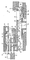
- the gear train 11 of a radio-controlled clock 10 is constructed in a movement housing 12 essentially with a floating bearing on a carrier plate 13 with axial play limitation of the bearing position by appropriate distance measurement to the housing rear wall 14, as explained in more detail in detail in US Pat. No. 4,465,378.
- a motor 15 preferably embodied as a miniature stepper motor operated in a time-keeping manner, uses its pinion 16 to drive an intermediate wheel 17 for the movement of a second wheel 18, which in turn is geared to the minute wheel 20 via a small bottom wheel 19 to reduce movement.
- the turning of the hour wheel 21 into a certain angular position with respect to the work housing 12 is detected by means of a reflex light barrier 27, which is designed as a compact transmitter-receiver module , if the beam path 28 - without interruption by the hour wheel 21 - is given continuously via a reflector 29.
- This passage of the beam path 28 can only be achieved in an angular position of the hour wheel 21, namely when an aperture hole 30 formed in the hour wheel 21 has just pivoted in via the reflector 29 with a sufficient projection surface.
- the reflex light barrier 27 is equipped with a capture circuit 31 which ensures the first response of the light barrier 27 when screwing in the aperture hole 30.
- the capture circuit 31 when the light barrier transmitter is only activated in pulse mode in order to save energy, it is not the same as the reception pulse for the angular position processing which occurs when screwing in at the leading edge of the aperture hole 30, but rather the through Only release the circuit to the synchronization device when several receive pulses have occurred in succession in the rhythm of the transmitter control, that is, when the aperture hole 30 has been screwed into the beam path 28 over a large area (and also does not lead to an interruption of the beam path 28 due to the rotational movement play).
- the capture circuit 31 can also be designed simply as a memory circuit which, when it is excited for the first time by the light barrier receive pulse, tilts into a signaling position and continuously delivers the detection signal to the evaluation circuit for a certain time, regardless of whether the transmission clearance causes it shortly thereafter Beam path 28 is interrupted again.
- a deflection light barrier is shown in the design of the gear train independently of the hour wheel light barrier 27 33 is provided, the beam path 34 of which leads through structurally predetermined holes 35 in the carrier plate 13 and in a circuit board 36 held in front of it - while freeing up a space for the minute wheel 20 - and via deflection reflectors 37 on the rear housing wall 14.
- This beam path 34 is only released if it also leads through aperture 38 of all gear wheels protruding here.
- the defined angular position on the part of the second and minute wheel 18, 20 is reached when one of two aperture holes 38 provided in the minute wheel 20 lies simultaneously with the aperture hole 38 provided in the intermediate wheel 17 and with the aperture hole 38 provided in the second wheel 18 in the path of the steel gear 34.
- the reflectors 29, 37 can simply be designed as small, if necessary surface-treated metal parts fastened to the corresponding wall 14, 40 of the work housing 12; the deflecting reflectors 37 can be designed as angled ends of a metal strip 41 (as indicated in the drawing), or as individual metal plates inserted into the rear wall holding slots 42.
- the control circuits 31, 32 and the light barriers 27, 33 (irrespective of whether in a one-piece transmitter-receiver design according to the reflex light barrier 27 or with separate mounting of the transmitter and receiver as in the case the deflecting light barrier 33) so that all wiring can be implemented as printed line lamination on the printed circuit board 36.
- This also expediently carries a test circuit 43 (possibly integrated in one of the other circuits), which delivers a pulse packet with a predetermined number of motor control pulses during commissioning. This number is predetermined so that the corresponding part of the gear train 11 would have to rotate straight out of a detection position into the next detection position (ie until the next occurrence of the uninterrupted beam path 28 or 34). As a result, it can be determined in a particularly simple manner and independently of one another for the hour hand and for the minute hand whether there are any gear or other errors in the gear train 11.
- a time zone correction circuit 44 can be provided which, when the time zone is changed, rotates the hour stepper motor 24 (and only this) for one or more hours (30 degree angle) for further rotation of the hour wheel 21, or by rotates one hour or eleven hours to switch between summer time and winter time. Because the entire gear train 11 does not have to be moved for such hour jump time display corrections, but only the hour wheel 21 is driven, this can be achieved particularly quickly with low energy requirements.
Landscapes
- Physics & Mathematics (AREA)
- General Physics & Mathematics (AREA)
- Electromechanical Clocks (AREA)
Applications Claiming Priority (2)
| Application Number | Priority Date | Filing Date | Title |
|---|---|---|---|
| DE8712809U DE8712809U1 (de) | 1987-09-23 | 1987-09-23 | Zweimotoren-Räderwerk, insbesondere für eine Funkuhr |
| DE8712809U | 1987-09-23 |
Publications (4)
| Publication Number | Publication Date |
|---|---|
| EP0308879A2 true EP0308879A2 (fr) | 1989-03-29 |
| EP0308879A3 EP0308879A3 (fr) | 1991-03-27 |
| EP0308879B1 EP0308879B1 (fr) | 1993-04-28 |
| EP0308879B2 EP0308879B2 (fr) | 1996-05-08 |
Family
ID=6812342
Family Applications (1)
| Application Number | Title | Priority Date | Filing Date |
|---|---|---|---|
| EP88115449A Expired - Lifetime EP0308879B2 (fr) | 1987-09-23 | 1988-09-21 | Rouage à deux moteurs, en particulier pour montre réceptrice |
Country Status (2)
| Country | Link |
|---|---|
| EP (1) | EP0308879B2 (fr) |
| DE (2) | DE8712809U1 (fr) |
Cited By (5)
| Publication number | Priority date | Publication date | Assignee | Title |
|---|---|---|---|---|
| EP0788623A4 (fr) * | 1992-09-04 | 1998-01-28 | Madhav N Damle | Horloge de haute precision a remise a l'heure telecommandee |
| GB2319638B (en) * | 1996-11-06 | 2000-12-13 | Seiko Clock Inc | Timepiece movement |
| GB2352061A (en) * | 1996-11-06 | 2001-01-17 | Seiko Clock Inc | Timepiece movement |
| WO2003091810A3 (fr) * | 2002-04-26 | 2004-06-17 | Kienzle Time Hong Kong Ltd | Horloge radiocommandee |
| EP1413935A3 (fr) * | 2002-10-21 | 2005-06-22 | Seiko Instruments Inc. | Dispositif pour détecter une position rotative, dispositif pour détecter la position d'une aiguille, et montre utilisant ce dispositif pour détecter la position d'une aiguille |
Families Citing this family (1)
| Publication number | Priority date | Publication date | Assignee | Title |
|---|---|---|---|---|
| DD277540A1 (de) * | 1988-11-30 | 1990-04-04 | Ruhla Uhren Veb K | Raederwerk |
Family Cites Families (3)
| Publication number | Priority date | Publication date | Assignee | Title |
|---|---|---|---|---|
| CH646301GA3 (fr) * | 1981-12-23 | 1984-11-30 | ||
| DE3510861C2 (de) * | 1984-11-09 | 1986-09-25 | Gebrüder Junghans GmbH, 7230 Schramberg | Anzeigestellungs-Detektionseinrichtung für eine Uhr, insbesondere eine Funkuhr |
| DE3513961A1 (de) * | 1985-04-18 | 1986-10-23 | Forschungsgesellschaft für Feingeräte-, Mikro- und Uhrentechnik e.V., 7000 Stuttgart | Getriebestandserfassungseinrichtung bei einer elektronischen uhr insbesondere funkgesteuerte uhr |
-
1987
- 1987-09-23 DE DE8712809U patent/DE8712809U1/de not_active Expired
-
1988
- 1988-09-21 DE DE8888115449T patent/DE3880603D1/de not_active Expired - Fee Related
- 1988-09-21 EP EP88115449A patent/EP0308879B2/fr not_active Expired - Lifetime
Cited By (6)
| Publication number | Priority date | Publication date | Assignee | Title |
|---|---|---|---|---|
| EP0788623A4 (fr) * | 1992-09-04 | 1998-01-28 | Madhav N Damle | Horloge de haute precision a remise a l'heure telecommandee |
| GB2319638B (en) * | 1996-11-06 | 2000-12-13 | Seiko Clock Inc | Timepiece movement |
| GB2352061A (en) * | 1996-11-06 | 2001-01-17 | Seiko Clock Inc | Timepiece movement |
| GB2352061B (en) * | 1996-11-06 | 2001-03-28 | Seiko Clock Inc | Timepiece movement |
| WO2003091810A3 (fr) * | 2002-04-26 | 2004-06-17 | Kienzle Time Hong Kong Ltd | Horloge radiocommandee |
| EP1413935A3 (fr) * | 2002-10-21 | 2005-06-22 | Seiko Instruments Inc. | Dispositif pour détecter une position rotative, dispositif pour détecter la position d'une aiguille, et montre utilisant ce dispositif pour détecter la position d'une aiguille |
Also Published As
| Publication number | Publication date |
|---|---|
| DE8712809U1 (de) | 1987-11-05 |
| EP0308879B1 (fr) | 1993-04-28 |
| EP0308879B2 (fr) | 1996-05-08 |
| EP0308879A3 (fr) | 1991-03-27 |
| DE3880603D1 (de) | 1993-06-03 |
Similar Documents
| Publication | Publication Date | Title |
|---|---|---|
| DE4128752C2 (de) | Stellungsdetektions- und -Korrektureinrichtung | |
| EP0180880B1 (fr) | Dispositif de détection de la position de l'affichage d'une montre, en particulier une montre à radiocommande | |
| DE19749140B4 (de) | Uhrwerk | |
| EP0308879A2 (fr) | Rouage à deux moteurs, en particulier pour montre réceptrice | |
| DE4236903C2 (de) | Funkgesteuertes Uhrwerk | |
| DE3902353A1 (de) | Uhrwerk fuer eine elektrische uhr | |
| DE3510636C3 (de) | Autonome Funkuhr mit Zeitpunkt-Signalgeber | |
| DE8432847U1 (de) | Zeigerstellungs-Detektionseinrichtung für eine Uhr, insbesondere eine Funkuhr | |
| DE3817519A1 (de) | Steuerungs- oder korrekturvorrichtung der tages- oder datumsanzeige fuer eine uhr, besonders eine armbanduhr | |
| DE3421189A1 (de) | Elektrische uhr | |
| DE1905202B2 (de) | Synchronisationseinrichtung für zeithaltende Geräte | |
| DE2617077C3 (de) | Quarzgesteuerte Analog-Armbanduhr mit direktem Antrieb des Minutenrades | |
| DE9117162U1 (de) | Stellungsdetektions- und Korrektureinrichtung | |
| DE2753733A1 (de) | Zeitgesteuertes schlagwerk | |
| DE9308888U1 (de) | Vorrichtung zum Anzeigen des Beginns der Parkzeit | |
| DE1773923A1 (de) | Nebenuhr mit einem elektromagnetischen Fortschaltantrieb | |
| EP0513429A2 (fr) | Indicateur de début de temps de stationnement | |
| DE10159010B4 (de) | Elektromechanische Schaltuhr | |
| DE1548036C (de) | Uhrwerk mit einem frequenzab hangig steuerbaren Haupt und einem von der als Gangreserve dienenden Gleichspannungsquelle gespeisten Hilfsantnebssystem | |
| DE3426459C2 (de) | Stelleinrichtung für eine elektromotorisch angetriebene Uhr | |
| DE3011965C2 (de) | Elektronische Uhr | |
| DE4033584A1 (de) | Automatische verstelleinrichtung fuer durch eine haupt-zeitschaltuhr gesteuerte nebenuhren | |
| DE9414266U1 (de) | Autonome kleine Funkuhr, insbesondere Funk-Armbanduhr | |
| EP0664496A2 (fr) | Montre à affichage de temps commutable, en particulier réveil commandé par radio à affichage digital de temps d'alarme | |
| DE4319224A1 (de) | Vorrichtung zum Anzeigen des Beginns der Parkzeit |
Legal Events
| Date | Code | Title | Description |
|---|---|---|---|
| PUAI | Public reference made under article 153(3) epc to a published international application that has entered the european phase |
Free format text: ORIGINAL CODE: 0009012 |
|
| AK | Designated contracting states |
Kind code of ref document: A2 Designated state(s): CH DE FR GB IT LI |
|
| PUAL | Search report despatched |
Free format text: ORIGINAL CODE: 0009013 |
|
| AK | Designated contracting states |
Kind code of ref document: A3 Designated state(s): CH DE FR GB IT LI |
|
| 17P | Request for examination filed |
Effective date: 19910330 |
|
| 17Q | First examination report despatched |
Effective date: 19911220 |
|
| GRAA | (expected) grant |
Free format text: ORIGINAL CODE: 0009210 |
|
| AK | Designated contracting states |
Kind code of ref document: B1 Designated state(s): CH DE FR GB IT LI |
|
| REF | Corresponds to: |
Ref document number: 3880603 Country of ref document: DE Date of ref document: 19930603 |
|
| ITF | It: translation for a ep patent filed | ||
| ET | Fr: translation filed | ||
| GBT | Gb: translation of ep patent filed (gb section 77(6)(a)/1977) |
Effective date: 19930714 |
|
| PLBI | Opposition filed |
Free format text: ORIGINAL CODE: 0009260 |
|
| 26 | Opposition filed |
Opponent name: ETA SA FABRIQUES D'EBAUCHES Effective date: 19940126 |
|
| GRAH | Despatch of communication of intention to grant a patent |
Free format text: ORIGINAL CODE: EPIDOS IGRA |
|
| PUAH | Patent maintained in amended form |
Free format text: ORIGINAL CODE: 0009272 |
|
| STAA | Information on the status of an ep patent application or granted ep patent |
Free format text: STATUS: PATENT MAINTAINED AS AMENDED |
|
| 27A | Patent maintained in amended form |
Effective date: 19960508 |
|
| AK | Designated contracting states |
Kind code of ref document: B2 Designated state(s): CH DE FR GB IT LI |
|
| REG | Reference to a national code |
Ref country code: CH Ref legal event code: AEN Free format text: AUFRECHTERHALTUNG DES PATENTES IN GEAENDERTER FORM |
|
| GBTA | Gb: translation of amended ep patent filed (gb section 77(6)(b)/1977) |
Effective date: 19960619 |
|
| ITF | It: translation for a ep patent filed | ||
| ET3 | Fr: translation filed ** decision concerning opposition | ||
| PGFP | Annual fee paid to national office [announced via postgrant information from national office to epo] |
Ref country code: FR Payment date: 19980730 Year of fee payment: 11 |
|
| PGFP | Annual fee paid to national office [announced via postgrant information from national office to epo] |
Ref country code: CH Payment date: 19980818 Year of fee payment: 11 |
|
| PGFP | Annual fee paid to national office [announced via postgrant information from national office to epo] |
Ref country code: GB Payment date: 19990913 Year of fee payment: 12 |
|
| PG25 | Lapsed in a contracting state [announced via postgrant information from national office to epo] |
Ref country code: LI Free format text: LAPSE BECAUSE OF NON-PAYMENT OF DUE FEES Effective date: 19990930 Ref country code: CH Free format text: LAPSE BECAUSE OF NON-PAYMENT OF DUE FEES Effective date: 19990930 |
|
| REG | Reference to a national code |
Ref country code: CH Ref legal event code: PL |
|
| PG25 | Lapsed in a contracting state [announced via postgrant information from national office to epo] |
Ref country code: FR Free format text: LAPSE BECAUSE OF NON-PAYMENT OF DUE FEES Effective date: 20000531 |
|
| REG | Reference to a national code |
Ref country code: FR Ref legal event code: ST |
|
| PG25 | Lapsed in a contracting state [announced via postgrant information from national office to epo] |
Ref country code: GB Free format text: LAPSE BECAUSE OF NON-PAYMENT OF DUE FEES Effective date: 20000921 |
|
| GBPC | Gb: european patent ceased through non-payment of renewal fee |
Effective date: 20000921 |
|
| PGFP | Annual fee paid to national office [announced via postgrant information from national office to epo] |
Ref country code: DE Payment date: 20041122 Year of fee payment: 17 |
|
| PG25 | Lapsed in a contracting state [announced via postgrant information from national office to epo] |
Ref country code: IT Free format text: LAPSE BECAUSE OF NON-PAYMENT OF DUE FEES;WARNING: LAPSES OF ITALIAN PATENTS WITH EFFECTIVE DATE BEFORE 2007 MAY HAVE OCCURRED AT ANY TIME BEFORE 2007. THE CORRECT EFFECTIVE DATE MAY BE DIFFERENT FROM THE ONE RECORDED. Effective date: 20050921 |
|
| PG25 | Lapsed in a contracting state [announced via postgrant information from national office to epo] |
Ref country code: DE Free format text: LAPSE BECAUSE OF NON-PAYMENT OF DUE FEES Effective date: 20060401 |