EP0308949A2 - Séparateur de liquides légers - Google Patents
Séparateur de liquides légers Download PDFInfo
- Publication number
- EP0308949A2 EP0308949A2 EP19880115636 EP88115636A EP0308949A2 EP 0308949 A2 EP0308949 A2 EP 0308949A2 EP 19880115636 EP19880115636 EP 19880115636 EP 88115636 A EP88115636 A EP 88115636A EP 0308949 A2 EP0308949 A2 EP 0308949A2
- Authority
- EP
- European Patent Office
- Prior art keywords
- light liquid
- liquid
- heavy
- separator
- light
- Prior art date
- Legal status (The legal status is an assumption and is not a legal conclusion. Google has not performed a legal analysis and makes no representation as to the accuracy of the status listed.)
- Granted
Links
Images






Classifications
-
- E—FIXED CONSTRUCTIONS
- E03—WATER SUPPLY; SEWERAGE
- E03F—SEWERS; CESSPOOLS
- E03F5/00—Sewerage structures
- E03F5/14—Devices for separating liquid or solid substances from sewage, e.g. sand or sludge traps, rakes or grates
- E03F5/16—Devices for separating oil, water or grease from sewage in drains leading to the main sewer
-
- B—PERFORMING OPERATIONS; TRANSPORTING
- B01—PHYSICAL OR CHEMICAL PROCESSES OR APPARATUS IN GENERAL
- B01D—SEPARATION
- B01D17/00—Separation of liquids, not provided for elsewhere, e.g. by thermal diffusion
- B01D17/02—Separation of non-miscible liquids
- B01D17/0208—Separation of non-miscible liquids by sedimentation
-
- B—PERFORMING OPERATIONS; TRANSPORTING
- B01—PHYSICAL OR CHEMICAL PROCESSES OR APPARATUS IN GENERAL
- B01D—SEPARATION
- B01D17/00—Separation of liquids, not provided for elsewhere, e.g. by thermal diffusion
- B01D17/02—Separation of non-miscible liquids
- B01D17/0208—Separation of non-miscible liquids by sedimentation
- B01D17/0214—Separation of non-miscible liquids by sedimentation with removal of one of the phases
Definitions
- the present invention relates to a light liquid separator with an inlet for a light liquid-heavy liquid mixture, a separating chamber for separating light liquid and heavy liquid, an outlet for the light liquid and an outlet for the heavy liquid, which has an overflow edge and a small drain opening in the area of the drain bottom he follows.
- Such a light liquid separator is known for example from DE-OS 33 03 632, which goes back to the same applicant.
- this known separator at least one light liquid drain is provided in the form of a bell with an upward pipe. If the known separator has a coarse separation chamber and a fine separation chamber, each chamber has its own light liquid drain of this type. In the known separator, therefore, the light liquid drain takes place from the whole Area of the separating chamber and, if the chamber is divided into a coarse separating chamber and a fine separating chamber, these chambers are permanently connected to one another, since the partition provided between the chambers is open in the lower region. Therefore, there is always a mutual influence between the chambers.
- the invention has for its object to provide a light liquid separator of the type specified, which can be operated particularly economically and has a particularly high efficiency.
- a light liquid separator of the type specified which is characterized in that the separating chamber is subdivided into a pre-separating space and a residual separating space which are connected to one another via an overflow edge during operation of the separator, while they are essentially in the idle state of the separator are separated from one another, that the light liquid outlet is assigned to the pre-separation chamber and has a light liquid inlet leading downwards into a light liquid column expansion tank and a light liquid outlet leading up from the light liquid column expansion tank and that the overflow edge leading to the remaining separation room is arranged slightly above the upper edge of the light liquid inlet.
- the invention turns away from the above-described principle of maintaining a permanent connection between a coarse separation chamber and a fine separation chamber.
- a pre-separator space and a residual separator space are provided, which are only in operation of the separator, ie when the mixture level in the separator is high due to the inlet chamber, are connected to each other via the provided overflow wall, while they are almost completely separated from each other in the idle state of the separator, when the heavy liquid level adjusts to the lower edge of the small drain opening at the heavy liquid drain.
- the separator is at rest, therefore, no more liquid can flow from the pre-separator room into the remaining separator room. But this also means that the heavy liquid in the pre-separation room can no longer be displaced.
- the oil drain is assigned to the pre-separation room. This ensures that the floating light liquid very quickly gets directly into the light liquid outlet and is rapidly discharged via it.
- the floating light liquid arrives in a light liquid inlet leading downwards in the pre-separation room, from there into a light liquid column expansion tank and from the light liquid column expansion tank into a light liquid outlet leading upwards, from which the light liquid is fed, for example, into a separate storage space or collecting tank.
- the overflow edge of the residual separating chamber is expediently arranged above the lower edge of the small drain opening on the heavy liquid drain.
- the light liquid column expansion tank is connected to the remaining separating chamber in the region of its lower end via a pressure compensation opening.
- This pressure compensation opening is preferably arranged laterally offset to the light liquid inlet (dip tube).
- the amount of light liquid that is removed from the separator during each interruption in operation is determined by the area size of the light liquid retention trough provided. This area is about 30 - 50% of the light liquid layer.
- the light liquid drain is arranged in front of the actual separator (residual separator room), so that the light liquid layer formed in the pre-separator room (anteroom) runs completely without light liquid retention tray in the light liquid column expansion tank, which is arranged under the heavy liquid level, during each retirement.
- the light liquid drain also has a light liquid drain pipe leading upwards out of the pre-separation chamber.
- two drain options for the light liquid are thus provided.
- the light liquid drain area before The remaining separating space on the surface of the light liquid layer that has accumulated on the surface is partially discharged directly via the riser pipe into a light liquid storage device outside the separator. Since only the light liquid column above the heavy liquid level can be used here, a minimum light liquid layer remains, which will run off completely into the light liquid column expansion tank under the heavy liquid level during the next retirement.
- a light liquid retention basin is not required here, since the heavy liquid in front of the actual separator (residual separator room) cannot be displaced.
- the small discharge opening assigned to the heavy liquid outlet is preferably arranged so deep that the upper end of the light liquid column above the heavy liquid level is identical to the outer heavy liquid level.
- the height of the light liquid column is determined by the required intermediate storage and the lowest density. Since the light liquid column expansion tank (light liquid intermediate storage) is communicatively connected to the remaining separating space through the small pressure compensation opening, this tank is used as a lock, i. that is, the upper edge of the light liquid inlet (immersion tube) leading to the light liquid column expansion tank must be arranged slightly lower than the overflow edge leading to the remaining separation area so that a further drop in the heavy liquid level in front of the remaining separation area is avoided.
- Residual heavy liquid followed by the light liquid layer runs over the lower edge of the dip tube into the light liquid column expansion tank (intermediate storage cher), the heavy liquid being displaced by the light liquid via the pressure compensation opening and the light liquid rising in the expansion tank.
- the light liquid has already been removed from the wastewater cycle and can no longer return, but can only enter the storage container outside the separator.
- the measures according to the invention ensure that the heavy liquid level in the anteroom or pre-separator room cannot be displaced and that the light liquid layer passes through the light liquid inlet (dip tube) into the expansion tank via the non-displaceable heavy liquid level. A pre-separation, coarse separation and the light liquid drain thus take place in this anteroom. The rest of the separator room only has the task of fine separation.
- the light liquid inlet (immersion pipe, channel or shaft) is expediently designed such that its total length corresponds to the light liquid column above and below the heavy liquid level.
- the residual separating space is provided on its two longitudinal sides with overflow edges, via which it is connected to the preliminary separating space, while its front wall pointing towards the inlet is closed in the upper area towards the preliminary separating space.
- the flow from the preliminary separating space to the remaining separating space takes place under the front wall of the residual separating area over two lateral channel-shaped sections upwards over the two overflow edges into the remaining separating area.
- the residual separation space has a lateral and a front overflow wall towards the pre-separation space. The inflow takes place from above over both overflow edges into the remaining separating area.
- the remaining separation chamber can be divided into several subchambers. At the bottom of each subchamber, an inclined plane open in the middle can be arranged, the heavy liquid flowing through this opening via a riser pipe or a shaft and the corresponding overflow edge or small drain opening to the heavy liquid run is conducted. It goes without saying that the entire heavy liquid discharge from the residual separating chamber is not connected to the pre-separating chamber.
- the present invention further relates to a light liquid separator with an inlet for a light liquid-heavy liquid mixture, a separation chamber for separating light liquid and heavy liquid with a bottom in the form of an inclined plane with an outlet opening for the heavy liquid, an outlet for the light liquid and an outlet for the heavy liquid.
- the separating chamber is divided into a plurality of subchambers arranged one behind the other in the flow direction, the bottom of each of which is provided with an outlet opening for the heavy liquid inclined plane is formed and the upper end of which is below the heavy liquid level which occurs in the idle state, and that the heavy liquid outlet openings of the individual subchambers are arranged such that they are offset in height in the flow direction in such a way that a heavy liquid drainage channel which widens to the heavy liquid outlet is formed.
- a large separator is divided into several small separators, which form corresponding pre-separation and residual separation spaces, it is possible to achieve a much better efficiency than with a corresponding large separator.
- the individual subchambers work independently of each other as separate separators. Due to the smaller dimensions compared to a large separator with a single separation chamber, there are considerably fewer dead spaces, so that the separation function is ensured over the entire width and length of the partial chambers.
- the inclined planes at the bottom of the individual subchambers are preferably designed so that they are inclined transversely to the flow direction of the separator, in particular a bilateral inclination towards the center of the bottom of the respective subchamber is preferred.
- the respective heavy liquid outlet opening is provided, which preferably extends as a gap over the entire width of the partial chamber.
- the first partial chamber in the flow direction has the lowest outlet opening, while the last partial chamber in the flow direction has the highest outlet opening. This prevents the partial flows flowing out of the respective subchambers from interfering with one another and ensures that the same outflow rate prevails under each subchamber. In this way, turbulence during the outflow of the heavy liquid and backlogs through the outflow openings can be prevented and a proper outflow of the heavy liquid to the heavy liquid outlet is ensured.
- the light liquid separator designed according to the invention expediently has only a single inlet and a single heavy liquid outlet and light liquid outlet.
- the above-described measure of the vertical displacement of the individual heavy liquid outlet openings of the partial chambers achieves a heavy liquid outflow which corresponds approximately to that of a separator provided with a single separation chamber.
- all subchambers also have a common heavy liquid level, so that proper light liquid drainage is also ensured and no light liquid remains in the individual subchambers and does not drain reached.
- the rising heavy liquid pushes the light liquid, which extends over the entire surface of the partial chambers, into the light liquid outlet.
- the measures according to the invention ensure that the light liquid separator is included a single heavy liquid outflow and a single light liquid outflow does not result in any disturbances in the outflowing light liquid and heavy liquid due to the division of the separation chamber into several partial chambers.
- the partial chambers expediently have the same dimensions in order to simplify the manufacture of the separator.
- the subchambers are preferably at least partially filled with packing elements, in particular in the lower region of the subchambers.
- the efficiency of the separator is further increased by equipping it with packing elements. If necessary, it can also be carried out retrospectively at any time.
- the fillers are preferably held by layers of wire mesh. For larger separators that can be climbed, gratings are used for this.
- the feed is expediently carried out via an arcuate downward pipe into an antechamber in front of the partial chambers.
- the inflowing heavy liquid / light liquid mixture reaches the individual subchambers, whereby the inflow can either take place directly into the first subchamber, via a corresponding overflow edge, and from there into the others Partial chambers, or one or more inflow channels can be provided to the side of the partial chambers, via which the mixture from the antechamber can be supplied laterally to the individual partial chamber. Combinations of both embodiments are also possible.
- the invention proposes an embodiment in which the subchambers are arranged in a larger space, which serves, for example, as sludge trap, and in which between the subchambers and the side walls of the larger one There is a corresponding distance in the room, so that the mixture flowing into the larger room can also flow laterally into the partial chambers.
- a corresponding vestibule in order to prevent turbulence occurring in the inflow from propagating into the individual partial separation chambers.
- two inflow channels are provided, which run from the anteroom to both sides of the partial chambers arranged one behind the other.
- These inflow channels can be arranged inside or outside the actual separator housing. They expediently have an overflow edge to the individual subchambers, which ensures a uniform inflow of the mixture into the subchambers.
- the channels or the channel in particular have a corresponding cross-sectional constriction in the flow direction, which is ensured, for example, by a sloping bottom wall of the channels. As a result, uniform inflow conditions are achieved for the individual subchambers.
- no separate inflow channels are provided for the subchambers in another solution according to the invention.
- an inflow from the antechamber takes place via an overflow edge into the first partial chamber as seen in the flow direction and, if the partial chambers have already been filled, over the partitions between the partial chambers.
- a special embodiment provides that the first partial chamber in the flow direction is flowed directly from the antechamber via an overflow edge, while the partial chambers lying behind it are flowed laterally via inflow channels.
- the corresponding inflow channels can end in the area of the last partial chamber in the direction of flow and need not extend to the end of this partial chamber.
- the light liquid drain in the flow direction in the area of the last partial chamber.
- This arrangement has the advantage that the light liquid column that forms on the heavy liquid is led to the light liquid drain over all subchambers.
- This light liquid drain is preferably designed as a double-acting drain, as is known for example from DE-OS 35 16 895. The formation of the light liquid drain is not the subject of the present invention.
- the heavy liquid flow channel widening in the direction of flow which is located at the bottom of the separator under the individual subchambers and extends over the entire width of the separator, opens into a duct leading to the outlet, which is provided with an overflow edge.
- the lower edge of this opening corresponds to the heavy liquid level which is established in the separator in the idle state, while in the operating state of the separator, i. H. with a correspondingly high inflow, the heavy liquid level is above the overflow edge.
- the inlet is introduced relatively deep into the separator via an arc-shaped downward pipe. This has the advantage that the separated light liquid column cannot flow back into the inlet because the heavy liquid cannot be displaced by the light liquid in the space of the immersed inlet.
- this space can be a sludge trap.
- the subchambers do not require a separate inlet and the sludge trap does not require an outlet.
- the inflow takes place in the sludge trap and from there via the side walls of the partial chambers.
- the heavy liquid level initially rises to the level of the passage-independent heavy liquid level fluctuations.
- the heavy liquid drain from the individual subchambers is expediently arranged in such a way that the shaft provided with an overflow edge and a small opening opens into a drain pipe which is led out laterally from the sludge trap.
- the light liquid drain is preferably outside the actual separator, i. H. the subchambers. This increases the space available for the subchambers.
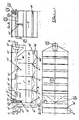
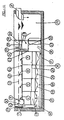
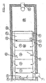
- the light liquid separator 1 shown in FIGS. 1a, b and c has an approximately rectangular housing into which a downwardly curved inlet 2 for a light liquid / heavy liquid mixture is introduced and an outlet 3 for the heavy liquid is led out at the other end of the separator.
- a sludge trap 5 In the longitudinal direction of the separator, it is divided from the inlet end into a sludge trap 5, a pre-separator space 6 and a residual separator space 7, the heavy liquid from the bottom of the residual separator space 7 via a riser 8, a corresponding overflow edge 21 and a small drain opening 22 provided in the associated overflow wall is led to the heavy liquid drain 4.
- the remaining separating space 7 is divided into two subchambers, each of which has an inclined plane inclined on both sides towards the center. In the middle of inclined plane there is a passage opening for the heavy liquid, which opens into the heavy liquid drain device.
- the remaining separation chamber 7 and the associated drainage device for the heavy liquid are separated from the pre-separation
- the sludge trap 5 and the pre-separation chamber 6 are separated from one another by a vertical partition 9. This partition extends up to slightly below the two-sided overflow edges 16 of the remaining separating space, which are described below.
- the remaining separation space 7 is in an “immersed” state in the pre-separation space 6, i. that is, it is surrounded both laterally and from the front and from below by the pre-separation chamber 6. Between the two longitudinal walls of the separator and the two lateral overflow walls of the residual separating space there are channel-shaped sections 20 of the preliminary separating space 6, via which liquid passes from the preliminary separating space 6 via the overflow edges 16 into the remaining separating space 7.
- a light liquid outlet 4 which has a light liquid inlet 10 in the form of a dip tube, a light liquid column expansion tank 11, a light liquid outlet 12 in the form of a riser pipe and a light liquid container 14 into which the riser pipe opens.
- the upper edge 18 of the light liquid inlet 10 (immersion tube) is located slightly below the overflow edges 16 of the side walls of the residual separation space 7.
- the length of the light liquid inlet 10 corresponds to the total height of the light liquid column above and below the heavy liquid level.
- the top edge 18 is like this arranged high above the heavy liquid level in retirement like the light liquid column above the heavy liquid level.
- the light liquid drain 4 further comprises a drain device in the form of a riser pipe 13, which opens directly into the light liquid container 14 and removes the light liquid layer pressed directly into the riser pipe 13. The light liquid is discharged from the light liquid container 14 via a pipe 15.
- the separator has a light liquid safety drain 19.
- a pressure compensation opening 17 is provided in the lower region of the light liquid column expansion tank 10, via which the light liquid column expansion tank 11 is connected to the front subchamber of the residual separation chamber 7.
- the mixture flowing in via the inlet 2 is deflected downwards into the sludge trap 5 and rises in the sludge trap along the partition 9 and flows over the partition 9 and reaches the pre-separating space 6 and fills it up. Liquid reaches the remaining separating space 7 via the overflow edges 16 on both sides, so that this is also filled up.
- the upper mirror shown in FIG. 1 a is set, which corresponds exactly to the height of the overflow edge 21 at the heavy liquid outlet.
- light liquid is already pressed into the light liquid container 14 via the riser pipe 13. If no further mixture flows in, the level gradually drops down to the lower edge of the small drain opening 22 at the heavy liquid outlet.
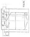
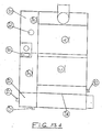
- This embodiment differs from that of FIG. 1 essentially in that the separator does not have a separate sludge trap, that the residual separator space from the pre-separator space is flown from both the front and the side and that the light liquid outlet has no additional riser pipe 13.
- the end wall 23 of the residual separating space 7 is angled in the upper area towards the heavy liquid drain, in order to obtain the largest possible area of non-displaceable heavy liquid level in the pre-separation chamber 6.
- the entire light liquid outlet 4 is arranged laterally next to the residual separating space 7, the light liquid column expansion tank 11 in the lower part of the separator extending essentially over its entire length.
- An area belonging to the pre-separation chamber 6 is located above the light liquid column expansion tank 11.
- the remaining separating space 7 has two overflow edges 16, namely a lateral and a forward-facing one, which is formed at the upper end of the end wall 23.
- the side of the pre-separator 6, arranged above the oil column expansion tank 11, ensures that the remaining separator 7 is flown over the corresponding overflow edge 16 not only from the front but also from the side when the mixture flows in.
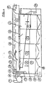
- the light liquid separator shown in FIGS. 3 to 5 is used, for example, to separate gasoline from water. It has a housing 1 ', which is approximately rectangular in plan view and can consist of steel or concrete, for example. At the right end of the separator in the figure 1 'there is an inlet 8' which is designed as a tube directed downwards into the separator. A corresponding heavy liquid drain 9 'is located at the opposite end of the separator. Behind the inlet 8 'there is an anteroom, which is completed by an inclined wall provided with an overflow edge. In this vestibule an inlet distribution 14 'is arranged.
- separating part chambers 15 ' In the flow direction behind the antechamber, four separating part chambers 15 'are provided, which extend over the entire width of the separator and are separated from one another by vertical walls 5', 6 'and 7'. An end wall 4 'limited the rearmost compartment in the flow direction.
- the respective subchambers have in their lower area a filled with packing space 17 '. The packing is held over gratings or wire mesh floors 20 'in the subchambers.
- At the lower end of the respective subchambers 19 'provided chamber floors are arranged as inclined planes. The inclined planes are inclined on both sides transversely to the flow direction of the separator towards the middle of the chamber and there have a heavy liquid discharge opening 18 'in the form of a gap which extends over the entire width of the chamber.
- the inclined levels 19' are arranged offset in height, namely to the heavy liquid drain towards higher and higher, so that below the heavy liquid drain towards heavy liquid drain channel is formed.
- This channel at the bottom of the cutter opens into a vertical shaft 16 ', which has an overflow edge 10' at its upper end. A certain distance below this overflow edge is a small outlet opening 11 '.
- the shaft opens into a heavy liquid drain shown at 9 '.
- the light liquid outlet is arranged in the area of the rearmost partial chamber in the flow direction and consists essentially of an upper retaining trough 21 ', a lower retaining trough 22', a light liquid outlet 23 'under the heavy liquid and two light liquid drains 24', 25 'above the heavy liquid.
- the process works such that when the heavy liquid level flows in over the overflow edge 10 ', the light liquid content is pressed via the light liquid discharge 24' into a storage container arranged outside the separator. At the same time, the light liquid in the lower retention trough 22 ' the drain pipe 25 'pressed into the storage container. When starting up, the light liquid runs out of both drain pipes 24 'and 25', during operation only from the drain pipe 25 '.
- the figure also shows at 12 'the heavy liquid level in the idle state and at 13' the heavy liquid level in operation.
- 27 'a ventilation pipe is indicated, at 26' a circulation pipe belonging to the light liquid outlet and at 28 'a drain pipe to the light liquid storage.
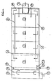
- FIGS. 6 to 8 the same parts as in the embodiment in FIGS. 1 to 3 are provided with the same reference symbols. Only different parts are described in the following explanation.
- the inlet 8 ' opens into an anteroom (inlet distribution) 14', which is closed by a wall provided with an overflow edge from the first sub-chamber.
- the heavy liquid / light liquid mixture in the vestibule can thus penetrate directly into the first partial chamber via the overflow edge.
- the corresponding wall is interrupted in its two lateral end areas. From the openings formed there are two inflow channels 30 'for the individual subchambers, the cross section of which narrows in the flow direction, which is achieved by a continuously increasing bottom wall.
- the two channels 30 ' end approximately in the middle the last subchamber and have an overflow edge towards the subchambers, through which heavy liquid can penetrate into the respective subchambers under the light liquid layer formed.
- the separator described above works in the following way.
- a heavy liquid-light liquid mixture is introduced via the inlet 8 'down into the vestibule 14' of the separator. It is assumed that the separator is already filled with liquid at this time. There is already a certain separation between light liquid and heavy liquid in the anteroom.
- the inflowing mixture is then deflected and flows upwards under the light liquid layer still present in the separator on the one hand directly into the first separating part chamber and on the other hand into the two inflow channels 30 'and from there into the further separating part chambers. This results in an increase in the light liquid layer, which in this way reaches the light liquid drain.
- the separating part chambers ensure a uniform passage in the vertical downward direction.
- the division into individual subchambers makes one essential better separation, ie higher efficiency, achieved than with a separator with only a single separation chamber with the same volume.
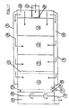
- FIG. 9 shows a plan view of a further embodiment of a separator, which differs from the embodiment of FIGS. 4 to 6 essentially only in that the inflow channels for the individual subchambers are arranged outside the actual separator housing. In this way, the partial chambers can be made correspondingly larger and have smooth side walls.
- the separator housing consisting of the several partial chambers is arranged in a larger space or a larger chamber 35 ′, which serves as a sludge trap.
- the inlet 8 ' does not open directly into the separator, but in the sludge trap.
- the inflowing mixture passes through a transverse wall through the sludge trap partition 33 ', which in this embodiment is the light liquid storage container, in the area of the separator and is there via channels remaining between the side walls of the separator and the sludge trap in the individual subchambers introduced, as in the embodiments described above, below a light liquid layer formed above.
- the light liquid drain with the corresponding devices is located in the flow direction in front of the first subchamber.
- the heavy liquid discharge channel located at the bottom 36 'of the separator housing in turn opens into a vertical shaft, the heavy liquid coming from there into a heavy liquid drain 9', which is designed as a pipe leaving the sludge trap.
- a heavy liquid drain 9' which is designed as a pipe leaving the sludge trap.
- this separator functions in the same way as the embodiments described above.
- the invention further proposes to divide the separation chamber into a plurality of subchambers arranged next to one another in the flow direction. Care is taken here that all subchambers are flowed evenly from the light liquid / heavy liquid mixture, for example via an overflow edge provided behind a prechamber.
- the partial chambers themselves have the same structure as in the embodiments described above.
- the heavy liquid outflow from the subchambers preferably takes place via drain openings provided centrally in the bottom of the chambers, which open into a common drainage channel which leads to the heavy liquid outflow.
- the light liquid drain is designed as in the aforementioned embodiments and is expediently provided in the center or in the corner areas of the separator.
- the subchambers have an upper end which lies below the heavy liquid level which forms in the idle state, so that a continuous light liquid layer is assigned to all subchambers.
- the non-displaceable water level is used for the oil drain instead of an oil retention trough.
- the lowering of the water level is throttled so that the oil layer largely still flows off with the oil layer of the area B shown in the figures can.
- a closed oil layer over the separation surface is better than none anyway. This keeps the fine oil droplets better.
- the non-displaceable water level use mentioned above is used instead of an oil retention trough.
- the areas B 'and B ⁇ were created by utilizing the oil column expansion tank and the oil storage tank, the surfaces of which serve as an oil retention basin, so to speak.
- the surface of the oil storage tank B ⁇ has an inclined plane as a slope to accelerate the oil drain in the direction B '. At the same time, an extended delay is achieved due to the deepest oil drain from surface C in direction B hunger.
- the non-displaceable water level is also used instead of an oil retention basin.
- the efficiency is increased by this advantageous arrangement. An oil drain without an upper retention trough is possible on the entire surface of the anteroom (oil drain area) with every retirement. There is only a small oil film in the separator area.
- the oil is diverted from the separator area to the oil drain area in every operating phase.
- the oil-free water level on the oil drain side is ready for use every time it is started up.
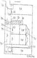
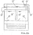
- Figure 14 1 ⁇ ⁇ inlet (with odor trap), 2 ⁇ ⁇ residual sludge (and heavy metal, flow brake, calming), 3 ⁇ ⁇ oil area (pre-separation and oil drainage), 4 ⁇ ⁇ separation chamber (outer walls with upper inlet edges ), 5 ⁇ ⁇ packing spaces, 6 ⁇ ⁇ inclined plane, 7 ⁇ ⁇ heavy liquid drain, 8 ⁇ ⁇ oil storage tank, 9 ⁇ ⁇ inlet to the oil storage tank, 10 ⁇ ⁇ oil suction opening, 11 ⁇ ⁇ oil intermediate tank, 12 ⁇ ⁇ oil circulation to the intermediate tank (emptied at each start-up), 13 ⁇ ⁇ oil drain to the oil storage tank, 14 ⁇ ⁇ oil drain during operation and 15 ⁇ ⁇ water level (water level fluctuations independent of passage).
- a overflow edge inlet there are three different water level heights in retirement: A overflow edge inlet, B oil inlet edge oil circulation pipe and C opening drain lock wall.
- the inlet edges / outer walls of the separator protrude above all water levels and thus prevent water from being displaced by the oil. Water can only be displaced in the separation chambers, which is why the intermediate container 11 ⁇ ⁇ is coupled to the level of these chambers.
- the oil layer flows through the oil circulation pipe 12 ⁇ ⁇ and rises to the surface of the water level C.
- the entire oil layer is pressed water-free into the oil storage tank by the inflowing water.
- An oil retention basin could only hold a part of this oil layer.
- the non-displaceable water level can also be used in large separators and compact systems with integrated sludge traps.
- the sludge trap surface serves as an oil retention basin.
Landscapes
- Physics & Mathematics (AREA)
- Thermal Sciences (AREA)
- Chemical & Material Sciences (AREA)
- Chemical Kinetics & Catalysis (AREA)
- Health & Medical Sciences (AREA)
- Life Sciences & Earth Sciences (AREA)
- Engineering & Computer Science (AREA)
- Hydrology & Water Resources (AREA)
- Public Health (AREA)
- Water Supply & Treatment (AREA)
- Removal Of Floating Material (AREA)
Priority Applications (1)
| Application Number | Priority Date | Filing Date | Title |
|---|---|---|---|
| AT88115636T ATE94080T1 (de) | 1987-09-24 | 1988-09-23 | Leichtfluessigkeitsabscheider. |
Applications Claiming Priority (4)
| Application Number | Priority Date | Filing Date | Title |
|---|---|---|---|
| DE3732136 | 1987-09-24 | ||
| DE3732136A DE3732136C2 (de) | 1987-09-24 | 1987-09-24 | Leichtflüssigkeitsabscheider |
| DE3812061A DE3812061C2 (de) | 1988-04-12 | 1988-04-12 | Leichtflüssigkeitsabscheider |
| DE3812061 | 1988-04-12 |
Publications (3)
| Publication Number | Publication Date |
|---|---|
| EP0308949A2 true EP0308949A2 (fr) | 1989-03-29 |
| EP0308949A3 EP0308949A3 (en) | 1989-08-23 |
| EP0308949B1 EP0308949B1 (fr) | 1993-09-08 |
Family
ID=25860090
Family Applications (1)
| Application Number | Title | Priority Date | Filing Date |
|---|---|---|---|
| EP88115636A Expired - Lifetime EP0308949B1 (fr) | 1987-09-24 | 1988-09-23 | Séparateur de liquides légers |
Country Status (2)
| Country | Link |
|---|---|
| EP (1) | EP0308949B1 (fr) |
| DE (1) | DE3883903D1 (fr) |
Cited By (7)
| Publication number | Priority date | Publication date | Assignee | Title |
|---|---|---|---|---|
| DE3918343A1 (de) * | 1989-06-06 | 1990-12-13 | Nikolaus Hammerschmitt | Leichtfluessigkeitsabscheider |
| DE3930226A1 (de) * | 1989-07-26 | 1991-01-31 | Nikolaus Hammerschmitt | Leichtfluessigkeitsabscheider mit vorabscheideraum |
| US5108609A (en) * | 1989-08-11 | 1992-04-28 | Burt Separators Limited | Treatment of liquids |
| EP0692290A1 (fr) * | 1994-07-13 | 1996-01-17 | Nikolaus Hammerschmitt | Séparateur de graisses et de liquides légers |
| ES2102323A1 (es) * | 1995-07-25 | 1997-07-16 | Pons Gabriel Vives | Depuradora sencilla de aguas residuales. |
| EP1386650A3 (fr) * | 2002-07-31 | 2004-04-28 | Aco Severin Ahlmann GmbH & Co. KG | Dispositif pour séparer une phase plus légère d'une eau usée. |
| CN107875678A (zh) * | 2017-09-22 | 2018-04-06 | 广东林顿重工股份有限公司 | 一种溶剂分离装置 |
Families Citing this family (1)
| Publication number | Priority date | Publication date | Assignee | Title |
|---|---|---|---|---|
| EP1926688A1 (fr) * | 2005-06-01 | 2008-06-04 | Cumminscorp Limited | Unite modulaire de traitement de l'eau |
Family Cites Families (4)
| Publication number | Priority date | Publication date | Assignee | Title |
|---|---|---|---|---|
| US4111805A (en) * | 1976-08-16 | 1978-09-05 | Phillips Petroleum Company | Separation of solvent from liquid sulfur |
| DE3303632A1 (de) * | 1983-02-03 | 1984-08-09 | Nikolaus 5350 Euskirchen Hammerschmitt | Leichtfluessigkeitsabscheider |
| DE3516895A1 (de) * | 1985-05-10 | 1986-11-13 | Nikolaus 5350 Euskirchen Hammerschmitt | Leichtfluessigkeitsabscheider |
| DE8600285U1 (de) * | 1986-01-08 | 1986-12-04 | RMC, Rodenberg, Marketing, Engineering und Consulting GmbH, 6452 Hainburg | Abscheider für Fette aus Wässern |
-
1988
- 1988-09-23 EP EP88115636A patent/EP0308949B1/fr not_active Expired - Lifetime
- 1988-09-23 DE DE88115636T patent/DE3883903D1/de not_active Expired - Fee Related
Cited By (9)
| Publication number | Priority date | Publication date | Assignee | Title |
|---|---|---|---|---|
| DE3918343A1 (de) * | 1989-06-06 | 1990-12-13 | Nikolaus Hammerschmitt | Leichtfluessigkeitsabscheider |
| WO1990014874A1 (fr) * | 1989-06-06 | 1990-12-13 | Nikolaus Hammerschmitt | Separateur de liquides legers |
| US5151185A (en) * | 1989-06-06 | 1992-09-29 | Nikolaus Hammerschmitt | Light-liquid separator |
| DE3930226A1 (de) * | 1989-07-26 | 1991-01-31 | Nikolaus Hammerschmitt | Leichtfluessigkeitsabscheider mit vorabscheideraum |
| US5108609A (en) * | 1989-08-11 | 1992-04-28 | Burt Separators Limited | Treatment of liquids |
| EP0692290A1 (fr) * | 1994-07-13 | 1996-01-17 | Nikolaus Hammerschmitt | Séparateur de graisses et de liquides légers |
| ES2102323A1 (es) * | 1995-07-25 | 1997-07-16 | Pons Gabriel Vives | Depuradora sencilla de aguas residuales. |
| EP1386650A3 (fr) * | 2002-07-31 | 2004-04-28 | Aco Severin Ahlmann GmbH & Co. KG | Dispositif pour séparer une phase plus légère d'une eau usée. |
| CN107875678A (zh) * | 2017-09-22 | 2018-04-06 | 广东林顿重工股份有限公司 | 一种溶剂分离装置 |
Also Published As
| Publication number | Publication date |
|---|---|
| DE3883903D1 (de) | 1993-10-14 |
| EP0308949B1 (fr) | 1993-09-08 |
| EP0308949A3 (en) | 1989-08-23 |
Similar Documents
| Publication | Publication Date | Title |
|---|---|---|
| EP0429593B1 (fr) | Separateur de liquides legers | |
| EP0201072B1 (fr) | Separateur de liquides légers | |
| EP0118021B1 (fr) | Séparateur de liquides légers | |
| EP0037855A1 (fr) | Procédé et dispositif pour la séparation continue des composants d'un mélange de liquides de poids spécifiques différents | |
| EP0308949B1 (fr) | Séparateur de liquides légers | |
| DE2837554C2 (de) | Leichtflüssigkeitsabscheider | |
| EP0069885A1 (fr) | Filtre à action séparatrice pour purifier de l'eau contaminée par un liquide léger tel qu'huile ou essence | |
| DE8915490U1 (de) | Flüssigkeitsabscheider | |
| EP0228520B1 (fr) | Séparateur, en particulier pour graisse de l'eau | |
| DE1936350A1 (de) | Vorrichtung zum Trennen von Gasen und Fluessigkeiten,insbesondere zur Entgasung von Kohlenwasserstoffen | |
| DE3014204A1 (de) | Verfahren und vorrichtung zum trennen oder abziehen eines gemisches aus leicht-, schwerfluessigkeit und ggf. schlamm | |
| DE2136397C3 (de) | Phasenscheider für Flüssig-Flüssig- Extraktoren | |
| EP0096825B1 (fr) | Dispositif pour la purification anaérobie d'eau usée | |
| DE2627598C2 (de) | Vorrichtung zum Abscheiden und Rückhalten nichtgelöster Kohlenwasserstoffe aus Wasser | |
| AT400948B (de) | Vorrichtung zum trennen von miteinander nicht mischbaren flüssigkeiten | |
| DE3732136C2 (de) | Leichtflüssigkeitsabscheider | |
| DE3812061C2 (de) | Leichtflüssigkeitsabscheider | |
| DE1912584A1 (de) | Vorrichtung zum Behandeln von Abwasser od.dgl. | |
| DE3930226C2 (fr) | ||
| DE8121718U1 (de) | Vorrichtung zum trennen zweier fluessigkeiten unterschiedlicher dichte | |
| DE2951205C2 (de) | Leichtflüssigkeitsabscheider | |
| WO1998024530A1 (fr) | Bassin de decantation de forme rectangulaire pour la separation de la boue contenue dans des eaux usees | |
| AT508656B1 (de) | Abscheider | |
| WO1996004057A1 (fr) | Separateur de matieres legeres organiques entrainees dans des eaux usees | |
| DE3023384A1 (de) | Vorrichtung zur trennung von leicht- und schwerfluessigkeit und gegebenenfalls schlamm |
Legal Events
| Date | Code | Title | Description |
|---|---|---|---|
| PUAI | Public reference made under article 153(3) epc to a published international application that has entered the european phase |
Free format text: ORIGINAL CODE: 0009012 |
|
| AK | Designated contracting states |
Kind code of ref document: A2 Designated state(s): AT BE CH DE ES FR GB GR IT LI LU NL SE |
|
| PUAL | Search report despatched |
Free format text: ORIGINAL CODE: 0009013 |
|
| AK | Designated contracting states |
Kind code of ref document: A3 Designated state(s): AT BE CH DE ES FR GB GR IT LI LU NL SE |
|
| 17P | Request for examination filed |
Effective date: 19891222 |
|
| RAP1 | Party data changed (applicant data changed or rights of an application transferred) |
Owner name: PROGRESS AG Owner name: HAMMERSCHMITT, NIKOLAUS |
|
| RIN1 | Information on inventor provided before grant (corrected) |
Inventor name: HAMMERSCHMITT, NIKOLAUS |
|
| 17Q | First examination report despatched |
Effective date: 19910916 |
|
| GRAA | (expected) grant |
Free format text: ORIGINAL CODE: 0009210 |
|
| AK | Designated contracting states |
Kind code of ref document: B1 Designated state(s): AT BE CH DE ES FR GB GR IT LI LU NL SE |
|
| PG25 | Lapsed in a contracting state [announced via postgrant information from national office to epo] |
Ref country code: SE Effective date: 19930908 Ref country code: GR Free format text: LAPSE BECAUSE OF FAILURE TO SUBMIT A TRANSLATION OF THE DESCRIPTION OR TO PAY THE FEE WITHIN THE PRESCRIBED TIME-LIMIT Effective date: 19930908 Ref country code: GB Effective date: 19930908 Ref country code: FR Effective date: 19930908 Ref country code: ES Free format text: THE PATENT HAS BEEN ANNULLED BY A DECISION OF A NATIONAL AUTHORITY Effective date: 19930908 |
|
| REF | Corresponds to: |
Ref document number: 94080 Country of ref document: AT Date of ref document: 19930915 Kind code of ref document: T |
|
| PG25 | Lapsed in a contracting state [announced via postgrant information from national office to epo] |
Ref country code: AT Effective date: 19930923 |
|
| PG25 | Lapsed in a contracting state [announced via postgrant information from national office to epo] |
Ref country code: LI Effective date: 19930930 Ref country code: CH Effective date: 19930930 |
|
| REF | Corresponds to: |
Ref document number: 3883903 Country of ref document: DE Date of ref document: 19931014 |
|
| ITF | It: translation for a ep patent filed | ||
| EN | Fr: translation not filed | ||
| EPTA | Lu: last paid annual fee | ||
| GBV | Gb: ep patent (uk) treated as always having been void in accordance with gb section 77(7)/1977 [no translation filed] |
Effective date: 19930908 |
|
| REG | Reference to a national code |
Ref country code: CH Ref legal event code: PL |
|
| PLBE | No opposition filed within time limit |
Free format text: ORIGINAL CODE: 0009261 |
|
| STAA | Information on the status of an ep patent application or granted ep patent |
Free format text: STATUS: NO OPPOSITION FILED WITHIN TIME LIMIT |
|
| 26N | No opposition filed | ||
| PGFP | Annual fee paid to national office [announced via postgrant information from national office to epo] |
Ref country code: LU Payment date: 19960901 Year of fee payment: 9 |
|
| PGFP | Annual fee paid to national office [announced via postgrant information from national office to epo] |
Ref country code: NL Payment date: 19960930 Year of fee payment: 9 |
|
| PGFP | Annual fee paid to national office [announced via postgrant information from national office to epo] |
Ref country code: BE Payment date: 19961011 Year of fee payment: 9 |
|
| PG25 | Lapsed in a contracting state [announced via postgrant information from national office to epo] |
Ref country code: LU Free format text: LAPSE BECAUSE OF NON-PAYMENT OF DUE FEES Effective date: 19970923 |
|
| PG25 | Lapsed in a contracting state [announced via postgrant information from national office to epo] |
Ref country code: BE Free format text: LAPSE BECAUSE OF NON-PAYMENT OF DUE FEES Effective date: 19970930 |
|
| BERE | Be: lapsed |
Owner name: HAMMERSCHMITT NIKOLAUS Effective date: 19970930 |
|
| PG25 | Lapsed in a contracting state [announced via postgrant information from national office to epo] |
Ref country code: NL Free format text: LAPSE BECAUSE OF NON-PAYMENT OF DUE FEES Effective date: 19980401 |
|
| NLV4 | Nl: lapsed or anulled due to non-payment of the annual fee |
Effective date: 19980401 |
|
| PGFP | Annual fee paid to national office [announced via postgrant information from national office to epo] |
Ref country code: DE Payment date: 20001120 Year of fee payment: 13 |
|
| PG25 | Lapsed in a contracting state [announced via postgrant information from national office to epo] |
Ref country code: DE Free format text: LAPSE BECAUSE OF NON-PAYMENT OF DUE FEES Effective date: 20020501 |
|
| PG25 | Lapsed in a contracting state [announced via postgrant information from national office to epo] |
Ref country code: IT Free format text: LAPSE BECAUSE OF NON-PAYMENT OF DUE FEES Effective date: 20050923 |