EP0309044A1 - Dispositif de commande pour carburateur à gaz du type à Venturi - Google Patents
Dispositif de commande pour carburateur à gaz du type à Venturi Download PDFInfo
- Publication number
- EP0309044A1 EP0309044A1 EP88202012A EP88202012A EP0309044A1 EP 0309044 A1 EP0309044 A1 EP 0309044A1 EP 88202012 A EP88202012 A EP 88202012A EP 88202012 A EP88202012 A EP 88202012A EP 0309044 A1 EP0309044 A1 EP 0309044A1
- Authority
- EP
- European Patent Office
- Prior art keywords
- gas
- chamber
- pipe
- pressure
- control
- Prior art date
- Legal status (The legal status is an assumption and is not a legal conclusion. Google has not performed a legal analysis and makes no representation as to the accuracy of the status listed.)
- Granted
Links
- 230000001105 regulatory effect Effects 0.000 title claims abstract description 40
- 239000000203 mixture Substances 0.000 claims abstract description 40
- 239000000523 sample Substances 0.000 claims abstract description 13
- 238000002485 combustion reaction Methods 0.000 claims abstract description 8
- 239000012528 membrane Substances 0.000 claims description 38
- 230000009183 running Effects 0.000 claims description 17
- 239000000446 fuel Substances 0.000 claims description 14
- 238000011144 upstream manufacturing Methods 0.000 claims description 13
- 208000036366 Sensation of pressure Diseases 0.000 claims description 10
- 230000035939 shock Effects 0.000 claims description 3
- 239000007858 starting material Substances 0.000 claims description 3
- ZMJBYMUCKBYSCP-UHFFFAOYSA-N Hydroxycitric acid Chemical compound OC(=O)C(O)C(O)(C(O)=O)CC(O)=O ZMJBYMUCKBYSCP-UHFFFAOYSA-N 0.000 claims 1
- 239000007789 gas Substances 0.000 abstract description 138
- 239000002737 fuel gas Substances 0.000 abstract description 3
- 239000003570 air Substances 0.000 description 34
- 238000002156 mixing Methods 0.000 description 15
- MWUXSHHQAYIFBG-UHFFFAOYSA-N nitrogen oxide Inorganic materials O=[N] MWUXSHHQAYIFBG-UHFFFAOYSA-N 0.000 description 13
- 230000000694 effects Effects 0.000 description 8
- 238000006073 displacement reaction Methods 0.000 description 4
- 238000009434 installation Methods 0.000 description 4
- VNWKTOKETHGBQD-UHFFFAOYSA-N methane Chemical compound C VNWKTOKETHGBQD-UHFFFAOYSA-N 0.000 description 4
- 230000001133 acceleration Effects 0.000 description 3
- 230000033228 biological regulation Effects 0.000 description 3
- 238000004891 communication Methods 0.000 description 3
- 238000010276 construction Methods 0.000 description 3
- 230000004075 alteration Effects 0.000 description 2
- 230000008901 benefit Effects 0.000 description 2
- 230000008878 coupling Effects 0.000 description 2
- 238000010168 coupling process Methods 0.000 description 2
- 238000005859 coupling reaction Methods 0.000 description 2
- 230000001419 dependent effect Effects 0.000 description 2
- 238000010586 diagram Methods 0.000 description 2
- 239000008240 homogeneous mixture Substances 0.000 description 2
- 230000001788 irregular Effects 0.000 description 2
- 238000004519 manufacturing process Methods 0.000 description 2
- 239000000463 material Substances 0.000 description 2
- 238000000034 method Methods 0.000 description 2
- 239000003345 natural gas Substances 0.000 description 2
- 229910052757 nitrogen Inorganic materials 0.000 description 2
- 235000019755 Starter Diet Nutrition 0.000 description 1
- 230000009471 action Effects 0.000 description 1
- 230000002730 additional effect Effects 0.000 description 1
- 239000012080 ambient air Substances 0.000 description 1
- 230000009286 beneficial effect Effects 0.000 description 1
- 230000001609 comparable effect Effects 0.000 description 1
- 230000006835 compression Effects 0.000 description 1
- 238000007906 compression Methods 0.000 description 1
- KAATUXNTWXVJKI-UHFFFAOYSA-N cypermethrin Chemical compound CC1(C)C(C=C(Cl)Cl)C1C(=O)OC(C#N)C1=CC=CC(OC=2C=CC=CC=2)=C1 KAATUXNTWXVJKI-UHFFFAOYSA-N 0.000 description 1
- 230000003247 decreasing effect Effects 0.000 description 1
- 230000003111 delayed effect Effects 0.000 description 1
- 238000010304 firing Methods 0.000 description 1
- -1 for example Substances 0.000 description 1
- 238000003754 machining Methods 0.000 description 1
- 239000002184 metal Substances 0.000 description 1
- 229940093652 prevail Drugs 0.000 description 1
- 230000008569 process Effects 0.000 description 1
Images




Classifications
-
- F—MECHANICAL ENGINEERING; LIGHTING; HEATING; WEAPONS; BLASTING
- F02—COMBUSTION ENGINES; HOT-GAS OR COMBUSTION-PRODUCT ENGINE PLANTS
- F02M—SUPPLYING COMBUSTION ENGINES IN GENERAL WITH COMBUSTIBLE MIXTURES OR CONSTITUENTS THEREOF
- F02M21/00—Apparatus for supplying engines with non-liquid fuels, e.g. gaseous fuels stored in liquid form
- F02M21/02—Apparatus for supplying engines with non-liquid fuels, e.g. gaseous fuels stored in liquid form for gaseous fuels
- F02M21/04—Gas-air mixing apparatus
- F02M21/047—Venturi mixer
-
- F—MECHANICAL ENGINEERING; LIGHTING; HEATING; WEAPONS; BLASTING
- F02—COMBUSTION ENGINES; HOT-GAS OR COMBUSTION-PRODUCT ENGINE PLANTS
- F02M—SUPPLYING COMBUSTION ENGINES IN GENERAL WITH COMBUSTIBLE MIXTURES OR CONSTITUENTS THEREOF
- F02M21/00—Apparatus for supplying engines with non-liquid fuels, e.g. gaseous fuels stored in liquid form
- F02M21/02—Apparatus for supplying engines with non-liquid fuels, e.g. gaseous fuels stored in liquid form for gaseous fuels
- F02M21/0218—Details on the gaseous fuel supply system, e.g. tanks, valves, pipes, pumps, rails, injectors or mixers
- F02M21/023—Valves; Pressure or flow regulators in the fuel supply or return system
- F02M21/0239—Pressure or flow regulators therefor
-
- F—MECHANICAL ENGINEERING; LIGHTING; HEATING; WEAPONS; BLASTING
- F02—COMBUSTION ENGINES; HOT-GAS OR COMBUSTION-PRODUCT ENGINE PLANTS
- F02M—SUPPLYING COMBUSTION ENGINES IN GENERAL WITH COMBUSTIBLE MIXTURES OR CONSTITUENTS THEREOF
- F02M21/00—Apparatus for supplying engines with non-liquid fuels, e.g. gaseous fuels stored in liquid form
- F02M21/02—Apparatus for supplying engines with non-liquid fuels, e.g. gaseous fuels stored in liquid form for gaseous fuels
- F02M21/04—Gas-air mixing apparatus
- F02M21/042—Mixer comprising a plurality of bores or flow passages
-
- Y—GENERAL TAGGING OF NEW TECHNOLOGICAL DEVELOPMENTS; GENERAL TAGGING OF CROSS-SECTIONAL TECHNOLOGIES SPANNING OVER SEVERAL SECTIONS OF THE IPC; TECHNICAL SUBJECTS COVERED BY FORMER USPC CROSS-REFERENCE ART COLLECTIONS [XRACs] AND DIGESTS
- Y02—TECHNOLOGIES OR APPLICATIONS FOR MITIGATION OR ADAPTATION AGAINST CLIMATE CHANGE
- Y02T—CLIMATE CHANGE MITIGATION TECHNOLOGIES RELATED TO TRANSPORTATION
- Y02T10/00—Road transport of goods or passengers
- Y02T10/10—Internal combustion engine [ICE] based vehicles
- Y02T10/30—Use of alternative fuels, e.g. biofuels
Definitions
- the invention relates to a regulating device for a venturi-type gas carburettor, in particular for internal combustion engines, comprising: - a low-pressure regulator of the zero-pressure type, which is sited in the gas pipe system between a gas source at a pressure of between about 0.1 and 1.0 bar and an annular chamber around the venturi, having a housing with two enclosed spaces essentially separated from each other, a regulating membrane being fitted in one space, as a result of which two chambers are formed, the chamber on the one side of the membrane being connected to a reference pressure and the other chamber being connected to a regulating or control pressure, and the other space containing the gas inlet valve and the gas outlet (outlet chamber), and the housing being provided with a low-friction, gas-tight duct to the other space for a regulating rod connected to the membrane, which rod operates the gas inlet valve, if necessary via suitable means, such as levers, - a gas pipe which connects the gas outlet of the low-pressure
- a venturi-type gas carburettor is known from European Patent Application 85.200.726.9.
- a low pressure regulator of the zero pressure type is known inter alia from Dutch Disclosure 177,142. It may also be noted that the low-pressure regulator described and depicted in the lastmentioned publication is of the type which is not very sensitive to movements and accelerations and descellerations acting on the regulator. It is intended in particular for use in road vehicles. In this case the dimensions of the gas inlet are relatively small because in general relatively rich gases, such as natural gas or LPG vapour, are used.
- the invention relates equally to low-pressure regulators of the zero-pressure type which are designed for stationary installation, the gas inlet valve usually being of larger dimensions and being balanced.
- the type of low-pressure regulator of the zero-pressure type involved is generally suitable for a relatively low inlet pressure in the order of magnitude of 0.1 to 1.0 bar.
- An essential characteristic is that regardless of the offtake, the pressure regulator always strives to maintain a pressure at its outlet equal to the pressure which acts on the reference side of the membrane. This is usually the ambient pressure, although it may also be the pressure after an air filter if used in internal combustion engines. It essentially makes no difference to the present invention which type of zero-pressure regulator is used: the type for mobile installation, the type for stationary installation or yet other types.
- Such a system comprising the low-pressure regulator and the gas carburettor will have to be able to deliver the desired air/gas mixture to the engine over its entire power and speed range.
- the throat of the venturi in such a gas carburettor is, in general, relatively narrow. For higher engine loads, this means a not inconsiderable throttling which reaches its highest value just when the main throttle valve of the engine is opened completely.
- a venturi with higher suction force that is, a venturi with smaller throat
- has other disadvantages such as a greater pressure loss, a lower filling rate of the engine, an excessively high resistance in engines with turbo-supercharging, which may even result in damage to the compressor, and interference with any petrol carburettor present if the system is used in petrol/gas engines.
- a mixing and regulating device with a still lower resistance but nevertheless a good air/gas mixing and the possibility of being able to influence the air/fuel ratio independently of load. This latter applies in particular to partial loading of the engines.
- said objects are met by the regulating device described in the introduction in that any connection is absent in the pressure regulator between the outlet space and the control chamber of the membrane, and in that the control chamber of the membrane is connected both via a first control pipe to the annular chamber around the venturi and via a second control pipe to a probe which projects into the throat of the venturi.
- the throat of the venturi can be appreciably enlarged without an inadequate control signal going from the venturi to the pressure regulators.
- virtually the same pressure exists in the annular chamber around the venturi as in the outlet chamber of the pressure regulator so that the venturi has to be relatively narrow in order to feed an adequately large signal to the membrane of the pressure regulator.
- the pressure difference between the throat of the venturi and the reference pressure prevails virtually entirely across the gas supply openings or the gas supply slot of the venturi so that virtually the same pressure prevails in the annular chamber of the venturi as in the outlet chamber of the pressure regulator.
- a separate probe which projects into the throat of the venturi is used to obtain a pressure signal which is the lowest which exists in the venturi.
- the wall effects due to air flow along the wall of the venturi are excluded by arranging for the probe to project.
- virtually no flow takes place in the probe and it is also not used for the gas supply.
- the zero-pressure regulator will no longer be able to operate as a pure zero-pressure regulator; it is overdriven.
- the membrane is loaded with a signal which is between the greatest under pressure in the throat of the venturi and the pressure in the annular chamber. Thanks to the gas supply, a higher pressure always prevails in the annular chamber, at least when the engine is running, than is measured by the probe. A flow therefore takes place through both control pipes, and to be specific, from the first to the second control pipe. Since signals are involved here and not large mass flows, the control pipes may be narrow and the flow rate is low.
- the gas supply openings or the gas supply slot remain approximately the same. Since, however, the gas supply pressure is somewhat higher in an absolute sense, the gas supply openings or the slot can be slightly smaller, as a result of which the flow rate of the gas through the supply openings increases. These gas flows with greater speed meet an air flow with lower speed (thanks to the wider venturi throat) so that the gas can penetrate further into the air flow and a better homogeneous mixture is delivered, even after the first mixing of the gas with the air.
- the gas pressure difference between the annular chamber and the throat of the venturi will remain approximately the same, despite the larger inside width of the venturi. Because the gas is now supplied, according to the invention, with an over pressure, the gas supply pipe between the gas pressure regulator and the carburettor can be smaller, and in practice this is a great advantage. Furthermore, in many cases the large main adjustment screw can be omitted because it is possible, according to a preferred embodiment of the invention, to incorporate one adjustable throttle device each both in the first and the second control pipes. These throttling devices can be used to adjust the maximum quantity of gas to be delivered by the pressure regulator, in a manner comparable to that which was applied in the known systems with the main adjustment screw.
- the referencepressure side of the membrane always remains under the influence of the reference pressure so that an identical pressure is established on the control chamber side of the membrane in a stable equilibrium situation.
- the regulator continues to operate as a zero-pressure regulator.
- the gas pressure delivered will have to be higher than the reference pressure by the same amount as the underpressure measured by the probe in the throat of the venturi is lower than the reference pressure. Consequently, as a result of the pressure division which is produced with equivalent first and second control pipes on the control side of the membrane, a pressure equal to the reference pressure will be delivered.
- the throttling devices in the first and second control pipe are differently adjusted, adjustment will be made to a higher or lower outlet pressure by the pressure regulator.
- the air/fuel ratio delivered by the mixing device can thereby be adjusted.
- the pressure division of the first control signal and the second control signal is no longer proportional under these circumstances and in this manner, the combination of the two throttling devices, which are each separately adjustable, is able to form a pneumatic potentiometer.
- the latter can be adjusted once so as thereby to achieve a fixed adjustment of the air/fuel ratio as the latter is delivered by the mixing device.
- Said pneumatic potentiometer consequently fulfills the function of the known main adjustment screw, which can therefore be omitted, as was already stated earlier.
- the pneumatic potentiometer with a fixed adjustment but to allow it to be controlled as a function of the engine load.
- a loaddependent air-fuel regulation can be achieved in a simple manner.
- One possibility in this connection is to couple the two throttling devices to the position of the main throttle valve of the engine. In this case it is attractive to open one throttling device to the same extent as the other is closed and to do this as a function of the position of the main throttle valve, for example by mounting a cam disc thereon which controls the potentiometer via a following device.
- an increasing under pressure prevails down stream of the main throttle valve at lower loads and at no-load as a result of increasing throttling.
- a number of preferred embodiments make use of this variable throttling downstream of the throttle valve in order to thereby establish a load-dependent air/fuel ratio in a different manner. If said underpressure is fed to the reference chamber of the membrane via a pneumatic potentiometer, this will cause an enleanment of the air/fuel mixture at partial load. If, on the other hand, said under pressure is fed to the control side via the pneumatic potentiometer, this will be capable of providing an enrichment at partial load. It is furthermore possible to facilitate the starting of the engine by temporarily feeding some or all of the vacuum to the control chamber at the same time as the starter motor is energized in order to temporarily enrich the starting mixture which is drawn in by the engine.
- the main throttle valve is sited in the air intake pipe of the engine downstream with respect to the gas carburettor.
- the majority of the accompanying illustrations relate to this embodiment.
- venturi gas carburettors which are sited downstream with respect to the main throttle valve.
- An example is depicted for the purpose of illustration and briefly explained.
- the supercharging compressor if present, may be sited either downstream or upstream with respect to the gas carburettor but virtually exclusively upstream with respect to the throttle valve in order not to disturb the operation of the compressor or even to avoid compressor damage. All these alternatives fall essentially within the invention, but they cannot all be discussed. The examples are limited to the embodiments which occur most often.
- FIGs 1 to 5 incl. all relate to systems which most often occur in practice in which the gas carburettor is sited upstream with respect to the main throttle valve.
- Figure 1 depicts the regulating device according to the invention in its basic embodiment, a small number of specific preferred embodiments also being depicted.
- the regulating device comprises essentially the gas mixing device 1, the gas pressure regulator 20, the gas supply pipe 13 and the regulating means 50 in conjunction with the associated pipes.
- the majority of the parts depicted is shown only diagrammatically.
- the engine which is not shown, draws in an air/fuel mixture via the suction pipe 2 as indicated by the arrow 7. Ambient air is drawn in via the diagrammatically shown air filter 3 as indicated by the arrow 4.
- the main throttle valve 6, with which the power to be delivered by the engine, or at constant speed, the load, is adjusted is sited upstream of the engine as the final important element in the suction pipe 2. If the engine concerned is a petrol/gas engine, the main throttle valve 6 is sited in a petrol carburettor which is not shown. If the engine is equipped with supercharging, the supercharging compressor 8 is generally sited upstream with respect to the main throttle valve 6 and this is shown diagrammatically in Figure 1. Any postcooler used is generally sited immediately downstream of the compressor 8.
- the gas/air mixing device 1 in virtually all cases forms a separated unit which is mounted on the suction pipe 2.
- the narrowest inside width of the venturi is formed by the throat 10 which, according to the present invention, is of relatively large diameter in order to provide a minimum of suction resistance for the engine.
- the so-called annular chamber 11 Situated around the venturi is the so-called annular chamber 11 to which the fuel gas is supplied via a pipe 13.
- openings 12 are provided for transferring gas from the annular chamber 11 to the air stream 4 which flows through the throat 10 of the venturi.
- annular slot may also be used.
- an annular slot provides a larger inside width, in general the mixing of the gas with the air in the case of an annular slot is less satisfactory than if separate supply openings 12 are used.
- a narrow pipe 14 is depicted which is connected upstream of the venturi and downstream of the air filter 3, which pipe 14 feeds the pressure prevailing immediately upstream the venturi, the so-called reference pressure, to the pressure regulator 20.
- a pressure lower than the ambient pressure prevails in the reference pipe 14 because, when the engine is running, the air filter 3 has a certain flow resistance.
- a pipe 15 is likewise connected in a known manner to the annular chamber 11 of the mixing device 1, which pipe feeds a pressure signal to the gas pressure regulator 20. In view of its function, the pipe 15 is termed the first control pipe.
- the second essential component of the regulating device is formed by the gas pressure regulator 20, which is a so-called low-pressure regulator of the zero-pressure type.
- the regulator depicted is one of the type which is nevertheless capable of continuing to function well despite any accelerations and decelerations acting thereon. It is therefore usable in, for example, road vehicles. All the functional characteristics which will be discussed below, apply, however, to an equal extent to the generally known zero-pressure regulators of the stationary type which are mounted in a fixed position and are not suitable for subjection to accelerations and decelerations during operation.
- the regulator is per se of a known type and is formed by a housing having two spaces 27/28 and 29 respectively, separated from each other.
- the walls 21 and 22 form a space in which the regulating membrane 23 is situated.
- the membrane 23 is clamped in a gas tight manner over its circumference at 24 between the walls 21 and 22, as is indicated diagrammatically by the dotted lines for the fixing bolts.
- two chambers are formed in the space; the uppermost chamber 27 forms the reference chamber because it is connected to the reference pipe 14 via the connection 38.
- the same pressure always therefore prevails in the reference chamber 27 as immediately upstream the mixing device 1.
- the other chamber 28 which is acted on by the control pressure. This is dealt with in more detail below. Any displacements of the membrane as a result of a pressure difference between the chambers 27 and 28 is passed on via a rod 26.
- support plates 25 are fitted in the usual manner below and above the membrane and these are usually manufactured from thin and light metal or plastic.
- the rod 26 is attached to these plates.
- the rod 26 is passed through the wall 22 with as little friction as possible, but with low leakage, in order to operate the gas supply valve 31 - 33 via a lever 34.
- the bottom of the pin 26 rests in a recess 37 of the lever 34.
- the lever 34 can be pivoted with low friction around a pivot shaft 35 attached to the housing. Attached to the lever 34 at the other side of the pivot shaft is a valve 33, for example, manufactured from rubber or a similar material which interacts with the discharge end 31 of the gas supply pipe 32.
- the gas is supplied to the pipe 32 at a pressure of approximately 0.3 bar from a gas source and the pressure may have been reduced previously to approximately the said value. If the membrane 23 moves downwards as a result of decreasing pressure in the control chamber 28, the pin 26 forces the lever 34 in an anticlockwise direction, as a result of which the discharge opening 31/33 is opened further, with the result that more gas is allowed into the discharge chamber 29.
- Said chamber is in open communication with the gas pipe 13 which leads to the gas carburettor 1.
- the gas pipe 13 is usually formed by a hose pipe of appreciable dimensions in order to keep the flow resistance therein as low as possible.
- a spring 36 which is shown diagrammatically and may be adjustable, presses with a low force against the lever 34 in order to compensate both for the weight of the plate 25, the rod 26 and, if necessary, of the lever 34, but also for the gas pressure exerted on the corresponding surface of the valve 33.
- these components are usually replaced by a valve with a much greater clear passage which is balanced to compensate for the gas pressure acting thereon by a small membrane which serves as a replacement for the lowfriction, leak-free passage, shown in Figure 1, for the pin 26 through the wall 22.
- the known pressure regulators to be set up in a fixed position and of the zero-pressure type are functionally identical to the regulators described above.
- control chamber 28 has a connection 39 for the control pipe 53.
- the control pipe 53 forms the connection between the pressure regulator 20 and the pneumatic potentiometer which is shown diagrammatically by 50.
- the first control line 15 running from the annular chamber 11 of the gas carburettor to the potentiometer 50 incorporates an adjustable throttle device 54.
- second control pipe 51 From a probe 52 which projects into the throat 10 of the venturi 9, there runs a second control pipe 51, also to the potentiometer 50, which likewise contains an adjustable throttling device 55.
- the two throttling devices 54 and 55 are connected to each other via a pipe to which the control pipe 53 running to the pressure regulator 20 is connected.
- a lower pressure will always prevail via the probe 52 in the second control pipe 51 than in the first control pipe 15 connected to the annular chamber 11 so that some flow as indicated by the arrows shown will always take place.
- adjusting the throttling devices 54 and 55 serves a purpose because the pressure in the pipe 53 can, as a result, be adjusted between the pressure in the first control pipe 15 or in the second control pipe 51 as extreme values, according to whether the throttling device 55 or the throttling device 54 respectively is completely closed. If the two throttling devices are identically adjusted and the control pipes 50 and 51 have an identical resistance, precisely the average of the pressure in the first control pipe 15 and in the second control pipe 51 will prevail in the pipe 53.
- the gas pressure delivered by the zero-pressure regulator 21 in the pipe 13 will have a value precisely equal to the average pressure between the reference pressure in the pipe 14 and the under pressure in the throat 10 as measured by the probe 52. It should be pointed out in this connection that the zero-pressure regulator continues to regulate as a zero-pressure regulator since the position of the membrane 23 is always such that the pressure in the control chamber 28 is equal to that in the reference chamber 27. Under these circumstances, the pressure in the control pipe 53 will likewise have to be equal to that in the reference pipe 14. The gas pressure in the outlet chamber 29, the pipe 13 and the annular chamber 11 will therefore be dependent on the position of the two throttling devices 52 and 55.
- the gas mixing device will deliver an identical gas/air mixture strength, which is determined by the position of the two throttling devices 54 and 55, under all engine load conditions.
- the throttling devices 54 and 55 can also be used to adjust the maximum quantity of gas which can be delivered by the pressure regulator 20. Consequently, the throttling devices 54 and 55 also fulfill the function which was fulfilled in the known systems by the main adjustment screw which was fitted in the gas pipe 13. This unit is indicated diagrammatically by X. It had the disadvantage that it was of large dimensions and at higher engine powers, it formed a sizeable resistance to the gas flow so that its omission thanks to the invention is an important and attractive additional advantage.
- the entire gas pipe 13 may usually be appreciably smaller in dimensions because the gas is supplied, according to the invention, at a higher pressure to the annular chamber 11 than was the case in the known device.
- a pressure equal to the reference pressure 14 prevailed, in general, in the outlet chamber 29 of the pressure regulator 20 so that an approximately identical, or a somewhat lower, gas pressure prevailed in the annular chamber 11.
- the control system, according to the invention which employs the potentiometer 50, the gas supply pressure in the pipe 13 is increased so that, even at no-load, it is always an over pressure with respect to the reference pressure 14.
- the dot-and-chain line 57 shows diagrammatically that the two throttling devices 54 and 55 can be combined structurally into one unit as is shown in Figure 3 and will be explained with reference thereto.
- a connection as shown diagrammatically by 58 and 59, between the position of the main throttle valve 6 and the potentiometer 50 can be used to vary the mixture delivered by the carburettor in terms of strength as a function of the position of the main throttle valve 6.
- a cam disc 60 which follows the adjustment of the throttle valve 6 can be mounted on the throttle valve shaft 61.
- a following device 59 shown diagram nonetheless transmits such an adjustment via the trasmission 58 to the potentiometer.
- the mixture strength will be adjusted for an adjustment of the main throttle valve 6, that is, of the load delivered by the engine.
- a nonreturn valve 65, 66 is shown which may form a connection between the control chamber 28 and the outlet chamber 29 of the pressure regulator 20.
- the purpose of this is to have the engine better absorb shock loads which occur suddenly by delivering an extra surge of gas for a short time to the engine.
- the spring tension of the nonreturn valve 65 is adjusted in a manner such that the valve always remains closed during normal operation and for smooth load variations. In the event of a sudden load variation, however, the main throttle valve 6 is suddenly and briskly opened by the engine regulator, not shown, so that an appreciably greater air flow is likewise suddenly drawn through the venturi throat 10.
- the nonreturn valve 69 would be able to open for a short time, as a result of which the signal is transmitted in a much more rapid manner to the membrane than via the control pipes 15, 51, 53. As a result of this, the gas valve 31/33 will open more rapidly and further, as desired. As a result of the subsequent increase in gas pressure in the annular chamber 11, a signal will be fed via the control pipe 15 to the membrane 23 in order to terminate the temporary gas surge again and to restore a stable situation.
- Figure 2 shows diagrammatically the operation described above, according to the prior art on the left in Figure 2a and as achievable with the invention on the right in Figure 2b. Depicted is the operation of the regulating device comprising a combination of the pressure regulator, the venturi gas carburettor, and their connections for stable engine running of any engine taken at random.
- the gas pressure in kPa is shown along the vertical axis with respect to the reference pressure r as prevails in the pipe 14 and the reference chamber 27 in Figure 1. Shown along the horizontal axis are three engine running conditions, namely full-power running F (full load), half-power H and no-load N, also termed idling.
- Figure 2 relates to an engine having constant speed regardless of the load, that is, for example, intended to drive a generator. Similar diagrams can be made for engines with variable speed, but that complicates the explanation of the operation.
- the pressure in the outlet chamber 19 is in that case somewhat higher in order to compensate for the flow losses in the connecting pipe 13 and across the main adjustment screw X. If, however, the embodiment of the regulating device is such that a separate control line 15 is absent and that the connecting pipe 13 is in direct communication with the control chamber 28 of the membrane, the broken line will indicate the pressure in the annular chamber 11 because the pressure regulator establishes a pressure in the control chamber 28 which is equal to the reference pressure r. This is not, however, essential to the explanation of the operation.
- the length of the arrows in Figure 2 therefore indicate the pressure difference for the gas flow via the supply openings or the supply slot into the throat of the venturi. If, as explained earlier in the discussion of Figure 1, the effect of the control pipes 15 and 51, including the throttling devices 54 and 55, is equivalent so that the average signal is fed in the control line 53 to the control chamber 28, the figure as shown in Figure 2b is produced.
- the arrows for F, H and N are then approximately just as long as the corresponding arrows in Figure 2a. Slight differences are possible because the larger inside width of the throat and the higher absolute gas pressures according to the invention re quire somewhat smaller gas supply openings in the throat. However, this is ignored in Figure 2.
- Figure 3 depicts a pneumatic potentiometer 50 and, in fact, at true size. It is evident that the device can be attractively small in dimensions. As far as is applicable, the numbering cormerelyresponds to that used in Figure 1.
- a drilled bore 73 is provided in which a piston 70 is situated so as to slide in a low-leakage manner. Between the parts having the nominal diameter 71, an annular groove 72 is provided, while one end of the piston is brought to the outside in a leakproof manner via diagrammatically shown O-rings in order to be able to adjust and/or displace the piston with respect to the housing 57.
- the annular groove 72 of the piston overlaps, at both ends, two independent annular chambers which, with a view to accurate manufacture, breach the drilled bore 73 by means of the ports 74 and 75. Because only one port 74 or 75 respectively in each annular chamber interacts with the central annular groove of the piston, a particular regulating characteristic can easily be incorporated by adjusting the shape of the ports 74 and 75. These may be round, but they may also be slot-shaped, triangular and the like, as is known per se from the specialist field of pneumatic and hydraulic engineering.
- One annular chamber 74 is connected to the control pipe 15, the other annular chamber to the control pipe 51.
- the annular groove 72 of the piston is connected via a bore 76 to the control pipe 53 which leads to the control chamber 28 of the pressure regulator.
- a separate liner 77 in which the drilled bore 73 for the piston is provided and in which the piston encounters good sliding conditions is introduced into the housing 57.
- sensitive machining operations such as of the accurate shape and position of the ports 74 and 75 and, if necessary, to replace them by others.
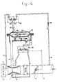
- Figure 4 depicts diagrammatically a regulating device according to the invention which is provided with means for enleaning, at partial load, the gas/air mixture which is delivered to the engine.
- Figure 4 is completely identical to Figure 1, apart from the additional means necessary for the purpose. Only these additional means are indicated and discussed.
- the desired partial-load enleanment is achieved if the natural operation of the pressure regulator 20 is influenced in a manner such that it transmits less gas than it would do inherently. This means that the membrane 23 has to find its equilibrium position in higher position. Since no overpressures at all occur in many cases in the entire regulating system, but always underpressures, while the engine is running, use can be made of one of these underpressures to artificially reduce the pressure in the reference chamber 27.
- the partial-load range is involved in this case, in which the main throttle valve 6 is already closed to a considerable extent and an appreciable underpressure prevails downstream in the engine intake pipe 2, the latter can be used for this purpose. To this end it is fed via a control pipe 91 to a pressure divider 90, which may be of the same type as the pressure divider or pneumatic potentiometer 50 already discussed earlier.
- a pressure divider 90 which may be of the same type as the pressure divider or pneumatic potentiometer 50 already discussed earlier.
- the reference pressure 14 and on the other hand, an underpressure 91 is fed to the potentiometer 90 and a pressure in between is transmitted via the pipe 92 to the reference chamber 27.
- the control pipes 14 and 91 respectively incorporate adjustable throttling devices 93 and 94 respectively.
- control pipe 91 may incorporate a nonreturn valve 95 which is spring loaded in a manner such that it opens and transmits an airflow only above certain air pressures in the engine intake pipe 2 downstream with respect to the main throttle valve 6 and, if the main throttle valve 6 is opened further, closes thanks to the lower underpressure.
- the desired mixture enleanment is achieved only at partial load, while at higher load the enleanment device is inoperative. It may, however, be pointed out that, in the system described, at still higher underpressures downstream of the main throttle valve 6, which occur at still lower engine loads, the device remains operative and continues to bring about the enleanment down to and including no-load. This is undesirable in many cases; for this purpose, the nonreturn valve 95 depicted may be replaced by a valve which only opens and transfers in the desired direction within adjustable underpressure limits so that enleanment of the mixture does in fact take place exclusively in a limited partialload range. It should be pointed out that, with the aid of the device depicted in Figure 5, something comparable is achieved, as will be explained in more detail below.
- Figure 5 is again largely identical to Figure 1 and only the devices which make possible an enrichment possibly required in the partial-load range and which give an additional enrichment on starting have been added.
- the application of an additional underpressure to the underside of the membrane 23, that is, in the control chamber 28, will produce an enrichment of the mixture delivered.
- control pipes 100, 101 which feed a signal from the greater underpressure prevailing there via the pneumatic potentiometer 50 through the control pipe 53 to the control chamber 28.
- a similar simple nonreturn valve 102 or one of the type with lower and upper limitation as discussed in connection with Figure 4 may likewise be situated in the control pipe 100 in order to limit the required mixture enrichment, as required, exclusively to a partial-load range which is determined by the adjustment of the nonreturn valve 102. It is pointed out that the additional underpressure is not fed directly via the control pipes 100 and 101 to the control chamber 28, but the first via combination with the second control pipe 51, to the "divided" beforehand once again in the potentiometer 50. This avoids an excessively coarse effect due to the considerable underpressure downstream of the main throttle valve 6. If necessary, an additional adjustable throttling device 101a may be incorporated in the control pipe 101.
- control pipe 100/101 is tapped upstream with respect to the nonreturn valve by a pipe 103 which is connected to the control pipe 53 which is directly in communication with the control chamber 28.
- the starting pipe 103 is fitted with a shutoff valve 104 which is normally closed. If this is opened while the engine is being started, the very high underpressure which prevails during starting in the engine intake pipe 2 as a consequence of the virtually fully closed main throttle valve 6 will be transmitted via the control line 53 to the control chamber 28 and as a result, temporarily deliver an additional quantity of starting fuel. It is attractive to open the valve 104 at the same time as the starting motor is energized and to close it completely when the starting procedure is terminated.
- valve 104 operated by a solenoid 106 is attractive because it can be energized and de-energized at the same time as the starter motor.
- a valve 104 operated in this manner is therefore associated only with an open and a closed position.
- a throttling device 105 may be incorporated in the starting control pipe 103. It is possible to combine the adjustable throttling device 105 structurally with the open/close valve 104.
- the non-return valve 102 could be constructed in a manner such that it permits a certain passage at partial load and the same or a different one at no-load.
- the general trend in operating gas engines is directed to using lean mixtures, particularly at the higher loads, in order to limit the nitrogen oxide (NOx) emissions in the exhaust gases as much as possible.
- NOx nitrogen oxide
- Figure 6 depicts an embodiment similar to that in Figure 4, but used in the systems, encountered in smaller numbers, in which the gas carburettor is situated downstream with respect to the main throttle valve.
Landscapes
- Engineering & Computer Science (AREA)
- Chemical & Material Sciences (AREA)
- Chemical Kinetics & Catalysis (AREA)
- General Chemical & Material Sciences (AREA)
- Oil, Petroleum & Natural Gas (AREA)
- Combustion & Propulsion (AREA)
- Mechanical Engineering (AREA)
- General Engineering & Computer Science (AREA)
- Output Control And Ontrol Of Special Type Engine (AREA)
- Control Of The Air-Fuel Ratio Of Carburetors (AREA)
- Sampling And Sample Adjustment (AREA)
Priority Applications (1)
| Application Number | Priority Date | Filing Date | Title |
|---|---|---|---|
| AT88202012T ATE101239T1 (de) | 1987-09-22 | 1988-09-14 | Steuervorrichtung fuer gas-venturivergaser. |
Applications Claiming Priority (2)
| Application Number | Priority Date | Filing Date | Title |
|---|---|---|---|
| NL8702256 | 1987-09-22 | ||
| NL8702256A NL8702256A (nl) | 1987-09-22 | 1987-09-22 | Regelinrichting voor venturi-gascarburateur. |
Publications (2)
| Publication Number | Publication Date |
|---|---|
| EP0309044A1 true EP0309044A1 (fr) | 1989-03-29 |
| EP0309044B1 EP0309044B1 (fr) | 1994-02-02 |
Family
ID=19850643
Family Applications (1)
| Application Number | Title | Priority Date | Filing Date |
|---|---|---|---|
| EP88202012A Expired - Lifetime EP0309044B1 (fr) | 1987-09-22 | 1988-09-14 | Dispositif de commande pour carburateur à gaz du type à Venturi |
Country Status (5)
| Country | Link |
|---|---|
| EP (1) | EP0309044B1 (fr) |
| AT (1) | ATE101239T1 (fr) |
| DE (1) | DE3887609T2 (fr) |
| ES (1) | ES2050698T3 (fr) |
| NL (1) | NL8702256A (fr) |
Cited By (6)
| Publication number | Priority date | Publication date | Assignee | Title |
|---|---|---|---|---|
| US6582188B2 (en) | 2000-01-21 | 2003-06-24 | Man B&W Diesel Aktiengesellschaft | Turbocharger |
| EP1596056A1 (fr) * | 2004-05-12 | 2005-11-16 | C.R.F. Società Consortile per Azioni | Système d'admission en gaz pour un moteur à combustion interne comprenant un détendeur connecté au collecteur d'admission |
| US8460413B2 (en) * | 2006-03-09 | 2013-06-11 | Energy & Environmental Research Center Foundation | Method and apparatus for supply of low-Btu gas to an engine generator |
| WO2017121731A1 (fr) * | 2016-01-15 | 2017-07-20 | Mtu Onsite Energy Gmbh | Moteur à combustion interne et procédé pour faire fonctionner un moteur à combustion interne de ce type |
| CN111561406A (zh) * | 2020-06-09 | 2020-08-21 | 重庆大江动力设备制造有限公司 | 一种双缸混合器 |
| EP4137685A1 (fr) * | 2021-08-20 | 2023-02-22 | Caterpillar Inc. | Procédé et système d'alimentation en carburant gazeux |
Families Citing this family (3)
| Publication number | Priority date | Publication date | Assignee | Title |
|---|---|---|---|---|
| CH689565A5 (de) | 1995-03-09 | 1999-06-15 | Bosch Gmbh Robert | Verfahren und Vorrichtung zur Bildung eines turbulenten Kraftstoff-Luft-Gemisches im Verbrennungsraum jedes Zylinders eines ventilgesteuerten Verbrennungsmotors. |
| DE10346983B4 (de) * | 2003-10-09 | 2010-09-09 | Mtu Friedrichshafen Gmbh | Verfahren und eine Vorrichtung zur Regelung eines Kraftstoff-Luft-Gemischs einer mit gasförmigem Kraftstoff betriebenen Brennkraftmaschine |
| US11106227B2 (en) | 2019-05-03 | 2021-08-31 | Zurn Industries, Llc | Pressure reducing valve with an integral venturi |
Citations (5)
| Publication number | Priority date | Publication date | Assignee | Title |
|---|---|---|---|---|
| US2781752A (en) * | 1953-06-16 | 1957-02-19 | Shell Dev | Charge-forming apparatus for gas internal combustion engines |
| US3068085A (en) * | 1958-01-24 | 1962-12-11 | Bosch Arma Corp | Equalizing system for gaseous fuel feeds for internal combustion engines |
| GB1218242A (en) * | 1968-02-17 | 1971-01-06 | Milbank & Keith Garages Ltd | Means for supplying gas to an internal combustion petrol engine as an alternative fuel |
| NL7706500A (en) * | 1977-06-13 | 1978-12-15 | Agas Nederland B V | Gas pressure auxiliary regulator - has throttle with valved by=pass causing excess pressure at very low consumption rate |
| NL8101791A (nl) * | 1981-04-11 | 1982-11-01 | Mannessen Johannes | Verbrandingsmotor voorzien van een verdamper-drukregelaar. |
-
1987
- 1987-09-22 NL NL8702256A patent/NL8702256A/nl not_active Application Discontinuation
-
1988
- 1988-09-14 DE DE3887609T patent/DE3887609T2/de not_active Expired - Fee Related
- 1988-09-14 AT AT88202012T patent/ATE101239T1/de not_active IP Right Cessation
- 1988-09-14 EP EP88202012A patent/EP0309044B1/fr not_active Expired - Lifetime
- 1988-09-14 ES ES88202012T patent/ES2050698T3/es not_active Expired - Lifetime
Patent Citations (5)
| Publication number | Priority date | Publication date | Assignee | Title |
|---|---|---|---|---|
| US2781752A (en) * | 1953-06-16 | 1957-02-19 | Shell Dev | Charge-forming apparatus for gas internal combustion engines |
| US3068085A (en) * | 1958-01-24 | 1962-12-11 | Bosch Arma Corp | Equalizing system for gaseous fuel feeds for internal combustion engines |
| GB1218242A (en) * | 1968-02-17 | 1971-01-06 | Milbank & Keith Garages Ltd | Means for supplying gas to an internal combustion petrol engine as an alternative fuel |
| NL7706500A (en) * | 1977-06-13 | 1978-12-15 | Agas Nederland B V | Gas pressure auxiliary regulator - has throttle with valved by=pass causing excess pressure at very low consumption rate |
| NL8101791A (nl) * | 1981-04-11 | 1982-11-01 | Mannessen Johannes | Verbrandingsmotor voorzien van een verdamper-drukregelaar. |
Non-Patent Citations (1)
| Title |
|---|
| POLYTECHNISCH TIJDSCHRIFT/ELEKTROTECHNIEK ELEKTRONICA, vol. 39, no. 1, January 1983, pages 35-39, Rijswijk, NL; J.D. VAN DER ES et al.: "De toepassing van gasmotoren in warmte/kracht-installaties" * |
Cited By (8)
| Publication number | Priority date | Publication date | Assignee | Title |
|---|---|---|---|---|
| US6582188B2 (en) | 2000-01-21 | 2003-06-24 | Man B&W Diesel Aktiengesellschaft | Turbocharger |
| EP1596056A1 (fr) * | 2004-05-12 | 2005-11-16 | C.R.F. Società Consortile per Azioni | Système d'admission en gaz pour un moteur à combustion interne comprenant un détendeur connecté au collecteur d'admission |
| US7100581B2 (en) | 2004-05-12 | 2006-09-05 | C.R.F. Societa Consortile Per Azioni | Gas feeding system for an internal combustion engine, having a pressure reducing valve connected to the intake manifold |
| US8460413B2 (en) * | 2006-03-09 | 2013-06-11 | Energy & Environmental Research Center Foundation | Method and apparatus for supply of low-Btu gas to an engine generator |
| WO2017121731A1 (fr) * | 2016-01-15 | 2017-07-20 | Mtu Onsite Energy Gmbh | Moteur à combustion interne et procédé pour faire fonctionner un moteur à combustion interne de ce type |
| CN111561406A (zh) * | 2020-06-09 | 2020-08-21 | 重庆大江动力设备制造有限公司 | 一种双缸混合器 |
| EP4137685A1 (fr) * | 2021-08-20 | 2023-02-22 | Caterpillar Inc. | Procédé et système d'alimentation en carburant gazeux |
| US11821389B2 (en) | 2021-08-20 | 2023-11-21 | Caterpillar Inc. | Method and system for supplying fuel gas |
Also Published As
| Publication number | Publication date |
|---|---|
| DE3887609T2 (de) | 1994-05-19 |
| ES2050698T3 (es) | 1994-06-01 |
| NL8702256A (nl) | 1989-04-17 |
| EP0309044B1 (fr) | 1994-02-02 |
| ATE101239T1 (de) | 1994-02-15 |
| DE3887609D1 (de) | 1994-03-17 |
Similar Documents
| Publication | Publication Date | Title |
|---|---|---|
| US3960126A (en) | Pressure regulator of liquefied-gas fuel system for internal combustion engines | |
| US4535728A (en) | Fuel feed control system and control valve for dual fuel operation of an internal combustion engine | |
| US5337722A (en) | Fuel control and feed system for gas fueled engine | |
| US4541397A (en) | Gaseous fuel carburetion system | |
| US4449509A (en) | Gaseous fuel carburetion | |
| US4614168A (en) | Control valve for dual fuel operation of an internal combustion engine | |
| EP0309044B1 (fr) | Dispositif de commande pour carburateur à gaz du type à Venturi | |
| US7191768B2 (en) | Gas fuel feed device | |
| US6340005B1 (en) | Air-fuel control system | |
| US4176641A (en) | Aneroid for a turbocharged engine | |
| US6955160B1 (en) | Gaseous fuel pressure regulator for electronically controlling an outlet pressure | |
| EP0029661A1 (fr) | Système de réglage de combustion pour machine | |
| US3650255A (en) | Method and system for reducing oxides of nitrogen and other pollutants from internal combustion engines | |
| AU721348B2 (en) | Gaseous fuel supply device for an internal combustion engine | |
| US4227496A (en) | Fuel supply devices for internal combustion engines | |
| US4294214A (en) | Engine combustion control system | |
| US5860407A (en) | Gaseous fuel control system for engines | |
| US4886034A (en) | Internal combustion engine control system | |
| US4391252A (en) | Fuel injection system | |
| US4146986A (en) | Device for supplying secondary air for purifying exhaust gases discharged from internal combustion engine | |
| US4161933A (en) | Mixture control apparatus for internal combustion engines | |
| US4125100A (en) | Method and apparatus for controlling the operating mixture supplied to an internal combustion engine | |
| US4326487A (en) | Fuel injection system | |
| US4156415A (en) | Fuel-air mixture control apparatus | |
| US3942496A (en) | Fuel injection system |
Legal Events
| Date | Code | Title | Description |
|---|---|---|---|
| PUAI | Public reference made under article 153(3) epc to a published international application that has entered the european phase |
Free format text: ORIGINAL CODE: 0009012 |
|
| AK | Designated contracting states |
Kind code of ref document: A1 Designated state(s): AT BE CH DE ES FR GB GR IT LI LU NL SE |
|
| 17P | Request for examination filed |
Effective date: 19890925 |
|
| RAP3 | Party data changed (applicant data changed or rights of an application transferred) |
Owner name: NEDERLANDSE ORGANISATIE VOOR TOEGEPAST-NATUURWETEN |
|
| 17Q | First examination report despatched |
Effective date: 19901109 |
|
| GRAA | (expected) grant |
Free format text: ORIGINAL CODE: 0009210 |
|
| AK | Designated contracting states |
Kind code of ref document: B1 Designated state(s): AT BE CH DE ES FR GB GR IT LI LU NL SE |
|
| REF | Corresponds to: |
Ref document number: 101239 Country of ref document: AT Date of ref document: 19940215 Kind code of ref document: T |
|
| ITF | It: translation for a ep patent filed | ||
| REF | Corresponds to: |
Ref document number: 3887609 Country of ref document: DE Date of ref document: 19940317 |
|
| ET | Fr: translation filed | ||
| REG | Reference to a national code |
Ref country code: ES Ref legal event code: FG2A Ref document number: 2050698 Country of ref document: ES Kind code of ref document: T3 |
|
| REG | Reference to a national code |
Ref country code: GR Ref legal event code: FG4A Free format text: 3011595 |
|
| PGFP | Annual fee paid to national office [announced via postgrant information from national office to epo] |
Ref country code: GR Payment date: 19940726 Year of fee payment: 7 |
|
| PGFP | Annual fee paid to national office [announced via postgrant information from national office to epo] |
Ref country code: LU Payment date: 19940901 Year of fee payment: 7 |
|
| PLBE | No opposition filed within time limit |
Free format text: ORIGINAL CODE: 0009261 |
|
| STAA | Information on the status of an ep patent application or granted ep patent |
Free format text: STATUS: NO OPPOSITION FILED WITHIN TIME LIMIT |
|
| 26N | No opposition filed | ||
| EAL | Se: european patent in force in sweden |
Ref document number: 88202012.6 |
|
| PG25 | Lapsed in a contracting state [announced via postgrant information from national office to epo] |
Ref country code: LU Free format text: LAPSE BECAUSE OF NON-PAYMENT OF DUE FEES Effective date: 19950914 |
|
| PGFP | Annual fee paid to national office [announced via postgrant information from national office to epo] |
Ref country code: SE Payment date: 19950918 Year of fee payment: 8 Ref country code: AT Payment date: 19950918 Year of fee payment: 8 |
|
| PGFP | Annual fee paid to national office [announced via postgrant information from national office to epo] |
Ref country code: BE Payment date: 19950919 Year of fee payment: 8 |
|
| PGFP | Annual fee paid to national office [announced via postgrant information from national office to epo] |
Ref country code: CH Payment date: 19951117 Year of fee payment: 8 |
|
| PG25 | Lapsed in a contracting state [announced via postgrant information from national office to epo] |
Ref country code: GR Free format text: THE PATENT HAS BEEN ANNULLED BY A DECISION OF A NATIONAL AUTHORITY Effective date: 19960331 |
|
| REG | Reference to a national code |
Ref country code: GR Ref legal event code: MM2A Free format text: 3011595 |
|
| PG25 | Lapsed in a contracting state [announced via postgrant information from national office to epo] |
Ref country code: AT Effective date: 19960914 |
|
| PG25 | Lapsed in a contracting state [announced via postgrant information from national office to epo] |
Ref country code: SE Effective date: 19960915 |
|
| PG25 | Lapsed in a contracting state [announced via postgrant information from national office to epo] |
Ref country code: LI Effective date: 19960930 Ref country code: CH Effective date: 19960930 Ref country code: BE Effective date: 19960930 |
|
| BERE | Be: lapsed |
Owner name: NEDERLANDSE ORGANISATIE VOOR TOEGEPAST-NATUURWETEN Effective date: 19960930 |
|
| REG | Reference to a national code |
Ref country code: CH Ref legal event code: PL |
|
| EUG | Se: european patent has lapsed |
Ref document number: 88202012.6 |
|
| PGFP | Annual fee paid to national office [announced via postgrant information from national office to epo] |
Ref country code: ES Payment date: 19980331 Year of fee payment: 10 |
|
| PGFP | Annual fee paid to national office [announced via postgrant information from national office to epo] |
Ref country code: GB Payment date: 19980818 Year of fee payment: 11 |
|
| PG25 | Lapsed in a contracting state [announced via postgrant information from national office to epo] |
Ref country code: ES Free format text: LAPSE BECAUSE OF NON-PAYMENT OF DUE FEES Effective date: 19980915 |
|
| PGFP | Annual fee paid to national office [announced via postgrant information from national office to epo] |
Ref country code: FR Payment date: 19980916 Year of fee payment: 11 |
|
| PGFP | Annual fee paid to national office [announced via postgrant information from national office to epo] |
Ref country code: NL Payment date: 19980930 Year of fee payment: 11 |
|
| PGFP | Annual fee paid to national office [announced via postgrant information from national office to epo] |
Ref country code: DE Payment date: 19981030 Year of fee payment: 11 |
|
| PG25 | Lapsed in a contracting state [announced via postgrant information from national office to epo] |
Ref country code: GB Free format text: LAPSE BECAUSE OF NON-PAYMENT OF DUE FEES Effective date: 19990914 |
|
| PG25 | Lapsed in a contracting state [announced via postgrant information from national office to epo] |
Ref country code: NL Free format text: LAPSE BECAUSE OF NON-PAYMENT OF DUE FEES Effective date: 20000401 |
|
| GBPC | Gb: european patent ceased through non-payment of renewal fee |
Effective date: 19990914 |
|
| PG25 | Lapsed in a contracting state [announced via postgrant information from national office to epo] |
Ref country code: FR Free format text: LAPSE BECAUSE OF NON-PAYMENT OF DUE FEES Effective date: 20000531 |
|
| NLV4 | Nl: lapsed or anulled due to non-payment of the annual fee |
Effective date: 20000401 |
|
| PG25 | Lapsed in a contracting state [announced via postgrant information from national office to epo] |
Ref country code: DE Free format text: LAPSE BECAUSE OF NON-PAYMENT OF DUE FEES Effective date: 20000701 |
|
| REG | Reference to a national code |
Ref country code: FR Ref legal event code: ST |
|
| REG | Reference to a national code |
Ref country code: ES Ref legal event code: FD2A Effective date: 19991013 |
|
| PG25 | Lapsed in a contracting state [announced via postgrant information from national office to epo] |
Ref country code: IT Free format text: LAPSE BECAUSE OF NON-PAYMENT OF DUE FEES;WARNING: LAPSES OF ITALIAN PATENTS WITH EFFECTIVE DATE BEFORE 2007 MAY HAVE OCCURRED AT ANY TIME BEFORE 2007. THE CORRECT EFFECTIVE DATE MAY BE DIFFERENT FROM THE ONE RECORDED. Effective date: 20050914 |