EP0309064A1 - Fahrbare Erdbewegungsmaschine mit einem Planierschild - Google Patents
Fahrbare Erdbewegungsmaschine mit einem Planierschild Download PDFInfo
- Publication number
- EP0309064A1 EP0309064A1 EP88202069A EP88202069A EP0309064A1 EP 0309064 A1 EP0309064 A1 EP 0309064A1 EP 88202069 A EP88202069 A EP 88202069A EP 88202069 A EP88202069 A EP 88202069A EP 0309064 A1 EP0309064 A1 EP 0309064A1
- Authority
- EP
- European Patent Office
- Prior art keywords
- scraper blade
- rotor
- frame
- axle
- bowl
- Prior art date
- Legal status (The legal status is an assumption and is not a legal conclusion. Google has not performed a legal analysis and makes no representation as to the accuracy of the status listed.)
- Granted
Links
- 239000002689 soil Substances 0.000 claims abstract description 30
- 230000003247 decreasing effect Effects 0.000 claims description 2
- 238000010008 shearing Methods 0.000 claims description 2
- 230000007423 decrease Effects 0.000 abstract 1
- 230000008878 coupling Effects 0.000 description 3
- 238000010168 coupling process Methods 0.000 description 3
- 238000005859 coupling reaction Methods 0.000 description 3
- 238000009825 accumulation Methods 0.000 description 2
- 230000001070 adhesive effect Effects 0.000 description 2
- 238000012986 modification Methods 0.000 description 2
- 230000004048 modification Effects 0.000 description 2
- 239000000853 adhesive Substances 0.000 description 1
- 230000005540 biological transmission Effects 0.000 description 1
- 230000015572 biosynthetic process Effects 0.000 description 1
- 238000010276 construction Methods 0.000 description 1
- 230000000694 effects Effects 0.000 description 1
- 230000002349 favourable effect Effects 0.000 description 1
- 239000008187 granular material Substances 0.000 description 1
- 238000003780 insertion Methods 0.000 description 1
- 230000037431 insertion Effects 0.000 description 1
- 239000000463 material Substances 0.000 description 1
- 239000004576 sand Substances 0.000 description 1
- 238000007790 scraping Methods 0.000 description 1
- 239000002023 wood Substances 0.000 description 1
Images




Classifications
-
- E—FIXED CONSTRUCTIONS
- E02—HYDRAULIC ENGINEERING; FOUNDATIONS; SOIL SHIFTING
- E02F—DREDGING; SOIL-SHIFTING
- E02F3/00—Dredgers; Soil-shifting machines
- E02F3/04—Dredgers; Soil-shifting machines mechanically-driven
- E02F3/64—Buckets cars, i.e. having scraper bowls
- E02F3/65—Component parts, e.g. drives, control devices
-
- E—FIXED CONSTRUCTIONS
- E02—HYDRAULIC ENGINEERING; FOUNDATIONS; SOIL SHIFTING
- E02F—DREDGING; SOIL-SHIFTING
- E02F3/00—Dredgers; Soil-shifting machines
- E02F3/04—Dredgers; Soil-shifting machines mechanically-driven
- E02F3/64—Buckets cars, i.e. having scraper bowls
- E02F3/6454—Towed (i.e. pulled or pushed) scrapers
- E02F3/6472—Towed (i.e. pulled or pushed) scrapers with elements of the scraper bowls being pivotable for dumping the soil
-
- E—FIXED CONSTRUCTIONS
- E02—HYDRAULIC ENGINEERING; FOUNDATIONS; SOIL SHIFTING
- E02F—DREDGING; SOIL-SHIFTING
- E02F3/00—Dredgers; Soil-shifting machines
- E02F3/04—Dredgers; Soil-shifting machines mechanically-driven
- E02F3/64—Buckets cars, i.e. having scraper bowls
- E02F3/65—Component parts, e.g. drives, control devices
- E02F3/654—Scraper bowls and components mounted on them
- E02F3/655—Loading or elevator mechanisms
-
- E—FIXED CONSTRUCTIONS
- E02—HYDRAULIC ENGINEERING; FOUNDATIONS; SOIL SHIFTING
- E02F—DREDGING; SOIL-SHIFTING
- E02F3/00—Dredgers; Soil-shifting machines
- E02F3/04—Dredgers; Soil-shifting machines mechanically-driven
- E02F3/76—Graders, bulldozers, or the like with scraper plates or ploughshare-like elements; Levelling scarifying devices
- E02F3/7663—Graders with the scraper blade mounted under a frame supported by wheels, or the like
- E02F3/7672—Graders with the scraper blade mounted under a frame supported by wheels, or the like with the scraper blade being pivotable about a horizontal axis disposed parallel to the blade
-
- E—FIXED CONSTRUCTIONS
- E02—HYDRAULIC ENGINEERING; FOUNDATIONS; SOIL SHIFTING
- E02F—DREDGING; SOIL-SHIFTING
- E02F9/00—Component parts of dredgers or soil-shifting machines, not restricted to one of the kinds covered by groups E02F3/00 - E02F7/00
- E02F9/08—Superstructures; Supports for superstructures
- E02F9/0808—Improving mounting or assembling, e.g. frame elements, disposition of all the components on the superstructures
Definitions
- This invention relates to an earth mover comprising at least one wheeled axle; a supported frame movable by the axle, said fraime further including means for pushing up earth, comprising an elongate scraper blade having an earth-facing sharp longitudinal edge substantially right-angled to the forward direction of travel.
- a known earth mover of this type is the so-called scraper.
- Characteristic for earth movers of this type is that the means for pushing up earth, such as the scraper blade, become operative when the apparatus is moved.
- the scraper blade scrapes off a layer of soil in a layer thickness that depends upon the depth of insertion of the scraper blade.
- the layer is then pushed up against the scraper blade and deposited in a bowl located behind the scraper blade, as viewed in the forward direction of travel of the apparatus, said scraper blade being pivotally connected to the bowl.
- the bowl When the bowl is sufficiently filled, it can be closed and subsequently moved to a selected place, where the earth can be discharged from the bowl.
- a problem in the known above described earth movers is that the soil accumulates directly behind the scraper blade in the bowl, so that an efficient loading of the bowl is prevented, and the effective loading capacity is small.
- an earth mover of the above described type is characterized by a cylindrical rotor disposed at an interspace from and, in operative position, above the scraper blade, substantially parallel thereto; means for rotating the rotor in a direction from the longitudinal edge to the upper part of the scraper blade; and bars mounted on the rotor, with the distance from the turning circle circumference of the bars to the scraper blade decreasing in rotation direction.
- An earth mover according to the present invention is not only usable for earth, but more in general for granular materials having the structure of earth.
- the earth mover is also usable for sand, which material is used and processed on a large scale e.g. in road construction.
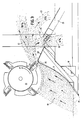
- Fig. 1 shows at 1 an earth mover having a frame including a supporting beam 2, serving at the same time as a drawbar, by means of which the earth mover can be attached through coupling means, not shown, to the rear of a tractor, not shown, and whose forward direction of travel is indicated by arrow S.
- the mobile earth mover shown in the drawing is of the single-axle type and rests with wheels on the ground.
- Fig. 1 shows at 35 a bowl for temporary storage of earth, divided in this example into a front bowl portion 6 and a rear bowl portion 7 communicating with one another. Front portion 6 and rear portion 7 are separated by a threshold zone 9.
- Fig. 1 further shows a rotor 10 and a scraper blade 11 with scraper edge 29, said blade 11 being pivotally connected to the underside of the frame in blade pivot point 12.
- Rotor 10 in this example, is a cylinder arranged horizontally above, and slightly in front of, the scraper blade, with bars 13 being provided on the curved side wall of said cylinder via holding devices 14. The bars extend parallel to the rotor axis.
- a drive shaft 16 For driving and operating the earth mover, use is made of the power take-off shaft and the hydraulic device of a tractor, not shown.
- a cardan shaft through which, in operation, a drive shaft 16 is driven.
- Drive shaft 16 drives the rotor 10 via a gear-chain transmission, comprising gears 17,18, connected to the drive shaft 16, and to the rotor 10, respectively, at their ends, and chains 39.
- the rotation direction of the rotor is indicated by arrow P (Figs. 2 and 3).
- the axle of wheels 5 is pivotally connected at 19 through an arm 20 to the frame. Furthermore, the frame is supported on the wheel axle via at least one hydraulic cylinder 21.
- the front bowl portion 6 has a dividable bottom having in this example rear bottom wall 22 and a bottom flap 23 slidable therefrom, constituting at the same time the front bottom wall.
- Bottom flap 23 in this example is connected on the one hand in pivot point 24 pivotally to the scraper blade 11, and on the other hand through sliding members 25 slidingly to a lower frame portion.
- the position of scraper blade 11 and the pivotally interconnected front bottom wall or bottom flap 23 is determined by at least one hydraulic cylinder 26 (Fig. 1, Fig. 3).
- the rear bowl portion 7 is closed by a closure flap 27, which can be maintained in opened and closed position in response to the operation of at least one hydraulic cylinder 28.
- the soil 40 abutting on scraper blade 11 moves upwards towards the ever narrowing slotted space 31 between the scraper blade and the rotor 10 provided above and in front of the scraper blade, said soil being subjected to an ever increasing pressure force.
- the compacted soil is engaged by the bars and, while being compacted further, is urged further into the slotted space 31 as far as the rib 30 of the scraper blade and beyond.
- the soil contained in the slotted space 31 can attain a speed of about 60 km/h. in the region between rotor 10 and rib 30 of scraper blade 11.
- Such an oriented jet as indicated e.g. at 41, is necessary for effectively filling a bowl of some extent.
- an oriented jet can only be obtained if the soil does not or only slightly stick to the bars and to the scraper blade. It has been experimentally found that such an adhesive effect is absent in an apparatus according to the present invention, not even if soil is processed that is rather strongly adhesive in itself.
- the layer lying against the scraper blade is slowed down against the scraper blade due to friction and falls into the front of the bowl, as shown at 43.
- a tiny portion of the soil passes the rib 30 of the scraper blade at very low speed. This soil can escape directly behind the rib 30 of the scraper blade through a leakage slot 32, thereby preventing an undesirable accumulation of soil directly behind the scraper blade. Such an accumulation would exclude or at least impede partly an oriented jet 41.
- the earth mover When the bowl 35 is filled, the earth mover can be brought into the transport position by energizing the hydraulic cylinder 21, with the entire frame and the interconnected scraper blade 11 being lifted.
- the soil is unloaded, from the rear bowl portion 7 by opening the closure flap 27 with one or more hydraulic cylinders 28 and from the front bowl portion 6 by sliding away the bottom flap 23.
- the piston rod of the hydraulic cylinder(s) 26 is driven outward, while the scraper blade 11 pivots about blade pivot point 12 with its upper portion forward and to a more perpendicular position, thereby entraining the bottom flap 23 connected to the upper portion of the scraper blade.
- the resulting position of the apparatus is shown in Fig. 4. In this position of the scraper blade 11, if desired, after further adjustment of the distance to the ground by means of hydraulic cylinders 26 and 21, the deposited earth can be levelled to a uniform layer by means of scraper blade 11, which is then usable as levelling instrument.
- bottom flap 23 to the upper edge of the scraper blade, as shown in the drawing (Fig. 4), together with the sliding connection 25 of the bottom flap to the frame, ensures that when the bottom of the bowl is opened by energization of the hydraulic cylinder 26, the bottom flap 23 is tilted, in the drawing to the right and upwards. As a result, it is ensured that bowl 35, and its front compartment 6, respectively, is entirely emptied.
- Both members may be attached to the frame independently of one another and be provided with separate operating cylinders.
- the bottom flap could be placed alternatively opposite the scraper blade, instead of directly beyond the scraper blade.
- bowl 35 is divided into two separate compartments 6,7, having separate unloading flaps 25 and 27, respectively.
- the one compartment 6 lies in front of axle 37 and the other compartment 7 lies behind the wheel axle.
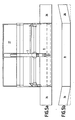
- the working width of the apparatus can be increased by using an additional scraper blade portion at one or both ends of the scraper blade 11.
- Such scraper blade portions shown in Fig. 5 at 36, are oriented preferably slightly obliquely forward, as shown in Fig. 5b.
- FIG. 6 shows diagrammatically the wheel axle 37 of an apparatus according to the present invention.
- Axle 37 has a central portion 50 whereon a support 51 is mounted. Furthermore, a counter-support 52 connected to the arm 20 is mounted about the central portion 50.
- Counter-support 52 and support 51 in this example, have opposite support portions 53,54 projecting above the central portion 50 of axle 37, between which support portions there is mounted a double-acting hydraulic cylinder 55.
- cylinder 55 On energization of cylinder 55, the support portions 53,54 are moved towards or away from one another, resulting in an inclination of the bowl and the scraper blade in the one or the other direction.
- an earth mover according to the present invention may be provided with its own drive means. In that case, at least one wheel pair is present.
- an apparatus according to the present invention without its own drive means may have a multi-axle design.
- a guard plate extending obliquely downwards towards the scraper blade.
- the bars in the example shown, are mounted fixedly but may also be spring-mounted, so that the bars can swing away in the case of too high a load, e.g. because stones or pieces of wood are present between the rotor and the scraper blade. Possibly, also shearing pins or the like may be used. These and similar modifications are deemed to fall within the scope of the present invention.
Landscapes
- Engineering & Computer Science (AREA)
- Mining & Mineral Resources (AREA)
- Civil Engineering (AREA)
- General Engineering & Computer Science (AREA)
- Structural Engineering (AREA)
- Mechanical Engineering (AREA)
- Soil Working Implements (AREA)
Applications Claiming Priority (2)
| Application Number | Priority Date | Filing Date | Title |
|---|---|---|---|
| NL8702301 | 1987-09-25 | ||
| NL8702301A NL8702301A (nl) | 1987-09-25 | 1987-09-25 | Verrijdbare grondverzetinrichting, voorzien van een schraapbord. |
Publications (2)
| Publication Number | Publication Date |
|---|---|
| EP0309064A1 true EP0309064A1 (de) | 1989-03-29 |
| EP0309064B1 EP0309064B1 (de) | 1992-04-08 |
Family
ID=19850668
Family Applications (1)
| Application Number | Title | Priority Date | Filing Date |
|---|---|---|---|
| EP88202069A Expired EP0309064B1 (de) | 1987-09-25 | 1988-09-23 | Fahrbare Erdbewegungsmaschine mit einem Planierschild |
Country Status (7)
| Country | Link |
|---|---|
| US (1) | US4928409A (de) |
| EP (1) | EP0309064B1 (de) |
| JP (1) | JP2691917B2 (de) |
| CA (1) | CA1302957C (de) |
| DE (1) | DE3869889D1 (de) |
| NL (1) | NL8702301A (de) |
| RU (1) | RU1838511C (de) |
Cited By (1)
| Publication number | Priority date | Publication date | Assignee | Title |
|---|---|---|---|---|
| CN107985161A (zh) * | 2017-11-28 | 2018-05-04 | 李亚娟 | 可主动清除积料的渣土车 |
Families Citing this family (2)
| Publication number | Priority date | Publication date | Assignee | Title |
|---|---|---|---|---|
| US20080310916A1 (en) * | 2007-06-15 | 2008-12-18 | Excavation Renaud Belanger Inc. | Longitudinal heap handling system and method |
| WO2016123211A1 (en) | 2015-01-27 | 2016-08-04 | Mtd Products Inc | Snow thrower impeller |
Citations (7)
| Publication number | Priority date | Publication date | Assignee | Title |
|---|---|---|---|---|
| GB616649A (en) * | 1945-12-20 | 1949-01-25 | Ruston Bucyrus Ltd | Improvements in or relating to earth moving scrapers |
| US2564563A (en) * | 1947-08-01 | 1951-08-14 | Marion A Clark | Rotary carry-type scraper |
| US2944350A (en) * | 1955-12-16 | 1960-07-12 | Bartsch Cornelius | Rotary loading and scraping machine |
| GB1144699A (en) * | 1966-09-12 | 1969-03-05 | Clark Equipment Co | Wheeled scrapers for earth-moving |
| US3533174A (en) * | 1968-01-10 | 1970-10-13 | Walter Carston | Earth-moving machine with load-distributing auger |
| US3574960A (en) * | 1968-11-08 | 1971-04-13 | Caterpillar Tractor Co | Backhoe-type self-loading scraper |
| GB1363475A (en) * | 1971-08-25 | 1974-08-14 | Mrs Manufacturing Co | Vehicles for and methods of transporting and dumping earth or other materials |
Family Cites Families (12)
| Publication number | Priority date | Publication date | Assignee | Title |
|---|---|---|---|---|
| US2224869A (en) * | 1938-03-05 | 1940-12-17 | Christian B Jensen | Snowplow |
| US2284412A (en) * | 1938-03-25 | 1942-05-26 | Heil Co | Scraper |
| US2634962A (en) * | 1950-11-10 | 1953-04-14 | Eglitis Victors | Mobile digging and pickup device for loosening and conveying material |
| US3090139A (en) * | 1961-10-05 | 1963-05-21 | James E Hancock | Two-wheeled scraper |
| US3315381A (en) * | 1963-09-06 | 1967-04-25 | Earl H Fisher | Rotary broom for material handling |
| US3474547A (en) * | 1967-02-23 | 1969-10-28 | Caterpillar Tractor Co | Baffle apparatus for self-loading scrapers |
| US3479755A (en) * | 1967-06-13 | 1969-11-25 | Harold D Schropp | Detachable windrow sizer box for material moving scraper |
| US3484843A (en) * | 1967-11-28 | 1969-12-16 | William E Martin | Laterally tiltable self-loading motor scraper |
| US3486251A (en) * | 1968-04-29 | 1969-12-30 | Walter Carston | Earth moving machine incorporating power off-loading system |
| US3706143A (en) * | 1970-07-16 | 1972-12-19 | Caterpillar Tractor Co | Self-loading mechanism for a scraper |
| CA964617A (en) * | 1971-08-13 | 1975-03-18 | Thomas H. Scott | Earth moving vehicle with movable rear wall |
| SU996648A1 (ru) * | 1980-07-23 | 1983-02-15 | Сибирский Ордена Трудового Красного Знамени Автомобильно-Дорожный Институт Им.В.В.Куйбышева | Ковш скрепера |
-
1987
- 1987-09-25 NL NL8702301A patent/NL8702301A/nl not_active Application Discontinuation
-
1988
- 1988-09-23 EP EP88202069A patent/EP0309064B1/de not_active Expired
- 1988-09-23 RU SU884356683A patent/RU1838511C/ru active
- 1988-09-23 US US07/248,984 patent/US4928409A/en not_active Expired - Fee Related
- 1988-09-23 DE DE8888202069T patent/DE3869889D1/de not_active Expired - Lifetime
- 1988-09-26 JP JP63240624A patent/JP2691917B2/ja not_active Expired - Lifetime
- 1988-09-26 CA CA000578417A patent/CA1302957C/en not_active Expired - Lifetime
Patent Citations (7)
| Publication number | Priority date | Publication date | Assignee | Title |
|---|---|---|---|---|
| GB616649A (en) * | 1945-12-20 | 1949-01-25 | Ruston Bucyrus Ltd | Improvements in or relating to earth moving scrapers |
| US2564563A (en) * | 1947-08-01 | 1951-08-14 | Marion A Clark | Rotary carry-type scraper |
| US2944350A (en) * | 1955-12-16 | 1960-07-12 | Bartsch Cornelius | Rotary loading and scraping machine |
| GB1144699A (en) * | 1966-09-12 | 1969-03-05 | Clark Equipment Co | Wheeled scrapers for earth-moving |
| US3533174A (en) * | 1968-01-10 | 1970-10-13 | Walter Carston | Earth-moving machine with load-distributing auger |
| US3574960A (en) * | 1968-11-08 | 1971-04-13 | Caterpillar Tractor Co | Backhoe-type self-loading scraper |
| GB1363475A (en) * | 1971-08-25 | 1974-08-14 | Mrs Manufacturing Co | Vehicles for and methods of transporting and dumping earth or other materials |
Cited By (1)
| Publication number | Priority date | Publication date | Assignee | Title |
|---|---|---|---|---|
| CN107985161A (zh) * | 2017-11-28 | 2018-05-04 | 李亚娟 | 可主动清除积料的渣土车 |
Also Published As
| Publication number | Publication date |
|---|---|
| DE3869889D1 (de) | 1992-05-14 |
| JP2691917B2 (ja) | 1997-12-17 |
| NL8702301A (nl) | 1989-04-17 |
| JPH01111929A (ja) | 1989-04-28 |
| EP0309064B1 (de) | 1992-04-08 |
| CA1302957C (en) | 1992-06-09 |
| RU1838511C (ru) | 1993-08-30 |
| US4928409A (en) | 1990-05-29 |
Similar Documents
| Publication | Publication Date | Title |
|---|---|---|
| US4014390A (en) | Beach cleaner apparatus | |
| US4337586A (en) | Apparatus for the handling and conditioning of snow | |
| US2315007A (en) | Rotary excavator | |
| US3314175A (en) | Earth scraper | |
| CA2234579C (en) | Soil levelling device | |
| US5259699A (en) | Pipeline padding system | |
| US2988832A (en) | Positive ejection mechanism for earth moving apparatus | |
| US20070039212A1 (en) | Scraping device and a system and a method for collecting materials | |
| CA1317318C (en) | Snow removal apparatus | |
| US3343286A (en) | Elevator scraper | |
| US4969279A (en) | Mobile earth mover having a scraper blade | |
| US4506465A (en) | Pivotable towed snow removal blade | |
| US3738028A (en) | Earth moving apparatuses and process | |
| US5074061A (en) | Land arranger | |
| US3596717A (en) | Beach-cleaning vehicle | |
| US3090139A (en) | Two-wheeled scraper | |
| CA1302957C (en) | Mobile earth mover having a scraper blade | |
| US2390421A (en) | Machine for removing snow | |
| US3859741A (en) | Earth moving process | |
| US4976052A (en) | Towed, powered, land grader | |
| US5823707A (en) | Self-propelled remote-controlled stone crusher designed to operate inside trenches | |
| US3958767A (en) | Mobile rock collecting and crushing | |
| US2241252A (en) | Snowplow with power discharge | |
| US5603382A (en) | Shovel attachment with ejector blade for tractors | |
| EP0277733A1 (de) | Fahrzeuge für Guttransport |
Legal Events
| Date | Code | Title | Description |
|---|---|---|---|
| PUAI | Public reference made under article 153(3) epc to a published international application that has entered the european phase |
Free format text: ORIGINAL CODE: 0009012 |
|
| AK | Designated contracting states |
Kind code of ref document: A1 Designated state(s): DE FR GB IT NL |
|
| 17P | Request for examination filed |
Effective date: 19890922 |
|
| 17Q | First examination report despatched |
Effective date: 19910123 |
|
| GRAA | (expected) grant |
Free format text: ORIGINAL CODE: 0009210 |
|
| AK | Designated contracting states |
Kind code of ref document: B1 Designated state(s): DE FR GB IT NL |
|
| REF | Corresponds to: |
Ref document number: 3869889 Country of ref document: DE Date of ref document: 19920514 |
|
| ET | Fr: translation filed | ||
| ITF | It: translation for a ep patent filed | ||
| PLBE | No opposition filed within time limit |
Free format text: ORIGINAL CODE: 0009261 |
|
| STAA | Information on the status of an ep patent application or granted ep patent |
Free format text: STATUS: NO OPPOSITION FILED WITHIN TIME LIMIT |
|
| 26N | No opposition filed | ||
| PGFP | Annual fee paid to national office [announced via postgrant information from national office to epo] |
Ref country code: NL Payment date: 19971031 Year of fee payment: 10 |
|
| PGFP | Annual fee paid to national office [announced via postgrant information from national office to epo] |
Ref country code: FR Payment date: 19980917 Year of fee payment: 11 |
|
| PGFP | Annual fee paid to national office [announced via postgrant information from national office to epo] |
Ref country code: DE Payment date: 19980924 Year of fee payment: 11 |
|
| PGFP | Annual fee paid to national office [announced via postgrant information from national office to epo] |
Ref country code: GB Payment date: 19981001 Year of fee payment: 11 |
|
| PG25 | Lapsed in a contracting state [announced via postgrant information from national office to epo] |
Ref country code: NL Free format text: LAPSE BECAUSE OF NON-PAYMENT OF DUE FEES Effective date: 19990401 |
|
| NLV4 | Nl: lapsed or anulled due to non-payment of the annual fee |
Effective date: 19990401 |
|
| PG25 | Lapsed in a contracting state [announced via postgrant information from national office to epo] |
Ref country code: GB Free format text: LAPSE BECAUSE OF NON-PAYMENT OF DUE FEES Effective date: 19990923 |
|
| GBPC | Gb: european patent ceased through non-payment of renewal fee |
Effective date: 19990923 |
|
| PG25 | Lapsed in a contracting state [announced via postgrant information from national office to epo] |
Ref country code: FR Free format text: LAPSE BECAUSE OF NON-PAYMENT OF DUE FEES Effective date: 20000531 |
|
| PG25 | Lapsed in a contracting state [announced via postgrant information from national office to epo] |
Ref country code: DE Free format text: LAPSE BECAUSE OF NON-PAYMENT OF DUE FEES Effective date: 20000701 |
|
| REG | Reference to a national code |
Ref country code: FR Ref legal event code: ST |
|
| PG25 | Lapsed in a contracting state [announced via postgrant information from national office to epo] |
Ref country code: IT Free format text: LAPSE BECAUSE OF NON-PAYMENT OF DUE FEES;WARNING: LAPSES OF ITALIAN PATENTS WITH EFFECTIVE DATE BEFORE 2007 MAY HAVE OCCURRED AT ANY TIME BEFORE 2007. THE CORRECT EFFECTIVE DATE MAY BE DIFFERENT FROM THE ONE RECORDED. Effective date: 20050923 |