EP0309070A2 - Steuersystem für Fahrzeuggetriebe - Google Patents
Steuersystem für Fahrzeuggetriebe Download PDFInfo
- Publication number
- EP0309070A2 EP0309070A2 EP88302396A EP88302396A EP0309070A2 EP 0309070 A2 EP0309070 A2 EP 0309070A2 EP 88302396 A EP88302396 A EP 88302396A EP 88302396 A EP88302396 A EP 88302396A EP 0309070 A2 EP0309070 A2 EP 0309070A2
- Authority
- EP
- European Patent Office
- Prior art keywords
- clutch
- pressure
- fluid
- valve
- flow
- Prior art date
- Legal status (The legal status is an assumption and is not a legal conclusion. Google has not performed a legal analysis and makes no representation as to the accuracy of the status listed.)
- Withdrawn
Links
- 230000005540 biological transmission Effects 0.000 title claims abstract description 44
- 230000002441 reversible effect Effects 0.000 claims abstract description 51
- 230000035939 shock Effects 0.000 claims abstract description 9
- 239000012530 fluid Substances 0.000 claims description 73
- 238000000034 method Methods 0.000 claims description 7
- 230000007935 neutral effect Effects 0.000 claims description 6
- 238000003825 pressing Methods 0.000 claims description 5
- 230000000712 assembly Effects 0.000 description 7
- 238000000429 assembly Methods 0.000 description 7
- 239000004020 conductor Substances 0.000 description 7
- 230000004048 modification Effects 0.000 description 7
- 238000012986 modification Methods 0.000 description 7
- 230000000694 effects Effects 0.000 description 5
- 230000001105 regulatory effect Effects 0.000 description 4
- 230000001276 controlling effect Effects 0.000 description 3
- 230000036461 convulsion Effects 0.000 description 2
- 238000010586 diagram Methods 0.000 description 2
- 125000006850 spacer group Chemical group 0.000 description 2
- 230000007423 decrease Effects 0.000 description 1
- 230000003111 delayed effect Effects 0.000 description 1
- 238000006073 displacement reaction Methods 0.000 description 1
- 238000004519 manufacturing process Methods 0.000 description 1
- 238000004064 recycling Methods 0.000 description 1
- 230000000717 retained effect Effects 0.000 description 1
- 230000001052 transient effect Effects 0.000 description 1
- 230000007704 transition Effects 0.000 description 1
Images


Classifications
-
- F—MECHANICAL ENGINEERING; LIGHTING; HEATING; WEAPONS; BLASTING
- F16—ENGINEERING ELEMENTS AND UNITS; GENERAL MEASURES FOR PRODUCING AND MAINTAINING EFFECTIVE FUNCTIONING OF MACHINES OR INSTALLATIONS; THERMAL INSULATION IN GENERAL
- F16H—GEARING
- F16H61/00—Control functions within control units of change-speed- or reversing-gearings for conveying rotary motion ; Control of exclusively fluid gearing, friction gearing, gearings with endless flexible members or other particular types of gearing
- F16H61/02—Control functions within control units of change-speed- or reversing-gearings for conveying rotary motion ; Control of exclusively fluid gearing, friction gearing, gearings with endless flexible members or other particular types of gearing characterised by the signals used
- F16H61/0262—Control functions within control units of change-speed- or reversing-gearings for conveying rotary motion ; Control of exclusively fluid gearing, friction gearing, gearings with endless flexible members or other particular types of gearing characterised by the signals used the signals being hydraulic
- F16H61/0265—Control functions within control units of change-speed- or reversing-gearings for conveying rotary motion ; Control of exclusively fluid gearing, friction gearing, gearings with endless flexible members or other particular types of gearing characterised by the signals used the signals being hydraulic for gearshift control, e.g. control functions for performing shifting or generation of shift signals
- F16H61/0272—Control functions within control units of change-speed- or reversing-gearings for conveying rotary motion ; Control of exclusively fluid gearing, friction gearing, gearings with endless flexible members or other particular types of gearing characterised by the signals used the signals being hydraulic for gearshift control, e.g. control functions for performing shifting or generation of shift signals characterised by initiating reverse gearshift
-
- F—MECHANICAL ENGINEERING; LIGHTING; HEATING; WEAPONS; BLASTING
- F16—ENGINEERING ELEMENTS AND UNITS; GENERAL MEASURES FOR PRODUCING AND MAINTAINING EFFECTIVE FUNCTIONING OF MACHINES OR INSTALLATIONS; THERMAL INSULATION IN GENERAL
- F16H—GEARING
- F16H61/00—Control functions within control units of change-speed- or reversing-gearings for conveying rotary motion ; Control of exclusively fluid gearing, friction gearing, gearings with endless flexible members or other particular types of gearing
- F16H61/04—Smoothing ratio shift
- F16H61/06—Smoothing ratio shift by controlling rate of change of fluid pressure
- F16H61/065—Smoothing ratio shift by controlling rate of change of fluid pressure using fluid control means
-
- F—MECHANICAL ENGINEERING; LIGHTING; HEATING; WEAPONS; BLASTING
- F16—ENGINEERING ELEMENTS AND UNITS; GENERAL MEASURES FOR PRODUCING AND MAINTAINING EFFECTIVE FUNCTIONING OF MACHINES OR INSTALLATIONS; THERMAL INSULATION IN GENERAL
- F16H—GEARING
- F16H61/00—Control functions within control units of change-speed- or reversing-gearings for conveying rotary motion ; Control of exclusively fluid gearing, friction gearing, gearings with endless flexible members or other particular types of gearing
- F16H61/12—Detecting malfunction or potential malfunction, e.g. fail safe ; Circumventing or fixing failures
-
- F—MECHANICAL ENGINEERING; LIGHTING; HEATING; WEAPONS; BLASTING
- F16—ENGINEERING ELEMENTS AND UNITS; GENERAL MEASURES FOR PRODUCING AND MAINTAINING EFFECTIVE FUNCTIONING OF MACHINES OR INSTALLATIONS; THERMAL INSULATION IN GENERAL
- F16H—GEARING
- F16H61/00—Control functions within control units of change-speed- or reversing-gearings for conveying rotary motion ; Control of exclusively fluid gearing, friction gearing, gearings with endless flexible members or other particular types of gearing
- F16H61/02—Control functions within control units of change-speed- or reversing-gearings for conveying rotary motion ; Control of exclusively fluid gearing, friction gearing, gearings with endless flexible members or other particular types of gearing characterised by the signals used
- F16H61/0202—Control functions within control units of change-speed- or reversing-gearings for conveying rotary motion ; Control of exclusively fluid gearing, friction gearing, gearings with endless flexible members or other particular types of gearing characterised by the signals used the signals being electric
- F16H61/0251—Elements specially adapted for electric control units, e.g. valves for converting electrical signals to fluid signals
- F16H2061/026—On-off solenoid valve
-
- F—MECHANICAL ENGINEERING; LIGHTING; HEATING; WEAPONS; BLASTING
- F16—ENGINEERING ELEMENTS AND UNITS; GENERAL MEASURES FOR PRODUCING AND MAINTAINING EFFECTIVE FUNCTIONING OF MACHINES OR INSTALLATIONS; THERMAL INSULATION IN GENERAL
- F16H—GEARING
- F16H61/00—Control functions within control units of change-speed- or reversing-gearings for conveying rotary motion ; Control of exclusively fluid gearing, friction gearing, gearings with endless flexible members or other particular types of gearing
- F16H61/12—Detecting malfunction or potential malfunction, e.g. fail safe ; Circumventing or fixing failures
- F16H2061/1232—Bringing the control into a predefined state, e.g. giving priority to particular actuators or gear ratios
-
- F—MECHANICAL ENGINEERING; LIGHTING; HEATING; WEAPONS; BLASTING
- F16—ENGINEERING ELEMENTS AND UNITS; GENERAL MEASURES FOR PRODUCING AND MAINTAINING EFFECTIVE FUNCTIONING OF MACHINES OR INSTALLATIONS; THERMAL INSULATION IN GENERAL
- F16H—GEARING
- F16H61/00—Control functions within control units of change-speed- or reversing-gearings for conveying rotary motion ; Control of exclusively fluid gearing, friction gearing, gearings with endless flexible members or other particular types of gearing
- F16H61/12—Detecting malfunction or potential malfunction, e.g. fail safe ; Circumventing or fixing failures
- F16H2061/1256—Detecting malfunction or potential malfunction, e.g. fail safe ; Circumventing or fixing failures characterised by the parts or units where malfunctioning was assumed or detected
- F16H2061/126—Detecting malfunction or potential malfunction, e.g. fail safe ; Circumventing or fixing failures characterised by the parts or units where malfunctioning was assumed or detected the failing part is the controller
- F16H2061/1268—Electric parts of the controller, e.g. a defect solenoid, wiring or microprocessor
-
- F—MECHANICAL ENGINEERING; LIGHTING; HEATING; WEAPONS; BLASTING
- F16—ENGINEERING ELEMENTS AND UNITS; GENERAL MEASURES FOR PRODUCING AND MAINTAINING EFFECTIVE FUNCTIONING OF MACHINES OR INSTALLATIONS; THERMAL INSULATION IN GENERAL
- F16H—GEARING
- F16H61/00—Control functions within control units of change-speed- or reversing-gearings for conveying rotary motion ; Control of exclusively fluid gearing, friction gearing, gearings with endless flexible members or other particular types of gearing
- F16H61/12—Detecting malfunction or potential malfunction, e.g. fail safe ; Circumventing or fixing failures
- F16H2061/1256—Detecting malfunction or potential malfunction, e.g. fail safe ; Circumventing or fixing failures characterised by the parts or units where malfunctioning was assumed or detected
- F16H2061/1292—Detecting malfunction or potential malfunction, e.g. fail safe ; Circumventing or fixing failures characterised by the parts or units where malfunctioning was assumed or detected the failing part is the power supply, e.g. the electric power supply
-
- F—MECHANICAL ENGINEERING; LIGHTING; HEATING; WEAPONS; BLASTING
- F16—ENGINEERING ELEMENTS AND UNITS; GENERAL MEASURES FOR PRODUCING AND MAINTAINING EFFECTIVE FUNCTIONING OF MACHINES OR INSTALLATIONS; THERMAL INSULATION IN GENERAL
- F16H—GEARING
- F16H2306/00—Shifting
Definitions
- This invention relates generally to an improved hydraulic control system for actuating a vehicle transmission. More particularly, but not by way of limitation, this invention relates to a hydraulic or electro-hydraulic control system for providing rapid smooth shifting of heavy vehicle transmissions.
- this invention provides a hydraulic control system for actuating a transmission that includes a hydraulic clutch wherein the system comprises: valve means for controlling fluid flow to and from the clutch; clutch fill control means for rapidly filling the clutch when the clutch is to be actuated; and pressure control means for lowering the pressure of fluid in the clutch after filling and for gradually increasing the pressure in the clutch until the clutch is fully engaged.
- this invention provides a method of shifting a transmission that includes hydraulic clutches.
- the method comprises the steps of: rapidly filling the clutch with hydraulic fluid; reducing the pressure in the clutch; and applying pressure at a controlled rate to engage the clutch to complete the shift without shock.
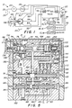
- a control system for a transmission (not shown) that includes forward and reverse clutches 13 and 14 and first and third range clutches 15 and 16 and second and fourth range clutches 17 and 18.
- the pump 22 is also connected with a hydraulic fluid reservoir 24 by a conduit 23.
- a fluid pressure regulator 26 Interposed in the conduit 21 between the pump 22 and the valve means 20 is a fluid pressure regulator 26 that is typically set to supply fluid at about 350 p.s.i.
- the valve means 20 is connected by conduits 28 and 30 with the forward and reverse clutches 13 and 14, by conduits 32 and 34 to first and third range clutches 15 and 16, by conduits 36 and 38 to the second and fourth range clutches 17 and 18.
- the valve means 20 is provided with solenoids 40 and 42 which control the forward and reverse clutches 13 and 14 as will be described in detail hereinafter.
- switches 44 and 46 form part of a forward and reverse electrical control that is designated by the reference character 48.
- the switches 44 and 46 are connected by conductors 50 and 52, respectively, with the solenoids 40 and 42. Drain conduits from the solenoids 40 and 42 are provided with restrictions or orifices 53 and 55, respectively (see Fig. 2).
- the control valve means 20 is also provided with solenoid valves 60 and 62.
- the solenoids 60 and 62 function to control the speed range clutches 15 through 18 as will also be more fully described hereinafter.
- FIG. 2 Shown in FIG. 2 is a cross-sectional view of the control valve means 20 which is made partially schematic for purposes of illustration.
- the control valve means 20 includes a housing 70 which for purposes of manufacturing may be constructed from several parts.
- the fluid pressure conductor 21 is connected to a flow passageway 72 in the housing 70. Fluid from the passageway 72 enters the interior of a flow control member 74 and flows outwardly therefrom through orifices 76 into a fluid supply passageway 82. Flowing through the passageway 82 the fluid passes through an orifice 80 to a connected passageway 78. Fluid flowing through the orifice 80 causes the pressure in the passageway 82 to be greater than the fluid pressure in the passageway 78.
- the passageway 78 is arranged to provide hydraulic fluid to two sets of valves that control the flow of hydraulic fluid to and from the clutches.
- first and second valve members or spools 84 and 86 that are arranged for movement within the housing 70.
- a spring 88 is disposed between the members 84 and 86 and constantly biases them apart and toward the left and right sides of the valve housing 70, respectively.
- the valve members 84 and 86 control the flow of hydraulic fluid to the forward and reverse clutches 13 and 14.
- valve member 84 is subject to hydraulic fluid applied by solenoid 42 thereto through a passageway 85 formed in the valve housing 70.
- valve member 86 is exposed to fluid pressure applied by the solenoid 40 through a passageway 87 also formed in the valve housing 70.
- a second set of valve members is located in the valve housing 70 that are provided to control flow of hydraulic fluid to the speed or range clutches 15 through 18.
- This step of valve members includes a valve member 90 and a valve member 92, each of which is movable within the valve housing 70.
- the valve members 90 and 92 are biased relatively apart and toward the left and right sides of the valve housing 70 by a spring 94.
- the spaces between the valve members 84 and 86 and between the valve members 90 and 92 are connected by a passageway 96 with the reservoir 24.
- valve member 90 is responsive to pressure applied by the solenoid valve 60 through a passageway 91 formed in the valve housing 70.
- the valve member 92 is responsive to pressure applied by the solenoid 62 through a passageway 93, also formed in the housing 70.
- a variable volume signal chamber 100 is located within the housing 70.
- the upper end of the signal chamber 100 is defined by a spacer member 102 that is fixed in the housing 70 and a movable rate control member 104.
- the movable rate control member 104 is arranged in back-to-back relationship to the flow control member 74.
- the members 74 and 104 are held biased relatively apart by springs 106. Pressure in the chamber 100 is always equal to the force of springs 106 divided by cross section area of control member 104.
- a trigger spool 108 that is movable therein.
- the spool 108 is retained in the position illustrated in FIG. 2 by a spring 110.
- the force exerted by the spring 110 must be overcome by the differential in pressure between the hydraulic fluid pressure in the conduits 78 and 82 before the trigger spool 108 will move against the spring 110.
- Full fluid flow to the trigger spool 108 is provided by an auxiliary passageway 112 in conjunction with a check valve 114.
- Orifice 116 is located in the passageway 82 so the fluid flowing from the trigger spool 108 in the reverse direction through the conduit 82 is inhibited.
- the signal chamber 100 is provided with hydraulic fluid from the clutches 15 through 18 through orifice and check valve assemblies 118, 120, 122 and 124.
- the orifice and check valve assembly 124 is connected to the conduit 32 at port 1.
- the check valve and orifice assembly 122 is connected to the conduit 34 at port 2, the check valve and orifice assembly 120 is connected with the conduit 38 at port 4.
- the check valve and orifice assembly 118 is connected with the conductor 36 at port 3. It will be noted that the fluid flowing from the passageway 78 passes through the ports 1, 2, 3 and 4 into the various clutches upon appropriate positioning of the valve members 90 and 92.
- the orifices included in the orifice and check valve assemblies are provided for the purpose of regulating the rate of flow of fluid into the signal chamber 100 from the various clutches.
- the check valves in such assemblies are provided to prevent flow of fluid from the signal chamber 100 toward the clutches which could result in a false signal and restart the automatic cycle of the control system.
- Solenoid valves 40 and 42 are connected at the ends of the valve members 86 and 84, respectively, for the purpose of moving those valve members in the housing 70, as will be described.
- the solenoids 60 and 62 are connected to provide hydraulic fluid under pressure to the ends of the valve members 90 and 92, respectively, for the purpose of moving those valve members.
- a branch passageway 130 is connected to the passageway 78 and leads to a chamber 132 formed in the end of the flow control member 74.
- pressure in the passageway 78 is exerted against the flow control member 74 that urges that valve control member against the force of the springs 106, as well as against a spring 134.
- the passageway 72 is connected through an orifice member 136 in such a manner as to exert pressure therein against a piston or slug 138 that is movable in the housing 70.
- the piston 138 has one end in engagement with the pressure control member 74 in the position shown in FIG. 2. Fluid downstream of the orifice member 136 flows through a passageway 140 to the trigger valve 108.
- valve means 20 which may generally be referred to as the flow control system.
- rate controlmember 104 along with the orifice and check valve assemblies 118, 120, 122 and 124 and the trigger valve 108, comprise a subsystem which may be generally referred to as the pressure control system.
- the valve members or spools 84, 86, 90 and 92 may generally be referred to as valve means for controlling fluid flow to and from the various clutches.
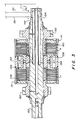
- FIG. 3 illustrates, somewhat in detail, the structure of a pair of typical hydraulically actuated clutches that are used in heavy duty vehicle transmissions.
- the clutches are frequently combined in pairs as illustrated by the forward and reverse clutches 13 and 14.
- the forward clutch 13 is supplied by the conduit 28 through a passageway 142 into a space 144 behind a clutch actuating piston 146.
- the clutch 13 includes various plates 148 that are, upon movement of the piston 144 to the left, brought into frictional engagement causing the gear 150 to rotate with the shaft 152.
- the reverse clutch 14 is supplied by the conduit 30 through passageway 154 into a chamber or space 156 behind the reverse clutch piston 158.
- the reverse clutch 14 is also provided with a plurality of plates 160 which, upon movement of the piston 158, are brought into frictional engagement causing the gear 162 to rotate with the shaft 152.
- the clutches 16 and 18 are not illustrated in detail, but it will be understood that they may be similarly arranged to the clutches 13 and 14.
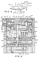
- the direction selector 48 included a hydraulic backup system.
- the hydraulic backup system provides reverse and forward movement for the vehicle in the event that the electrical system operating the valve 48 fails.
- a hydraulic valve 170 (see FIG. 4) is connected into the valve system by a conductor 58 which is connected to the conduit or passageway containing the reverse signal and the conductor 54 which is connected to the passageway containing the forward drive signal.
- Hydraulic fluid is supplied to the valve 170 through the conduit 56 and a return conduit is provided to the reservoir 24.
- an operating lever 172 on the hydraulic valve 170 When the electrical control system is operating properly, an operating lever 172 on the hydraulic valve 170 is in a normal position as illustrated in FIG. 4. Should the electrical circuit fail, the lever 172 is moved to the forward or reverse position as appropriate and when in the forward position, moves the valve into the position wherein the pressure conduit 56 is connected to the forward signal conduit 54 to place the transmission in forward drive while the reverse signal conductor 58 is connected to the reservoir 24. Alternatively, when it is desired to move in a reverse direction, the valve is shifted by the lever 172, moving the valve to a position wherein the forward signal conduit 54 is connected to the reservoir 24 and the pressure conduit 56 is connected to the reverse signal conduit 58 to place the transmission in reverse. Some fluid from conduit 58 will return to reservoir 24 through the disabled solenoid valve 40. However, orifice 53 placed in the drain path of solenoid valve 40 restricts the flow and builds up enough pressure in passage 87 to shift valve member 86.
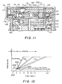
- FIG. 11 is a fragmentary view of a portion of FIG. 5 schematically illustrating a modified form of control valve to accomplish the desired fill rate.
- the modification is performed by adding a passageway 300 that extends from the signal chamber 100 to the bore for the modulator piston 104.
- An orifice 302 is located in the passageway 300 to restrict flow from the signal chamber 100 into the bore of the modulator piston 104.
- the orifice 302 can be varied in size to control the initial rise rate.
- Fluid pressure in the passageway 78 flows past the valve member 84 into a passageway 180 which is dead ended due to the presence of the land 181 on the valve member 86.
- the directional control 48 When it is desired to shift the transmission into reverse, the directional control 48 is shifted into engagement with the switch 44 which energizes the solenoid 40 causing pressurized fluid to flow through the passageway 87 in the housing 70, moving the valve member 86 relatively to the left as illustrated in FIG. 5.
- the land 181 has moved past the port R, thus connecting the passageway 180 through the port R with the conduit 30 leading to the reverse clutch 14. Shifting from reverse to forward requires repositioning the direction control 48 so that the switch 46 is closed, energizing the solenoid 42 and simultaneously deenergizing the solenoid 40 so that the spring 88 drives the valve member 86 to the position illustrated in FIG. 2.
- Energizing the solenoid 42 causes fluid under pressure to flow through the passageway 85, moving the valve member 84 to the right.
- a land 182 located on the valve member 84 connects the passageway 180 to reservoir through passageway 186 and opens a passageway 184 connecting the passageway 78 with the port F to begin energizing the forward clutch 13 through the conductor 28.
- valve member 86 when the valve member 86 is in the leftmost position illustrated in FIG. 5, the port F is connected through an internal passageway 179 in the valve member 86 with the passageway 96 which leads to the reservoir 24.
- the forward clutch 13 is dumped as the reverse clutch 14 is filled.
- movement of the valve member 84 to the right to energize the forward clutch 13 connects an internal passageway 186 therein to the passageway 180 and to the passageway 96 which leads to the reservoir 24 dumping the reverse clutch 14 when the forward clutch 13 is energized.
- First range - FIG. 5 also illustrates the position of the valve members 90 and 92 to supply fluid through the port 1 to the first range clutch. At this point, the system will be in the condition of filling the first range clutch 15.
- fluid under pressure of about 350 p.s.i. flows through into the passageway 72, passing through ports 76 in the control member 74 and then through the orifice 80 into the passageway 78. Due to the high velocity of flow through the orifice 80, a pressure differential, as previously mentioned, is created between the passageway 78 and the passageway 82.
- FIG. 5 The effect of such pressure differential is illustrated in FIG. 5 wherein it can be seen that the trigger valve 108 has shifted to the left under the influence of such pressure differential. Shifting of the trigger valve 108 to the left connects a passageway 190 in the sleeve 102 which is connected the signal chamber 100, to the drain passage 192, dumping the pressure in the signal chamber 100 to the reservoir 24, that is, to approximately atmospheric pressure.
- the piston 138 remains in its leftmost position as illustrated since the pressure in the passageway 140 is connected to the reservoir 24 through a port 192.
- Pressure in chamber 78 which is same as pressure in chamber 132, is always equal to the sum of the spring forces of 134 and 106 divided by the cross-sectional area of the member 74.
- spring 106 is fully relaxed.
- spring 134 determines pressure in chamber 78 and chamber 132 during fill. This is called the fill pressure and typically is about 60 p.s.i. It is more or less constant during fill except for short transient in the beginning and end of clutch fill.
- the pressure in the passageway 78 equalizes with the pressure in the passageway 82.
- the force exerted by the spring 110 on the trigger valve 108 urges it to the right.
- the trigger valve 108 cannot return rapidly to the initial position due to the check valve 114 in the passageway 112 and the orifice 116 in the passageway 82 which restricts the flow of fluid therethrough.
- valve members 90 and 92 are illustrated in FIGS. 2, 5 and 6 in the positions they occupy when the first range speed clutch 15 is engaged. Fluid flows from the passageway 78 through a passageway 204 that is shown in dotted lines connecting the passageway 78 directly to the port 1.
- Second range - When it is desired to shift to second range, the solenoid 62 is energized causing fluid to flow through the passageway 93 moving the valve member 92 to the left as illustrated in FIG. 8. A shoulder 206 on the valve member 92 blocks flow into the port 1 while port 2 is now connected through the passageway 204 to supply the passageway 78. It will also be noted that even though port 1 is blocked, the orifice and check valve assembly 124 remains in fluid communication with the passageway 204 providing fluid flow into the signal chamber 100 therethrough. The orifice and check valve assembly 122 is also connected to the port 2 and thus also supplies fluid into the signal chamber 100.
- Movement of the valve member 92 to the left also opens a passageway 208 in the interior of the valve member 92 to the port 1 and connects that port with the passageway 96 which leads to the reservoir 24.
- the pressure in the first range clutch 15 is being dumped to the reservoir 24.
- the fourth range clutch 18 is exposed to atmospheric through the same passageway 208.
- the third range clutch 16 is connected from the port 3 through a passageway 210 to the passageway 96, thus exposing the port 3 and the third range clutch also to atmospheric.
- all the clutches with the exception of the second range clutch 17 are exposed to atmospheric as the second range clutch 17 is being energized.
- FIG. 9 illustrates the arrangement of the valve members 90 and 92 when the third range clutch 16 is being energized. As shown therein, the valve member 92 remains in the leftmost position. The solenoid 60 is energized directing pressurized fluid through the passageway 91, shifting the valve member 90 to the right. When this occurs, the passageway 204 is connected to atmospheric through a passageway 212 located in the interior of the valve member 90. Connecting the passageways 204 and 212 in this manner dumps the second range clutch 17 to the reservoir 24 or to atmospheric.
- a land 214 on the valve member 90 has shifted to the right, opening the passageway 210 to the fluid in the passageway 78.
- the opposite end of the passageway 210 is connected to port 3 and to the valve and orifice assembly 118.
- the remaining ports 1, 2 and 4 are all connected to the reservoir 24, thus dumping those clutches 15, 17 and 18.
- the orifices located in the orifice and valve assemblies 118, 120, 122 and 124 can be sized appropriately to provide for different flow rates into the signal chamber 100 in accordance with the speed at which it is desired to increase clutch pressure.
- the third range clutch rate of actuation is indicated by the line labeled with the designation "3rd” and "4th".
- the orifice in the orifice and check valve assembly 118 is substantially larger than that in the orifice and valve assembly 124 since it takes only about 0.60 of a second to fully engage the third range clutch 16.
- FIG. 10 illustrates the position of the valve members 90 and 92 during energizing of the fourth range clutch 18. Solenoid 62 has been deenergized permitting the valve member 92 to return to the right end position while the valve member 90 remains in its rightmost position since the solenoid valve 60 remains energized.
- port 1 remains exposed to the reservoir 24 through the passageways 204 and 212.
- Port 2 is dumped to the reservoir 24 through the passageways 208 and 96 and port 3 is exposed directly to the passageway 96.
- the ports 1, 2 and 3 are all exposed to atmospheric.
- each of the speed range clutches for second, third and fourth range are subjected to the rapid fill and a controlled rate of engagement as illustrated by the curve of FIG. 7 and as previously described in connection with the energizing of the first range speed clutch 15. Accordingly, the transmission control system 10 described provides for the rapid filling of the clutches and proper energization thereof without the transmission shock due to the control of the engagement portion of the clutch actuation.
- the transmission control system 10 described utilizes only four solenoids for controlling four shiftable valve members to provide a transmission control having four forward and four reverse speeds in a heavy duty vehicle.
- valve members are arranged to dump all the clutches to reservoir or atmospheric each time that a clutch is energized, and since only two clutches or two solenoids are utilized to control the speed ranges, the system eliminates the difficulties that have been encountered in some of the transmission controls wherein more than one speed range clutch can be engaged at the same time.
- the system includes the emergency hydraulic controls shown in FIG. 4.
- the speed range valve members are biased toward the first range position as illustrated in FIG. 2 by the spring 94, and thus the system automatically goes into a first range speed or drive mode.
- the forward and reverse control system is in neutral when the valve members 84 and 86 are both either deenergized or both energized.
- the transmission control system automatically goes into a neutral direction drive situation. Movement of the lever 172 on the hydraulic emergency system places the vehicle transmission in either forward or reverse so that the vehicle can be moved as desired in either forward or reverse in the first drive speed.
- the effect of the modification is to reduce the shift shock by slowing down the initial pressurization portion.
- the modulator piston 104 moves to the left during pressurization, the passageway 300 is closed by the piston 104 and normal pressure rise rate resumes.
Landscapes
- Engineering & Computer Science (AREA)
- General Engineering & Computer Science (AREA)
- Mechanical Engineering (AREA)
- Physics & Mathematics (AREA)
- Fluid Mechanics (AREA)
- Control Of Transmission Device (AREA)
- Hydraulic Clutches, Magnetic Clutches, Fluid Clutches, And Fluid Joints (AREA)
Applications Claiming Priority (2)
| Application Number | Priority Date | Filing Date | Title |
|---|---|---|---|
| US99348 | 1987-09-21 | ||
| US07/099,348 US4871048A (en) | 1987-09-21 | 1987-09-21 | Control system for vehicle transmissions |
Publications (2)
| Publication Number | Publication Date |
|---|---|
| EP0309070A2 true EP0309070A2 (de) | 1989-03-29 |
| EP0309070A3 EP0309070A3 (de) | 1991-01-02 |
Family
ID=22274572
Family Applications (1)
| Application Number | Title | Priority Date | Filing Date |
|---|---|---|---|
| EP19880302396 Withdrawn EP0309070A3 (de) | 1987-09-21 | 1988-03-18 | Steuersystem für Fahrzeuggetriebe |
Country Status (3)
| Country | Link |
|---|---|
| US (1) | US4871048A (de) |
| EP (1) | EP0309070A3 (de) |
| JP (1) | JPS6483964A (de) |
Cited By (5)
| Publication number | Priority date | Publication date | Assignee | Title |
|---|---|---|---|---|
| FR2694359A1 (fr) * | 1992-07-03 | 1994-02-04 | Kubota Kk | Structure de transmission de propulsion pour un véhicule de travail. |
| WO1995034774A1 (de) * | 1994-06-16 | 1995-12-21 | Zf Friedrichshafen Ag | Schaltventil |
| EP0581124A3 (en) * | 1992-07-31 | 1996-03-06 | Deere & Co | Transmission control system with emergency operating mode |
| DE19612863A1 (de) * | 1996-03-30 | 1997-10-02 | Zahnradfabrik Friedrichshafen | Getriebesteuerung zur Reduzierung der thermischen Belastung von Schaltelementen eines Wendegetriebes |
| WO1997037158A1 (de) * | 1996-03-30 | 1997-10-09 | Zf Friedrichshafen Ag | Hydraulische steuervorrichtung zum schalten eines automatikgetriebes, insbesondere eines cvt-getriebes |
Families Citing this family (10)
| Publication number | Priority date | Publication date | Assignee | Title |
|---|---|---|---|---|
| US5188005A (en) * | 1990-09-14 | 1993-02-23 | Ford Motor Company | Method and system for improving smoothness of shifts in an automatic transmission |
| US5101943A (en) * | 1990-11-30 | 1992-04-07 | Ford New Holland, Inc. | Method of controlling inching clutches |
| US5054599A (en) * | 1990-12-24 | 1991-10-08 | Caterpillar Inc. | End of fill detector for a hydraulic clutch |
| US5343994A (en) * | 1993-03-23 | 1994-09-06 | Caterpillar Inc. | End of fill detector for a hydraulic clutch |
| WO1998029302A1 (en) * | 1996-12-30 | 1998-07-09 | Ab Volvo Penta | Valve assembly and a method of operating a power transmission |
| US6039674A (en) * | 1999-03-26 | 2000-03-21 | Daimlerchrysler Corporation | Quick learn procedure for fill volumes of an electronically controlled automatic transmission |
| US6093133A (en) * | 1999-04-01 | 2000-07-25 | Daimlerchrysler Corporation | Learn 1st 2-3 shift, 1st N-1 learn |
| JP2007331603A (ja) * | 2006-06-15 | 2007-12-27 | Kanzaki Kokyukoki Mfg Co Ltd | 船内外機のシフト装置 |
| US20100300828A1 (en) * | 2009-06-01 | 2010-12-02 | Ford Global Technologies Llc | Dual-Stage Regulator Valve Assembly |
| JP6493430B2 (ja) * | 2017-02-24 | 2019-04-03 | マツダ株式会社 | バルブボディ構造 |
Family Cites Families (11)
| Publication number | Priority date | Publication date | Assignee | Title |
|---|---|---|---|---|
| US3618424A (en) * | 1969-09-02 | 1971-11-09 | Caterpillar Tractor Co | Transmission control system |
| US3809201A (en) * | 1970-10-30 | 1974-05-07 | Kobe Steel Ltd | Modulating valve for vehicle transmission systems |
| DE2136960B2 (de) * | 1971-07-23 | 1978-07-13 | Ardie-Werk Gmbh, 8500 Nuernberg | Vorrichtung zum Schalten von Zahnradwechselgetrieben insbesondere für Kraftfahrzeuge |
| US3991865A (en) * | 1974-02-28 | 1976-11-16 | Kabushiki Kaisha Komatsu Seisakusho | Device for gradually increasing hydraulic pressure |
| JPS554969B2 (de) * | 1974-12-11 | 1980-02-02 | ||
| US3990553A (en) * | 1975-02-10 | 1976-11-09 | Caterpillar Tractor Co. | Transmission control system with improved modulating valve |
| US4046160A (en) * | 1976-02-02 | 1977-09-06 | International Harvester Company | Transmission clutches with sequence valve and piston-controlled pressure modulator |
| US4132302A (en) * | 1976-06-07 | 1979-01-02 | International Harvester Company | Transmission clutches with fully-resetting modulator-load-piston |
| JPS5922100B2 (ja) * | 1977-02-14 | 1984-05-24 | トヨタ自動車株式会社 | 自動変速機の油圧制御装置 |
| US4387731A (en) * | 1979-05-10 | 1983-06-14 | Dresser Industries, Inc. | Modulated transmission with modulator-load-piston loading at linear rate after full reset |
| JPH0830530B2 (ja) * | 1985-07-12 | 1996-03-27 | キャタピラー・インク | 油圧制御システム |
-
1987
- 1987-09-21 US US07/099,348 patent/US4871048A/en not_active Expired - Lifetime
-
1988
- 1988-03-18 EP EP19880302396 patent/EP0309070A3/de not_active Withdrawn
- 1988-04-12 JP JP63090158A patent/JPS6483964A/ja active Pending
Cited By (8)
| Publication number | Priority date | Publication date | Assignee | Title |
|---|---|---|---|---|
| FR2694359A1 (fr) * | 1992-07-03 | 1994-02-04 | Kubota Kk | Structure de transmission de propulsion pour un véhicule de travail. |
| EP0581124A3 (en) * | 1992-07-31 | 1996-03-06 | Deere & Co | Transmission control system with emergency operating mode |
| WO1995034774A1 (de) * | 1994-06-16 | 1995-12-21 | Zf Friedrichshafen Ag | Schaltventil |
| US5797294A (en) * | 1994-06-16 | 1998-08-25 | Zf Friedrichshafen Ag | Shift valve |
| DE19612863A1 (de) * | 1996-03-30 | 1997-10-02 | Zahnradfabrik Friedrichshafen | Getriebesteuerung zur Reduzierung der thermischen Belastung von Schaltelementen eines Wendegetriebes |
| WO1997037158A1 (de) * | 1996-03-30 | 1997-10-09 | Zf Friedrichshafen Ag | Hydraulische steuervorrichtung zum schalten eines automatikgetriebes, insbesondere eines cvt-getriebes |
| US6026699A (en) * | 1996-03-30 | 2000-02-22 | Zf Friedrichshafen Ag | Shuttle shift control using both a directional clutch and a transmission clutch |
| US6030317A (en) * | 1996-03-30 | 2000-02-29 | Zf Friedrichshafen Ag | Hydraulic control for operating an automatic gearbox, especially a continuosly variable transmission |
Also Published As
| Publication number | Publication date |
|---|---|
| JPS6483964A (en) | 1989-03-29 |
| EP0309070A3 (de) | 1991-01-02 |
| US4871048A (en) | 1989-10-03 |
Similar Documents
| Publication | Publication Date | Title |
|---|---|---|
| US4871048A (en) | Control system for vehicle transmissions | |
| DE3532784C2 (de) | ||
| US3468194A (en) | Hydraulic pressure modulating transmission control system | |
| US4827806A (en) | Logic valving for a transmission control | |
| EP0114817B1 (de) | Vom solenoid betriebene kupplung | |
| US3709065A (en) | Compact fluid system for shifting a transmission | |
| US3389770A (en) | Transmission hydraulic control | |
| US4289221A (en) | Hydraulic control system | |
| US3863523A (en) | Hydraulic safety system for a vehicle transmission | |
| KR910000885B1 (ko) | 클러치 우선밸브를 포함하는 변속기 제어회로 | |
| EP0287573B1 (de) | Verteilerventil zum steuern der öffnung eines dämpfenden ablassventils | |
| US4000795A (en) | Apparatus for controlling the pressure of a fluid fed to a clutch | |
| US3181394A (en) | Hydraulic controls | |
| US3570522A (en) | Hydraulic pressure modulating transmission control system | |
| US4093051A (en) | Hydraulic control system for power shift transmission | |
| US3444968A (en) | Fluid controls for automatically neutralizing a vehicle transmission | |
| US4646895A (en) | Hydraulic control for a transmission with high-low powershift and masterclutch | |
| US3465851A (en) | Transmission overshift inhibitor | |
| KR960016792B1 (ko) | 자동 압력 제어용 모듈레이팅 인칭 밸브 | |
| US4111071A (en) | Modulating relief valve with hydraulic safety | |
| US3660975A (en) | Hydrostatic transmission systems | |
| US5496231A (en) | Hydraulic control for a multi-speed power transmission | |
| US4658705A (en) | Control system for hydraulic fluid pressure | |
| US4643285A (en) | Hydraulic control for a master clutch of a transmission | |
| US3667226A (en) | Control for a hydrostatic transmission |
Legal Events
| Date | Code | Title | Description |
|---|---|---|---|
| PUAI | Public reference made under article 153(3) epc to a published international application that has entered the european phase |
Free format text: ORIGINAL CODE: 0009012 |
|
| AK | Designated contracting states |
Kind code of ref document: A2 Designated state(s): BE DE FR GB IT |
|
| PUAL | Search report despatched |
Free format text: ORIGINAL CODE: 0009013 |
|
| AK | Designated contracting states |
Kind code of ref document: A3 Designated state(s): BE DE FR GB IT |
|
| 17P | Request for examination filed |
Effective date: 19910605 |
|
| 17Q | First examination report despatched |
Effective date: 19930311 |
|
| STAA | Information on the status of an ep patent application or granted ep patent |
Free format text: STATUS: THE APPLICATION IS DEEMED TO BE WITHDRAWN |
|
| 18D | Application deemed to be withdrawn |
Effective date: 19930722 |