EP0309074A2 - Elektrische Bremsdruck-Begrenzer- und Steuervorrichtung - Google Patents
Elektrische Bremsdruck-Begrenzer- und Steuervorrichtung Download PDFInfo
- Publication number
- EP0309074A2 EP0309074A2 EP88304677A EP88304677A EP0309074A2 EP 0309074 A2 EP0309074 A2 EP 0309074A2 EP 88304677 A EP88304677 A EP 88304677A EP 88304677 A EP88304677 A EP 88304677A EP 0309074 A2 EP0309074 A2 EP 0309074A2
- Authority
- EP
- European Patent Office
- Prior art keywords
- signal
- brake
- further characterized
- pedal
- difference
- Prior art date
- Legal status (The legal status is an assumption and is not a legal conclusion. Google has not performed a legal analysis and makes no representation as to the accuracy of the status listed.)
- Withdrawn
Links
Images
Classifications
-
- B—PERFORMING OPERATIONS; TRANSPORTING
- B60—VEHICLES IN GENERAL
- B60T—VEHICLE BRAKE CONTROL SYSTEMS OR PARTS THEREOF; BRAKE CONTROL SYSTEMS OR PARTS THEREOF, IN GENERAL; ARRANGEMENT OF BRAKING ELEMENTS ON VEHICLES IN GENERAL; PORTABLE DEVICES FOR PREVENTING UNWANTED MOVEMENT OF VEHICLES; VEHICLE MODIFICATIONS TO FACILITATE COOLING OF BRAKES
- B60T8/00—Arrangements for adjusting wheel-braking force to meet varying vehicular or ground-surface conditions, e.g. limiting or varying distribution of braking force
- B60T8/17—Using electrical or electronic regulation means to control braking
- B60T8/1701—Braking or traction control means specially adapted for particular types of vehicles
- B60T8/1703—Braking or traction control means specially adapted for particular types of vehicles for aircrafts
-
- B—PERFORMING OPERATIONS; TRANSPORTING
- B60—VEHICLES IN GENERAL
- B60T—VEHICLE BRAKE CONTROL SYSTEMS OR PARTS THEREOF; BRAKE CONTROL SYSTEMS OR PARTS THEREOF, IN GENERAL; ARRANGEMENT OF BRAKING ELEMENTS ON VEHICLES IN GENERAL; PORTABLE DEVICES FOR PREVENTING UNWANTED MOVEMENT OF VEHICLES; VEHICLE MODIFICATIONS TO FACILITATE COOLING OF BRAKES
- B60T13/00—Transmitting braking action from initiating means to ultimate brake actuator with power assistance or drive; Brake systems incorporating such transmitting means, e.g. air-pressure brake systems
- B60T13/10—Transmitting braking action from initiating means to ultimate brake actuator with power assistance or drive; Brake systems incorporating such transmitting means, e.g. air-pressure brake systems with fluid assistance, drive, or release
- B60T13/66—Electrical control in fluid-pressure brake systems
- B60T13/662—Electrical control in fluid-pressure brake systems characterised by specified functions of the control system components
-
- B—PERFORMING OPERATIONS; TRANSPORTING
- B60—VEHICLES IN GENERAL
- B60T—VEHICLE BRAKE CONTROL SYSTEMS OR PARTS THEREOF; BRAKE CONTROL SYSTEMS OR PARTS THEREOF, IN GENERAL; ARRANGEMENT OF BRAKING ELEMENTS ON VEHICLES IN GENERAL; PORTABLE DEVICES FOR PREVENTING UNWANTED MOVEMENT OF VEHICLES; VEHICLE MODIFICATIONS TO FACILITATE COOLING OF BRAKES
- B60T8/00—Arrangements for adjusting wheel-braking force to meet varying vehicular or ground-surface conditions, e.g. limiting or varying distribution of braking force
- B60T8/26—Arrangements for adjusting wheel-braking force to meet varying vehicular or ground-surface conditions, e.g. limiting or varying distribution of braking force characterised by producing differential braking between front and rear wheels
- B60T8/266—Arrangements for adjusting wheel-braking force to meet varying vehicular or ground-surface conditions, e.g. limiting or varying distribution of braking force characterised by producing differential braking between front and rear wheels using valves or actuators with external control means
-
- B—PERFORMING OPERATIONS; TRANSPORTING
- B60—VEHICLES IN GENERAL
- B60T—VEHICLE BRAKE CONTROL SYSTEMS OR PARTS THEREOF; BRAKE CONTROL SYSTEMS OR PARTS THEREOF, IN GENERAL; ARRANGEMENT OF BRAKING ELEMENTS ON VEHICLES IN GENERAL; PORTABLE DEVICES FOR PREVENTING UNWANTED MOVEMENT OF VEHICLES; VEHICLE MODIFICATIONS TO FACILITATE COOLING OF BRAKES
- B60T8/00—Arrangements for adjusting wheel-braking force to meet varying vehicular or ground-surface conditions, e.g. limiting or varying distribution of braking force
- B60T8/32—Arrangements for adjusting wheel-braking force to meet varying vehicular or ground-surface conditions, e.g. limiting or varying distribution of braking force responsive to a speed condition, e.g. acceleration or deceleration
- B60T8/321—Arrangements for adjusting wheel-braking force to meet varying vehicular or ground-surface conditions, e.g. limiting or varying distribution of braking force responsive to a speed condition, e.g. acceleration or deceleration deceleration
- B60T8/325—Systems specially adapted for aircraft
-
- B—PERFORMING OPERATIONS; TRANSPORTING
- B64—AIRCRAFT; AVIATION; COSMONAUTICS
- B64C—AEROPLANES; HELICOPTERS
- B64C25/00—Alighting gear
- B64C25/32—Alighting gear characterised by elements which contact the ground or similar surface
- B64C25/42—Arrangement or adaptation of brakes
Definitions
- the invention herein resides in the art of braking systems and, more particularly, to electrical braking control systems for vehicles such as aircraft. Specifically, the invention relates to an apparatus for reducing the effect of the initial torque peak typically associated with carbon brakes.
- carbon brake discs are especially adapted for implementation in aircraft braking systems.
- carbon brake systems demonstrate an initial torque peak of high amplitude.
- the first application of the brakes upon landing often results in a deep skid, causing the antiskid system of the aircraft to initialize its modulator at a level characterized by the inordinately high torque characteristic of the carbon brake on initial application.
- the modulator serves to control the average brake pressure during the braking operation and, if initialized as a function of a brake characteristic which terminates after the initial brake application, reduces the efficiency of the overall braking system.
- the high torque characteristic of carbon brakes substantially disappears after the first brake application and, in that regard, is substantially a transient signal.
- Still a further aspect of the invention is to provide an electrical brake pressure limiter and controller which may be readily implemented with state-of-the-art electrical brake systems as utilized in aircraft.
- an electrical brake pressure limiter and controller comprising: a brake pedal; first means connected to said brake pedal for producing a first signal corresponding to a position of depression of said brake pedal; second means connected to said first means, receiving said first signal and generating therefrom a second signal, said second signal being limited as to both initial amplitude and rate of increase in amplitude; a valve driver receiving said second signal and generating a brake control signal therefrom; and a brake valve receiving said brake control signal and controlling application and release of brake pressure to a brake as a function thereof.
- a brake pressure limiter and controller circuit is designated generally by the numeral 10.
- a brake pedal and transducer 12 is provided for pilot actuation in order to achieve braking operation. While various type known transducers including optical transducers may be applied to the invention, for the purposes of this description, the brake pedal is shown interconnected with a linear variable differential transformer (LVDT) which presents an AC output having an amplitude determined by the brake pedal position.
- the AC output of the brake pedal and transducer 12 is passed to an AC to DC converter 14 in which the brake signal is converted to a DC signal having an amplitude corresponding to brake pedal position.
- the converter 14 is part and parcel of an electronic brake control unit 16 which also includes as a portion thereof a microprocessor 18, the control algorithm of which is shown in flow chart form in the drawing.
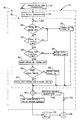
- a sample period T for sampling data from the converter 14 corresponding to brake pedal position is illustratively designated by the numeral 20. Suffice it to say that the microprocessor 18 samples data from the converter 14 at a rate dependent upon the sample period T.
- pedal in is the present signal level from the brake pedal transducer 12 as provided through the converter 14.
- The”initial limit is the pedal signal limit which represents the maximum pressure which can be initially applied.
- the “pedal delta” is that increment added to the “pedal out” signal each sample period which controls the pressure application rate from the "initial limit” to the maximum metered pressure.
- pedal out is the modified pedal signal input to the valve drive summing function to be discussed below.
- the pedal in signal is compared to the pedal out signal at the logic block 22 and, if found to be greater, is also compared against the initial limit which is set at a percentage of the maximum incoming pedal signal, such percentage being dependent upon the brake system characteristics, aircraft parameters, and the like. If the pedal in signal is greater than the initial limit as determined at logic block 24, then the pedal out signal is compared against the initial limit at logic block 26. On the first pass through the algorithm of microprocessor 18, the pedal out signal is "0" and, accordingly, the pedal out signal is set to equal the initial limit at 28. On the next pass through the algorithm, the comparison made at logic block 26 would typically result in an affirmative decision, in which case the function at 30 would be performed.
- the difference between the pedal in and pedal out signals is determined and designated as "ramp".
- this difference is compared against pedal delta and, if the difference is greater than pedal delta, then the pedal out signal is incremented by pedal delta at function block 34. If the ramp signal is not greater than pedal delta, then the pedal out signal is set to equal the pedal in signal as at function block 38. Finally, it will be noted that in the event the pedal in signal is not greater than the pedal out signal, indicating that the pilot has reduced brake pressure, then function block 36 dictates that the pedal out signal be set to equal the pedal in signal.
- the algorithm of the microprocessor 18 is adapted to accomodate all types of braking functions demanded by the pilot including taxiing and increases and decreases in brake pressure or brake torque demand. It should also be appreciated that the initial limit allows for a minimal application of brake pressure initially such that the high transient torque characteristics of the carbon brakes are greatly reduced, as are their effects on the antiskid system. Accordingly, the antiskid system associated with the braking system just described is allowed to initialize at a more effective level than had the braking system experienced a deep skid from its initial brake application.
- the pedal out circuit is passed to the summer 40 where it is combined with the antiskid signal from the antiskid control algorithm 42.
- the output of the summer 40 is applied to a digital-to-analog converter and valve driver circuit 44 which provides appropriate valve current to the brake control valve 46.
- the valve 46 accordingly controls the application and release of brake pressure at the wheel and brake assembly 48.
- the wheel speed of the wheel and brake assembly 48 is monitored over an appropriate sample period T designated by the switch 50.
Landscapes
- Engineering & Computer Science (AREA)
- Mechanical Engineering (AREA)
- Transportation (AREA)
- Aviation & Aerospace Engineering (AREA)
- Regulating Braking Force (AREA)
- Braking Systems And Boosters (AREA)
Applications Claiming Priority (2)
| Application Number | Priority Date | Filing Date | Title |
|---|---|---|---|
| US99189 | 1987-09-21 | ||
| US07/099,189 US5146408A (en) | 1987-09-21 | 1987-09-21 | Electrical brake pressure limiter and controller |
Publications (2)
| Publication Number | Publication Date |
|---|---|
| EP0309074A2 true EP0309074A2 (de) | 1989-03-29 |
| EP0309074A3 EP0309074A3 (en) | 1990-08-22 |
Family
ID=22273419
Family Applications (1)
| Application Number | Title | Priority Date | Filing Date |
|---|---|---|---|
| EP88304677A Withdrawn EP0309074A3 (en) | 1987-09-21 | 1988-05-24 | Electrical brake pressure limiter and controller |
Country Status (2)
| Country | Link |
|---|---|
| US (1) | US5146408A (de) |
| EP (1) | EP0309074A3 (de) |
Cited By (2)
| Publication number | Priority date | Publication date | Assignee | Title |
|---|---|---|---|---|
| WO1990013463A1 (en) * | 1989-05-08 | 1990-11-15 | Group Lotus Plc | A wheeled vehicle control system |
| GB2416009A (en) * | 2004-05-12 | 2006-01-11 | Dunlop Aerospace Ltd | Hydraulic fluid control apparatus |
Families Citing this family (5)
| Publication number | Priority date | Publication date | Assignee | Title |
|---|---|---|---|---|
| JP3202032B2 (ja) * | 1991-06-03 | 2001-08-27 | 本田技研工業株式会社 | 電気自動車用ブレーキ制御装置 |
| DE4430461A1 (de) * | 1994-08-27 | 1996-02-29 | Teves Gmbh Alfred | Verfahren zur Steuerung des Bremsdrucks in Abhängigkeit von der Pedalbetätigungsgeschwindigkeit |
| US9227608B2 (en) * | 2009-08-12 | 2016-01-05 | Meggitt Aircraft Braking Systems | Decentralized electric brake system |
| US9676377B2 (en) * | 2015-06-17 | 2017-06-13 | Ford Global Technologies, Llc | Speed limiting comfort enhancement |
| EP3597496B1 (de) | 2018-07-16 | 2020-09-02 | Safran Landing Systems UK Limited | Flugzeugfahrwerkanordnung |
Family Cites Families (11)
| Publication number | Priority date | Publication date | Assignee | Title |
|---|---|---|---|---|
| FR2242267B1 (de) * | 1973-09-05 | 1976-10-01 | Aerospatiale | |
| US4293165A (en) * | 1978-01-26 | 1981-10-06 | Crane Co. | Electronic control brake and skid control system |
| FR2473464A1 (fr) * | 1980-01-11 | 1981-07-17 | Aerospatiale | Procede et dispositif pour le freinage d'un aeronef par recherche d'un glissement optimal des roues freinees |
| US4484282A (en) * | 1980-05-05 | 1984-11-20 | Crane Co. | Apparatus for generating a lead signal in an antiskid system |
| DE3137207A1 (de) * | 1981-09-18 | 1983-04-07 | Dr.Ing.H.C. F. Porsche Ag, 7000 Stuttgart | "bremssystem, vorzugsweise fuer ein kraftfahrzeug" |
| US4555766A (en) * | 1981-10-09 | 1985-11-26 | General Signal Corporation | Brake control system for vehicles |
| US4610484A (en) * | 1983-09-23 | 1986-09-09 | The Boeing Company | Deceleration control brake system |
| FR2556313B1 (fr) * | 1983-12-09 | 1986-09-19 | Messier Hispano Bugatti Sa | Procede de commande du freinage d'un vehicule sur roues |
| FR2568203B1 (fr) * | 1984-07-25 | 1986-12-05 | Aerospatiale | Systeme pour le freinage d'un vehicule, notamment d'un aeronef roulant sur le sol, et regulateur d'antipatinage pour ce systeme |
| DE3535110C2 (de) * | 1985-10-02 | 1993-11-04 | Teves Gmbh Alfred | Schaltungsanordnung zur regelung des bremsdruckes einer schlupfgeregelten bremsanlage fuer allradangetriebene kraftfahrzeuge |
| JPS62157851A (ja) * | 1985-12-28 | 1987-07-13 | Toyota Motor Corp | 加速スリツプ制御装置 |
-
1987
- 1987-09-21 US US07/099,189 patent/US5146408A/en not_active Expired - Lifetime
-
1988
- 1988-05-24 EP EP88304677A patent/EP0309074A3/en not_active Withdrawn
Cited By (3)
| Publication number | Priority date | Publication date | Assignee | Title |
|---|---|---|---|---|
| WO1990013463A1 (en) * | 1989-05-08 | 1990-11-15 | Group Lotus Plc | A wheeled vehicle control system |
| GB2416009A (en) * | 2004-05-12 | 2006-01-11 | Dunlop Aerospace Ltd | Hydraulic fluid control apparatus |
| US8205830B2 (en) | 2004-05-12 | 2012-06-26 | Meggitt Aerospace Limited | Hydraulic fluid control apparatus |
Also Published As
| Publication number | Publication date |
|---|---|
| EP0309074A3 (en) | 1990-08-22 |
| US5146408A (en) | 1992-09-08 |
Similar Documents
| Publication | Publication Date | Title |
|---|---|---|
| US5378053A (en) | Maximized regenerative braking vehicle braking controller | |
| US6752353B2 (en) | Optimal control design for aircraft antiskid brake control systems | |
| US6076899A (en) | Method and apparatus for controlling the brake system of electric drive vehicles | |
| CA2010642C (en) | Adaptive wheel slip threshold | |
| US4336592A (en) | Antiskid control system for brakes which exhibit large changes in lining friction coefficient | |
| EP0936115A3 (de) | Bremssteuerungssyteme und Verfahren | |
| US20030020326A1 (en) | System and method for adaptive brake application and initial skid detection | |
| US4763263A (en) | Propulsion control using longitudinal acceleration to determine slip thresholds | |
| JP2694051B2 (ja) | ブレーキ制御システム | |
| EP0152300A2 (de) | Bremssteuersystem | |
| US3674320A (en) | Adaptive braking control system | |
| EP0936116A3 (de) | Bremssteuerungssysteme und Verfahren | |
| US5146408A (en) | Electrical brake pressure limiter and controller | |
| EP1110833A3 (de) | Blockierschutz-Bremsregelsystem für Kraftfahrzeuge | |
| US5419623A (en) | System for split-to-high mu detection and control for anti-lock brake systems | |
| JPH01257654A (ja) | 車両のトラクションコントロール装置 | |
| GB1417673A (en) | Anti-lock brake system controls | |
| US4613190A (en) | Modulator preset circuit | |
| US5752747A (en) | Method for equalizing the wear of brake linings of a vehicle | |
| WO1995003956A9 (en) | Method and system for split-to-high mu control for anti-lock brake systems | |
| GB1502505A (en) | Anti-skid system and brake control | |
| RU2108247C1 (ru) | Способ автоматического управления торможением транспортного средства | |
| JPS6050061A (ja) | アンチスキッド制御方法 | |
| US3847447A (en) | Adaptive braking system | |
| US4933608A (en) | Method of electrically braking a linear motor |
Legal Events
| Date | Code | Title | Description |
|---|---|---|---|
| PUAI | Public reference made under article 153(3) epc to a published international application that has entered the european phase |
Free format text: ORIGINAL CODE: 0009012 |
|
| AK | Designated contracting states |
Kind code of ref document: A2 Designated state(s): DE FR GB |
|
| PUAL | Search report despatched |
Free format text: ORIGINAL CODE: 0009013 |
|
| AK | Designated contracting states |
Kind code of ref document: A3 Designated state(s): DE FR GB |
|
| 17P | Request for examination filed |
Effective date: 19901213 |
|
| 17Q | First examination report despatched |
Effective date: 19920127 |
|
| STAA | Information on the status of an ep patent application or granted ep patent |
Free format text: STATUS: THE APPLICATION HAS BEEN WITHDRAWN |
|
| 18W | Application withdrawn |
Withdrawal date: 19920626 |