EP0309189A2 - Récipient et anneau de recouvrement pour son bord serti - Google Patents
Récipient et anneau de recouvrement pour son bord serti Download PDFInfo
- Publication number
- EP0309189A2 EP0309189A2 EP88308685A EP88308685A EP0309189A2 EP 0309189 A2 EP0309189 A2 EP 0309189A2 EP 88308685 A EP88308685 A EP 88308685A EP 88308685 A EP88308685 A EP 88308685A EP 0309189 A2 EP0309189 A2 EP 0309189A2
- Authority
- EP
- European Patent Office
- Prior art keywords
- seam ring
- seam
- container
- container body
- closure
- Prior art date
- Legal status (The legal status is an assumption and is not a legal conclusion. Google has not performed a legal analysis and makes no representation as to the accuracy of the status listed.)
- Withdrawn
Links
Images



Classifications
-
- B—PERFORMING OPERATIONS; TRANSPORTING
- B65—CONVEYING; PACKING; STORING; HANDLING THIN OR FILAMENTARY MATERIAL
- B65D—CONTAINERS FOR STORAGE OR TRANSPORT OF ARTICLES OR MATERIALS, e.g. BAGS, BARRELS, BOTTLES, BOXES, CANS, CARTONS, CRATES, DRUMS, JARS, TANKS, HOPPERS, FORWARDING CONTAINERS; ACCESSORIES, CLOSURES, OR FITTINGS THEREFOR; PACKAGING ELEMENTS; PACKAGES
- B65D81/00—Containers, packaging elements, or packages, for contents presenting particular transport or storage problems, or adapted to be used for non-packaging purposes after removal of contents
- B65D81/34—Containers, packaging elements, or packages, for contents presenting particular transport or storage problems, or adapted to be used for non-packaging purposes after removal of contents for packaging foodstuffs or other articles intended to be cooked or heated within the package
- B65D81/3446—Containers, packaging elements, or packages, for contents presenting particular transport or storage problems, or adapted to be used for non-packaging purposes after removal of contents for packaging foodstuffs or other articles intended to be cooked or heated within the package specially adapted to be heated by microwaves
- B65D81/3453—Rigid containers, e.g. trays, bottles, boxes, cups
-
- B—PERFORMING OPERATIONS; TRANSPORTING
- B65—CONVEYING; PACKING; STORING; HANDLING THIN OR FILAMENTARY MATERIAL
- B65D—CONTAINERS FOR STORAGE OR TRANSPORT OF ARTICLES OR MATERIALS, e.g. BAGS, BARRELS, BOTTLES, BOXES, CANS, CARTONS, CRATES, DRUMS, JARS, TANKS, HOPPERS, FORWARDING CONTAINERS; ACCESSORIES, CLOSURES, OR FITTINGS THEREFOR; PACKAGING ELEMENTS; PACKAGES
- B65D17/00—Rigid or semi-rigid containers specially constructed to be opened by cutting or piercing, or by tearing of frangible members or portions
- B65D17/28—Rigid or semi-rigid containers specially constructed to be opened by cutting or piercing, or by tearing of frangible members or portions at lines or points of weakness
- B65D17/401—Rigid or semi-rigid containers specially constructed to be opened by cutting or piercing, or by tearing of frangible members or portions at lines or points of weakness characterised by having the line of weakness provided in an end wall
- B65D17/4011—Rigid or semi-rigid containers specially constructed to be opened by cutting or piercing, or by tearing of frangible members or portions at lines or points of weakness characterised by having the line of weakness provided in an end wall for opening completely by means of a tearing tab
-
- B—PERFORMING OPERATIONS; TRANSPORTING
- B65—CONVEYING; PACKING; STORING; HANDLING THIN OR FILAMENTARY MATERIAL
- B65D—CONTAINERS FOR STORAGE OR TRANSPORT OF ARTICLES OR MATERIALS, e.g. BAGS, BARRELS, BOTTLES, BOXES, CANS, CARTONS, CRATES, DRUMS, JARS, TANKS, HOPPERS, FORWARDING CONTAINERS; ACCESSORIES, CLOSURES, OR FITTINGS THEREFOR; PACKAGING ELEMENTS; PACKAGES
- B65D51/00—Closures not otherwise provided for
- B65D51/18—Arrangements of closures with protective outer cap-like covers or of two or more co-operating closures
- B65D51/20—Caps, lids, or covers co-operating with an inner closure arranged to be opened by piercing, cutting, or tearing
-
- B—PERFORMING OPERATIONS; TRANSPORTING
- B65—CONVEYING; PACKING; STORING; HANDLING THIN OR FILAMENTARY MATERIAL
- B65D—CONTAINERS FOR STORAGE OR TRANSPORT OF ARTICLES OR MATERIALS, e.g. BAGS, BARRELS, BOTTLES, BOXES, CANS, CARTONS, CRATES, DRUMS, JARS, TANKS, HOPPERS, FORWARDING CONTAINERS; ACCESSORIES, CLOSURES, OR FITTINGS THEREFOR; PACKAGING ELEMENTS; PACKAGES
- B65D2251/00—Details relating to container closures
- B65D2251/0003—Two or more closures
- B65D2251/0006—Upper closure
- B65D2251/0018—Upper closure of the 43-type
-
- B—PERFORMING OPERATIONS; TRANSPORTING
- B65—CONVEYING; PACKING; STORING; HANDLING THIN OR FILAMENTARY MATERIAL
- B65D—CONTAINERS FOR STORAGE OR TRANSPORT OF ARTICLES OR MATERIALS, e.g. BAGS, BARRELS, BOTTLES, BOXES, CANS, CARTONS, CRATES, DRUMS, JARS, TANKS, HOPPERS, FORWARDING CONTAINERS; ACCESSORIES, CLOSURES, OR FITTINGS THEREFOR; PACKAGING ELEMENTS; PACKAGES
- B65D2251/00—Details relating to container closures
- B65D2251/0003—Two or more closures
- B65D2251/0068—Lower closure
- B65D2251/0071—Lower closure of the 17-type
-
- B—PERFORMING OPERATIONS; TRANSPORTING
- B65—CONVEYING; PACKING; STORING; HANDLING THIN OR FILAMENTARY MATERIAL
- B65D—CONTAINERS FOR STORAGE OR TRANSPORT OF ARTICLES OR MATERIALS, e.g. BAGS, BARRELS, BOTTLES, BOXES, CANS, CARTONS, CRATES, DRUMS, JARS, TANKS, HOPPERS, FORWARDING CONTAINERS; ACCESSORIES, CLOSURES, OR FITTINGS THEREFOR; PACKAGING ELEMENTS; PACKAGES
- B65D2543/00—Lids or covers essentially for box-like containers
- B65D2543/00009—Details of lids or covers for rigid or semi-rigid containers
- B65D2543/00018—Overall construction of the lid
- B65D2543/00037—Disc closures
-
- B—PERFORMING OPERATIONS; TRANSPORTING
- B65—CONVEYING; PACKING; STORING; HANDLING THIN OR FILAMENTARY MATERIAL
- B65D—CONTAINERS FOR STORAGE OR TRANSPORT OF ARTICLES OR MATERIALS, e.g. BAGS, BARRELS, BOTTLES, BOXES, CANS, CARTONS, CRATES, DRUMS, JARS, TANKS, HOPPERS, FORWARDING CONTAINERS; ACCESSORIES, CLOSURES, OR FITTINGS THEREFOR; PACKAGING ELEMENTS; PACKAGES
- B65D2543/00—Lids or covers essentially for box-like containers
- B65D2543/00009—Details of lids or covers for rigid or semi-rigid containers
- B65D2543/00018—Overall construction of the lid
- B65D2543/00064—Shape of the outer periphery
- B65D2543/00074—Shape of the outer periphery curved
- B65D2543/00092—Shape of the outer periphery curved circular
-
- B—PERFORMING OPERATIONS; TRANSPORTING
- B65—CONVEYING; PACKING; STORING; HANDLING THIN OR FILAMENTARY MATERIAL
- B65D—CONTAINERS FOR STORAGE OR TRANSPORT OF ARTICLES OR MATERIALS, e.g. BAGS, BARRELS, BOTTLES, BOXES, CANS, CARTONS, CRATES, DRUMS, JARS, TANKS, HOPPERS, FORWARDING CONTAINERS; ACCESSORIES, CLOSURES, OR FITTINGS THEREFOR; PACKAGING ELEMENTS; PACKAGES
- B65D2543/00—Lids or covers essentially for box-like containers
- B65D2543/00009—Details of lids or covers for rigid or semi-rigid containers
- B65D2543/00018—Overall construction of the lid
- B65D2543/00259—Materials used
- B65D2543/00268—Paper
-
- B—PERFORMING OPERATIONS; TRANSPORTING
- B65—CONVEYING; PACKING; STORING; HANDLING THIN OR FILAMENTARY MATERIAL
- B65D—CONTAINERS FOR STORAGE OR TRANSPORT OF ARTICLES OR MATERIALS, e.g. BAGS, BARRELS, BOTTLES, BOXES, CANS, CARTONS, CRATES, DRUMS, JARS, TANKS, HOPPERS, FORWARDING CONTAINERS; ACCESSORIES, CLOSURES, OR FITTINGS THEREFOR; PACKAGING ELEMENTS; PACKAGES
- B65D2543/00—Lids or covers essentially for box-like containers
- B65D2543/00009—Details of lids or covers for rigid or semi-rigid containers
- B65D2543/00435—Lids secured to an intermediate ring or like annular member fixed to the container mouth
-
- B—PERFORMING OPERATIONS; TRANSPORTING
- B65—CONVEYING; PACKING; STORING; HANDLING THIN OR FILAMENTARY MATERIAL
- B65D—CONTAINERS FOR STORAGE OR TRANSPORT OF ARTICLES OR MATERIALS, e.g. BAGS, BARRELS, BOTTLES, BOXES, CANS, CARTONS, CRATES, DRUMS, JARS, TANKS, HOPPERS, FORWARDING CONTAINERS; ACCESSORIES, CLOSURES, OR FITTINGS THEREFOR; PACKAGING ELEMENTS; PACKAGES
- B65D2543/00—Lids or covers essentially for box-like containers
- B65D2543/00009—Details of lids or covers for rigid or semi-rigid containers
- B65D2543/00444—Contact between the container and the lid
- B65D2543/00481—Contact between the container and the lid on the inside or the outside of the container
- B65D2543/0049—Contact between the container and the lid on the inside or the outside of the container on the inside, or a part turned to the inside of the mouth of the container
-
- B—PERFORMING OPERATIONS; TRANSPORTING
- B65—CONVEYING; PACKING; STORING; HANDLING THIN OR FILAMENTARY MATERIAL
- B65D—CONTAINERS FOR STORAGE OR TRANSPORT OF ARTICLES OR MATERIALS, e.g. BAGS, BARRELS, BOTTLES, BOXES, CANS, CARTONS, CRATES, DRUMS, JARS, TANKS, HOPPERS, FORWARDING CONTAINERS; ACCESSORIES, CLOSURES, OR FITTINGS THEREFOR; PACKAGING ELEMENTS; PACKAGES
- B65D2543/00—Lids or covers essentially for box-like containers
- B65D2543/00009—Details of lids or covers for rigid or semi-rigid containers
- B65D2543/00444—Contact between the container and the lid
- B65D2543/00481—Contact between the container and the lid on the inside or the outside of the container
- B65D2543/00537—Contact between the container and the lid on the inside or the outside of the container on the outside, or a part turned to the outside of the mouth of the container
- B65D2543/00546—NO contact
Definitions
- the present invention pertains generally to the field of packaging and containers, and particularly to plastic food containers having a metal closure secured or sealed thereto.
- the sealed metal can has been the primary means of preserving and storing food unrefrigerated and ready for consumption.
- Metal cans while serving their primary purposes of preservation and storage, have certain limitations. For example, if the full contents of the metal can are not used at the time of opening, the remainder is usually placed in a separate plastic dish for storage in the refrigerator rather than placing the partially-full metal can itself in the refrigerator.
- Plastic food containers are generally preferred over metal containers by consumers because they have a clean, hygienic image.
- Plastic containers for food products being distributed by the food manufacturer or packer generally must be designed to provide a long shelf life; that is, they should contain the product during distribution and on the consumer's shelf for a considerable length of time, often a year or more, without allowing spoilage of the product.
- plastic containers could not perform like metal cans to preserve and store unrefrigerated foods.
- a food container For a food container to be shelf stable at ambient temperature, at least two conditions must be met. First, the inside of the container and the food itself must be kept sterile. Second, oxygen seepage or ingress must be kept to a minimum.
- Aseptic filling requires that the food and container be separately sterilized, then brought together and the container sealed while maintaining sterility. This process is commonly used for low-acid liquid food products. Acid foodstuffs are usually hot filled into containers from about 190°F to about 205°F (88 - 96 °C). For low-acid foodstuffs, the retorting sterilization process is applied after the unsterile food and container have been packaged and sealed together.
- One method is by the use of a metal closure secured to the container body by a double hook seal called a double seam. This provides a hermetic seal which will withstand thermal processing retorting sterilization conditions, hot filling conditions, and the variations in pressure differential experienced by the containers during these processes.
- Another method of sealing is by the use of a crimp seam wherein a closure hook is crimped onto the top peripheral edge of the container body. These seams usually do not withstand retorting or hot filling conditions but are acceptable for many food products.
- Another method is by the use of adhesives by which a closure, rigid or flexible, is adhered to a top marginal edge portion of the container.
- Still another method is sealing by heat, ultrasonics or radiation wherein two sections of plastic are melted together at a reasonably low temperature to form a fusion bond.
- the double seam is generally the preferred means of sealing containers because it provides a highly reliable hermetic seal.
- One type of container which is microwavable and provides long shelf life at room temperature has a plastic container body to which a metal closure is sealed by a seam, commonly a double seam.
- a metal closure is sealed by a seam, commonly a double seam.
- a full or nearly full open panel in the metal closure removable or openable by an opening feature such as a line of weakness, can be removed by the consumer to expose the contents.
- the metal remaining on the container body at or near the seam usually a rim thereabout, does not unduly interfere with the microwave heating of the contents.
- the metal remaining on the container at or near the seam is aesthetically objectionable as it tends to detract from the clean plastic appearance of the remainder of the container. Consumers desire an all plastic image. This remaining metal also may be hotter than the rest of the container after microwave heating since it may be heated both by thermal conduction from the food and by induced electrical resistance heating.
- the metal closure is still desirable for use with plastic containers because the metal seam, especially the double seam, is proven technology which has a long public health history of reliability in protecting food and keeping it sterile. It can also be applied at high speeds in equipment which is compatible with existing cannery equipment.
- a plastic overcap is usually provided which is slipped over the top of the container by the consumer after the panel in the metal closure has been removed. This overcap must be removed after heating, which exposes the potentially hot metal seam.
- a further potential difficulty for the consumer lies in the small inwardly projecting rim or shelf of metal that remains when the inner panel in the closure is removed.
- a shelf may be provided in the container body just beneath the metal edge.
- some container designs, such as cylinders cannot easily be provided with an inner shelf using current manufacturing processes, and the shelf by itself may not provide sufficient protection.
- the present invention provides a container, preferably a plastic container, which utilizes a metal cover or closure sealed or secured by any suitable means to a plastic body, such as by a double seam, a crimp seal, or any non-peelable seal, and presents a clean, attractive, "all plastic" appearance to the consumer.
- a container preferably a plastic container
- a metal cover or closure sealed or secured by any suitable means to a plastic body such as by a double seam, a crimp seal, or any non-peelable seal
- the metal remaining after removal of the closure panel is essentially entirely concealed by plastic, thereby eliminating the aesthetic incongruity of the residual metal.
- the plastic shields any remaining sharp metal edge and insulates the consumer from the hot metal after microwaving.
- the container effectively looks and functions as an integrated all plastic container once the metal cover panel is removed.
- the container of the present invention includes a plastic container body having a top peripheral edge portion defining the top opening of the container body and a metal closure sealed, secured, seamed or joined to the container body at its top peripheral edge portion.
- the closure has means, such as a parting line, score line, or line of weakness which defines an inner panel which can be removed from the remainder of the closure.
- the closure is preferably a full panel easy opening closure joined to the container body, preferably by a double seam to provide a proven, high integrity hermetic seal.
- the container also includes a seam protective device, referred to herein as a seam ring, mounted over the seam between the closure and the container body, among other reasons, to conceal the seam and/or all or substantially all of the metal remaining on the container after the panel is removed.
- the seam ring has a top portion and inner and outer skirts descending downwardly from the top portion.
- the outer skirt preferably has an inwardly facing bead formed on its inner surface preferably near its bottom peripheral edge. The inwardly facing bead is shaped to fit under the outwardly extending juncture such as the seam of a crimp seam or of a double seam, to hold the seam ring in position on the container body.
- the inner skirt of the seam ring has an inner bottom edge which is spaced closely adjacent to the top surface of the closure at a position adjacent to the parting line of the closure such that the area of the central panel of the closure bounded by the parting or score line can be removed, if rigid, without undue interference by the inner skirt of the seam ring. In this manner, the consumer will be protected from the raw edge of the rim which remains attached to the container body.
- the closure is preferably formed of metal and is preferably a full panel easy opening closure.
- the closure may be attached to the top of the container body by a double seam seal.
- the seam ring is preferably formed of plastic and completely covers the juncture or seam by which the metal closure is attached to the plastic container body so that the metal seam is not substantially visible to the observer. Preferably, no metal is visible to the consumer although in some embodiments the rim edge may be outward of the inner edge of the seam ring.
- the double seam juncture used in the preferred embodiment of the container of the invention leaves a continuous, smooth metal rim around the top of the container with no gaps across which arcing during microwaving could occur.
- this type of container is safe when placed alone at the center of the microwave oven.
- the seam ring protective device of the present invention provides several advantages to a container in addition to concealing the double seam and providing the appearance of an all-plastic or nearly all plastic container.
- the seam ring cushions any blows that might, in the absence of the seam ring, dent or damage the metal double seam or that might affect the hermetic seal provided thereby, and hides any superficial damage that might occur from bumps and impacts strong enough to dent the double seam before or once it is covered by the plastic seam ring. Because the seam ring is resilient, it can be substantially deformed and still resume its initial shape while the metal double seam inside the seam ring might remain dented if it is hit.
- the heat insulating plastic of the seam ring will protect the user from directly touching the potentially hot metal portion of the container after it has been heated in a microwave oven.
- the plastic of the seam ring also acts as an electrical insulator to minimize or prevent the possibility of arcing which might otherwise occur between the metal seam and other metal surfaces in the microwave or the metal surface of the microwave oven wall.
- a further advantage of the seam ring is that the inner bottom edge of the inner skirt may be positioned relatively close to the parting line in the central panel of the metal closure so that the metal edge left on the container is either hidden, protected or only slightly exposed, thereby minimizing the likelihood of this edge cutting or scraping the fingers or lips of a consumer handling the opened container.
- the invention also may include a splash panel which can be used in combination with the seam ring. After the container is opened, it can be engaged to the seam ring by the consumer to prevent splashing of the liquid contents from the container during microwave heating.
- the seam ring and/or splash panel preferably is provided with ventilation means, for example, holes to vent escaping steam and gases during heating.
- the splash panel provides a convenient stacking base for a similar container when the containers are stacked one above the other for shipping or storage. Still further, the splash panel provides a convenient substrate for printing logos and/or information.
- the seam ring can be formed with one or more handles, if desired, by which the consumer can lift the container after heating in the microwave oven and thereby avoid contact with the hot container or its metal portions.
- Such handles can be more readily and economically formed in or on the molded plastic seam ring than in the container body, thus now allowing handles to be provided on container products on which handles have heretofore been difficult or impractical to manufacture.
- a container comprising:
- a seam ring adapted for use with a container of the type having a container body having a top peripheral edge portion defining the top opening of the container body and a closure joined to the top peripheral edge portion of the container body by a seam to close the open top of the container body, the closure having a parting line at which the area within the parting line can be removed from the remainder of the closure, the seam ring comprising:
- a splash panel for use in covering the top of a container, comprising a panel of substantially rigid material having at least peripheral edge portions thereof which are formed of a material which is relatively compressible when the top and bottom surfaces of the edge portions of the panel are engaged between two structures, thereby allowing the panel to compress and seal at its edge portions between the structures to which it is engaged.
- the container 20 is comprised of a container body generally designated 21, preferably formed of plastic, which may have a bowl-like shape, as illustrated in Fig. 1, which is preferred where the product is to be used for heating in a microwave oven.
- This bowl-like shape includes a conventional or other bottom wall and an upwardly curved side wall as shown.
- the container body may be single- or multi-layered and have any desired container configuration, including cylindrical, squared, oblong, rectangular or polygonal.
- the container body may be formed of multi-layer plastic as described in United States Patents 4,407,897 and 4,526,821.
- the closure 22 is preferably a full panel easy open closure having a pull tab 24 attached to it by which a user can pull up and tear off an inner or central panel 25 of the cover which is circumscribed by means such as a line of weakness, or score line defining a parting line 26 formed in the closure.
- the closure is preferably an integral unit which is impervious to both air and moisture until the user breaks the seal at the parting line 26 and removes the inner panel of the cover.
- the container 20 is also provided with a seam protective device ring 27, referred to hereafter as a seam ring, mounted on the top periphery of the container and covering the juncture between the metal closure 22 and the plastic container body 21.
- a seam protective device ring as used herein is not limited in terms of size or shape, and may, for example, include a rectangular periphery or other polygonal periphery as well as circular.
- the seam ring shown has a top portion here preferably illustrated as a ring shaped top portion generally designated 28, an outer skirt 29, and an inner skirt generally designated 30 descending therefrom.
- the seam ring has an uppermost inwardly facing surface 31 and includes a means, such as a horizontal, inwardly extending support ledge 35.
- An inner skirt 30 descends downwardly from the top portion 28.
- the inner surface of the seam ring at the inner skirt 30 is composed of an upper section 32 and a lower marginal edge portion 33.
- the support ledge 35 is sized and shaped to support the outer peripheral edge portion of an appropriately shaped splash panel 37 (shown in Fig. 3) which may be formed of cardboard, paperboard, plastic, composites, or other suitable material and which may have a hinged tab 38 by which the splash panel may be grasped and manipulated by a user. The tab may be cut from the splash panel as shown to leave a vent opening 38a in the splash panel.
- the seam ring 27 preferably has means for removably holding the splash panel to the seam ring, here shown as preferably including the support ledge 35 and a plurality of engagement lugs 39 which project inwardly from the inward facing surface portion 31 and which are spaced slightly above the top surface of the support ledge 35.
- the engagement lugs 39 are formed to project over a top surface edge portion of a splash panel 37 which is resting on the support ledge and provide a means for restraining upward movement of the splash panel.
- the spacing between the lugs 39 and the surface of the ledge 35 is slightly greater than the thickness of the splash panel so that sufficient space is allowed for the edge portions of the splash panel to bend over the lugs during insertion of the panel and then snap in under the lugs even though the edge portions of the panel may be bent at a slight angle.
- the resulting spacing of the underside of the lugs from the top surface of the splash panel, as illustrated in Fig. 3, results in positive engagement of the lugs to the splash panel when the splash panel is moved upwardly from the ledge 35.
- the lugs can be of any number or may comprise a continual lug.
- they Preferably, they have a downwardly and inwardly angled top surface to facilitate positioning the splash panel into engagement, and a substantially horizontal undersurface. It is within the scope of the present invention to have other sizes and shapes of lugs so long as they achieve the desired purpose of restraining upward movement of the splash panel.
- the closure 22 is joined, sealed, secured or seamed to the top peripheral edge portion 23 of the plastic container body 21 by any suitable means or seam, preferably as shown by a double seam 40 which extends outwardly from the adjacent outer surface 41 of the container 21.
- a seal or seam is defined as any juncture or joining together of two or more things, obtained by any suitable means.
- the outer surface of the double seam is formed by metal of the closure 22 and thus, when exposed to view, contrasts with the adjacent plastic material of the container body.
- the metal of the double seam extends over the top peripheral edge portion 23 of the container body.
- the bottom edge, here shown as its inner peripheral edge 43 of the inner skirt terminates at a point touching or spaced above, preferably just above or close to, the top surface of the panel 25 and preferably just outwardly of the line 26 which circumscribes the removable panel in the closure.
- the lip portion 42 of the metal closure that remains will have an inner cut edge 44 at the parting line 26 which may be sharp and could potentially pose the risk of cutting or scraping a user's finger or lip when using the container.
- the inner peripheral edge 43 preferably is in a position which protects the user from being injured on the cut edge 44.
- the container body has a horizontal shelf 45 preferably provided in the container body just beneath the cut edge 44 that remains on the container body. The shelf 45 has an inner edge 46 which preferably lies just beneath or slightly inwardly of the parting line 26.
- the inner edge 43 of the seam ring terminates at a position just adjacent to the parting line 26 so that no substantial amount of the remaining metal of the closure extends inwardly from the edge 43 which could cause injury to a user's finger, hand or lip.
- the inner edge 43 of the inner skirt on the seam ring is spaced relative to, preferably slightly outwardly from the parting line so that the seam ring does not unduly interfere with the removal of the inner panel from the closure, but is nonetheless sufficiently close to the parting line that no substantial amount of metal remains exposed.
- a preferred outward spacing of the inner edge 43 from the parting line is a distance which is such that the user's finger cannot exert sufficient pressure on the remaining exposed metal edge itself, because of the support provided by the adjacent plastic, to cut or scrape the skin.
- this spacing may be less than 20 thousandths of an inch (0.5 mm).
- the seam ring not be readily removable from the container body.
- means for example, a shielding member or a ledge, are provided, preferably on the outer surface of the container body, to inhibit the application of an upward force against the outer skirt and thereby inhibit the ready removal of the seam ring from the container.
- the bottom edge 43 of the inner skirt be spaced only slightly above and as close as possible or even in contact with the top surface of the closure so that it is difficult or impossible for a user to readily insert a fingernail or other handy instrument between the bottom of the inner skirt of the seam ring and the cover panel to pry the seam ring off.
- the seam ring of the present invention be substantially non-removable, either accidently or by deliberate purpose by the consumer, so that the advantages of the seam ring are maintained throughout the useful life of the container, that is, until after the contents of the prepackaged container have been heated and consumed.
- Means are provided on the seam ring for securing the seam ring to the container body.
- an inwardly facing bead 47 is preferably provided on the inner surface of the outer skirt and is shaped to fit under the outwardly extending bead of the double seam 40 on the container body, preferably to engage against it, to hold the seam ring in position so that the seam ring cannot easily be pulled upwardly once it is snapped into place.
- the inwardly facing bead 47 preferably has the angled surfaces as shown to best accommodate the snap fitting of the seam ring over the double seam bead.
- the bottom peripheral edge 48 of the outer skirt 29 is spaced at a position just above or more preferably as closed as possible to or in close contact with the top surface of an outwardly extending shielding member, here shown as a ledge 49 formed on the container body about the outer surface thereof.
- the ledge 49 which preferably has the angled outer surface illustrated in Figs. 2 and 3, preferably extends outwardly as far as the adjacent or juxtaposed outer surface of the outer skirt 29 of the seam ring and has its upper surface spaced sufficiently close to the bottom peripheral edge 48 surface of the outer skirt so that a person cannot extend an upward force against any protruding portion of the bottom edge 48, and a person cannot readily insert a fingernail between the bottom edge 48 and the top surface of the protective ledge 49.
- the shelf 45 itself extends outwardly from the main portion of the container body, and the ledge 49 extends further outwardly from the outer surface 41 of the container body which extends upwardly to the double seam 40.
- the plastic materials of which the seam ring may be formed are sufficiently resilient to be positioned over the seam such that the inner and outer skirts 30 and 29 can spread away from one another to allow the skirts to snap over the bead of the double seam 40, but will nonetheless firmly hold the double seam between them when they are fitted into place and will resist any pulling away of the outer skirt from the double seam so that the seam ring cannot readily be pulled off by the user's hand alone. Because the protective ledge 49 extends under the bottom surface 48 of the outer skirt, it is very difficult for a person to insert a fingernail or even a tool between the outer skirt and the outer surface of the container body, even though, as shown in the embodiment of Figs.
- the bead 47 on the outer skirt terminates well away from the outer surface 41 of the container body and could be pried away from it if the protective ledge 49 were not in place.
- the angled inner walls of the bead 47 on the outer skirt are preferred also for ease of production of the seam ring in injection molding equipment, and particularly to facilitate the removal of the molded part from the mold without requiring undue distortion of the molded seam ring during the removal process.
- an opening 51 in the support ledge 35 is formed directly beneath each of the lugs 39.
- the openings 51 are a consequence of the preferred manner of forming the lugs as the seam ring is molded in injection molding apparatus, wherein extended protrusions from one portion of the mold extend up to form the bottom surface of each of the lugs 39.
- the support ledge 35 is then formed as molding plastic flows about these protrusions.
- the openings 51 are left in the bottom surface of the support ledge.
- an indentation is formed in the inwardly facing surface 31 between the ledge 35 and each of the lugs.
- the engagement lugs may be formed by injection molding in a straightforward and efficient manner even though they form a sharply defined surface parallel to and preferably overhanging the support ledge below.
- This sharply defined bottom surface of the lug allows the edge of the splash panel 37 to be kept in position, held or firmly engaged between the bottom surface or each lug 39 and the top surface of the support ledge 35.
- the lugs can be spaced or continuous and the ledge can be interrupted or continuous.
- the opening 51 can continue through the inner skirt, forming a slot in the inner skirt beneath the position of each lug 39, and serves the same function of facilitating the injection molding of the seam ring with lugs.
- the splash panel 37 is supported on the support ledge 35 preferably a substantial distance above the inner panel 25 of the metal closure 22.
- the container usually has a headspace but may, of course, be filled up to or near to the top edge 46 of the main portion of the container body 21.
- the splash panel will be supported a significant distance, preferably three-sixteenths to a quarter of an inch or more (4.8-6.3 mm), above the top level of the product, e.g., foodstuff within the container.
- the space between the splash panel and the product allows steam escaping from the sides to have a clear path to the center vent opening 38a in the splash panel. It also allows for food expansion so that the venting path is not blocked and so that food itself is not expelled through the vent hole onto the panel.
- the splash panel was placed under the engagement lugs 39 of Figure 3 on the top portion 76 of Figure 6 (held in place with elastic bands), in the channel lug 100 of Figure 7, and under the bottom edge of the inner skirt of Figure 6.
- the containers were placed in a Litton 1500 watt oven microwave and heated for one minute.
- the splash panels were then carefully removed and reweighed.
- the increase in weight was plotted against the initial height of the panel above the food surface.
- the panel should be raised about 0.25 to 0.3 inches (6.3 - 7.6 mm) from the product. The necessary height varies with product composition, however, chili with beans appear to be typical.
- a desired spacing of the flat splash panel 37 above the level of the material in the container is provided by the positioning of the support ledge 35 at a selected distance above the bottom edge 43 of the seam ring, which necessarily must be above the closure 22 and any material contained within the container body.
- the closure 22 may be formed of any suitable metal such as those currently used in packaging including plated or coated steel, or aluminum, as desired, and foil-plastic laminates. Aluminum generally will be heated less by induction in a microwave oven than steel, and thus may be preferred for microwavable containers where a residual metal rim is left on the opened container.
- the material of the container body 21 may be selected of any suitable plastic or plastic surfaced composite material; for example, those currently used to form such containers, depending in part upon the process selected for forming the container body.
- the seam ring 27 is preferably formed by injection molding and any of the various materials suitable for injection molding, successful utilization of the seam ring, and for other preferred methods of manufacture may be utilized.
- the seam ring material match in color and texture the material of the container body, although it is also possible, and sometimes constitutes a distinct advantage of the present invention, to have a seam ring of a different color than the container body to match trade dress colors of the packer or contribute to the visual impact of the completed product.
- Examples of materials which may be used for the seam ring are polyolefins such as polyethylene, polypropylene, linear low density polyethylene-polypropylene blends, copolymers of polyethylene and polypropylene, blends of high density polyethylene and polypropylene, and polyamides and semi-crystalline aromatic polyesters such as nylon and polyethylene terephthalate (PET).
- polypropylene, blends or copolymers of polypropylene, nylon and PET are preferred since these materials are less subject to thermal distortion, especially by splashes of hot food, when heated at moderate temperatures than are polyethylenes.
- the plastic material have a heat distortion temperature higher than the temperature which the seam ring will be heated to during microwaving.
- the material has a heat deflection under flexural load (as defined in ASTM D648) above the boiling point of water.
- the seam ring helps to cushion blows that might otherwise severely dent or damage the metal double seam.
- a weight was dropped vertically onto the surface of the outer skirt 29 of the seam ring of the container embodiment shown in Figs. 1-4 where the container was held so that the surface 29 was horizontally disposed.
- the indentation of the double seam 40 was measured to be 0.016 inches (0.4 mm).
- the test was repeated with the seam ring removed and with a container which did not have the protective ledge 49.
- the indentation of the double seam 40 was then measured to be 0.027 inches (0.68mm).
- the seam ring also serves to hide superficial damage that might occur from bumps and impacts strong enough to dent the double seam covered by the seam ring.
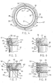
- the container 20 having the seam ring 27 described above is preferred for certain applications, while variations incorporating the essential features of the present invention may be utilized without departing from the spirit and scope of the invention. Such variations are shown in Figs. 5-15 and 17. It is also understood that a feature shown in one figure may appropriately be combined with features shown in other figures of the present invention as desired for a specific applications as will be readily apparent to those of ordinary skill in the art.
- a seam ring 60 in accordance with the invention is shown in Fig. 5 on a container body 61 which has a smooth substantially straight outer surface beneath the double seam 62 by which the metal closure 63 is joined to the container body.
- the seam ring 60 has a top portion 64, an inner skirt 65 and an outer skirt 66.
- Fig. 5 shows another embodiment of the means for securing the seam ring to the container body, inwardly facing bead 67, which is formed on the inner surface of the outer skirt and extends inwardly with a flat top surface 68 directly underneath the outwardly extending bead of the double seam 62.
- the inner surface 69 of the bead 67 is formed to closely match in shape and dimension the adjacent juxtaposed outer surface of the container body 61.
- the inner surface 69 will also be cylindrical.
- the spacing between the outer surface of the container 61 and the inner surface 69 of the seam ring bead is less than the width of a human fingernail, for example, less than twenty thousandths of an inch (0.5 mm), and preferably the two surfaces will be in relatively tight contact to inhibit removal of the seam ring from the body.
- a beveled edge 70 be provided on the outer surface of the bead 67 extending from the bottom edge of the bead to the outer surface of the outer skirt 60 so that it would be difficult for someone to pull or push upwardly on the seam ring at the surface 70 with sufficient force as to remove the seam ring by hand. It is of course more difficult to apply a force to the beveled surface 70 than to a flat horizontal one if such were utilized for the bottom surface of the seam ring.
- adhesive 202 can be employed in any suitable manner between the seam ring and the seam.
- the adhesive can be placed on the seam ring bottom edge, it is preferably placed onto the perimeter of the metal closure 63 to adhere the inner skirt 65 to the closure 63 when the seam ring is snapped into place.
- a hot melt adhesive such as is available commercially under the trademark "Thermogrip”® is a suitable adhesive for many applications.
- a seam ring 75 which has a top portion 76, an inner skirt 77, and an outer skirt 78.
- An inwardly facing bead 79 is formed on the inner surface of the outer skirt 78 near its bottom peripheral edge, having substantially the same shape as the bead 47 of the seam ring 27 of Figs. 1-4.
- the inner skirt 77 of the seam ring 75 is smooth, without a support ledge formed therein for support of a splash panel where such is not desired, although a splash panel can be placed within the seam ring and will, if properly sized, engage at its edges and be supported by the inwardly descending inner skirt wall 77.
- the inner bottom edge 80 of the inner skirt 77 can be tapered such that its lower marginal end portion is tapered to provide the container user with cut edge protection but which facilitates removal of the panel within the parting line.
- the inner bottom edge 80 is spaced at or just above the top surface of the metal closure 81 which is attached by a double seam 82 to the container body 83.
- a protective ledge 85 is formed on the outer surface of the container body 83 and has a horizontally extending top surface 86 spaced just below the bottom edge 87 of the outer skirt 78 when the seam ring is in place shielding and concealing the double seam 82.
- the spacing between the bottom surface 87 of the outer skirt and the top surface 86 of the protective ledge is again preferably less than the thickness of a fingernail.
- the peripheral surface of the protective ledge 85 is also preferably downwardly and inwardly beveled as shown to enhance the appearance of the completed package, to enable easier formation of the plastic container body and to shield and thereby make it more difficult to insert a fingernail or tool between the bead 79 and the container body 83 or between the top edge of the surface 86 of the protective ledge and the bottom 87 of the outer skirt of the seam ring.
- the seam ring 90 shown in Fig. 7 has a top portion 91, an inner skirt 92, an outer skirt 93, and an inwardly extending bead 94 which engages a lower portion of and, preferably under the double seam 95 by which the metal closure 96 is attached to the container body 97.
- the container body has an outwardly extending protective ledge 98 formed in substantially the same manner as the protective ledge 95 described above, and the bead 94 on the outer skirt of the seam ring is formed in the same manner as the bead 79 described above.
- the seam ring 90 may also utilize other means than an inwardly extending bead for engaging an outwardly extending seam, such as those shown in Figs. 1-4 or in Fig. 5.
- the inner skirt 92 has a peripheral channel 100 formed therein, which is defined at the bottom thereof by an inwardly extending support ledge 101, spaced just above the top surface of the flat portion of the closure 96.
- the inner edge of the relatively thin and flexible support ledge 101, defining the inner bottom edge of the inner skirt, may lie inwardly of the parting line 99 in the closure. Because the ledge portion 101 is relatively thin and may be made flexible, it may extend slightly over the area of the closure within the parting line without unduly interfering with removal of this portion of the closure. Of course, a similar flexible bottom edge portion may be formed on other embodiments of the inner skirt to correspondingly allow the skirt to fully cover and protect the metal remaining on the container.
- a splash panel 102 here having a central domed portion 103 and an outwardly extending side portion or lip 104, has the edges of the outwardly extending lip engaged into the channel 100 and supported on top of the ledge 101 at a position just above the closure 96. Because the central portion 103 of the panel 102 is domed and thereby spaced substantially away from the top level of any product (not shown) within the container body beneath the closure 96, the closure will not be dislodged or affected as the product within the container is heated in a microwave oven and gases or splashed product are released therefrom.
- the splash panel 102 can be formed in any suitable shape by a variety of ways, such as by forming plastic sheets or discs or by molding or stamping paperboard in a conventional fashion to assume a dome shape, as is done in the production of paperboard plates and dishes.
- the seam ring 110 shown in Fig. 8 has a top portion generally designated 111, an inner skirt 112, and an outer skirt 113.
- the outer skirt has an inwardly facing bead 114, shaped as described above for the seam rings of Figs. 1-4, which engages against the bottom of the bead of the double seam 115 by which the metal closure 116 is joined to the container body 117.
- a protective ledge 118 is formed on the outer surface of the container body 117 to shield and restrict the removability of the seam ring.
- the top surface of the ledge 118 does not extend out to the outer surface of the outer skirt 113, leaving a portion of the bottom edge of the skirt exposed, which may allow a user to push upwardly on the bottom edge of the skirt with a fingernail.
- the ledge 118 does serve, in accordance with the present invention, to reduce the accessibility of the bottom edge of the skirt and further to shield the bead 114 on the bottom of the skirt from access so that a user cannot readily insert a fingernail between the bead 114 and the adjacent outer surface of the container body 117.
- an adhesive 201 may be applied as desired between the double seam and the inside of the seam ring to partially or completely fill the space therebetween.
- a hot melt adhesive such as that available under the trademark Thermogrip®, is generally preferred.
- a support ledge 120 is formed in the inner surface wall of the seam ring above the descending portion of the inner skirt 112 and forms a horizontal surface preferably continuously about on the seam ring to support the edge portion of a splash panel 121.
- an inward extrusion 122 is provided on all or a portion of the inner surface of the top portion of the seam ring above the support ledge 120 such that a channel 123 is formed between the inward extension 122 and the support ledge 120 which is sized and shaped to hold the splash panel 121 when the splash panel is seated on the support ledge 120.
- the support ledge 120 can be located at any selected suitable distance above the lower inner edge 125 of the inner skirt 112 so that the splash panel will be sufficiently spaced from the content of the container when the removable panel of the closure is removed, to accommodate the expansion of gases from the product within the container during microwave heating.
- the seam ring 130 shown in Fig. 9 is substantially similar but not identical in structure to the seam ring 27 of Fig. 3, having a top portion 131, an inner skirt 132, an outer skirt 133, and an inwardly facing bead 134 on the inner surface of the outer skirt which engages a lower portion of, preferably under, the double seam 135 by which the metal closure 137 is joined to the top of the container body 138.
- a protective ledge 139 extends outwardly from the periphery of the outer surface of the container body just underneath the bottom of the outer skirt to inhibit removability of the seam ring.
- the seam ring 130 also has a support ledge 140 extending about, preferably continuously around, the inner periphery of the seam ring and a plurality of inwardly extending spaced lugs 141 which are shaped and formed in the same manner as the lugs 39 of Figs. 1-4.
- the seam ring 130 additionally has a thin flexible plastic lip 142 integrally formed with and extending upwardly from the support ledge 140, preferably but not necessarily continuously around its entire circumference, at a position just inwardly of the innermost edge of the lugs 141.
- a splash panel (not shown in Fig. 9), which may be identical to the splash panel 37 of Figs.
- the flexible plastic lip is preferably integrally formed with the remainder of the seam ring, such as by an injection molding process, but it is of a sufficiently small thickness that it will be quite flexible and can deflect under the pressures applied as a splash panel is engaged under the lugs 141.
- the seam ring 150 of Fig. 10 substantially identical in structure to the seam ring 27 of Fig. 3, has a top portion 151, a descending inner skirt 152, an outer skirt 153, an inwardly facing bead 154 on the outer skirt, a support ledge 155 formed on the inner surface of the seam ring around its periphery, and a plurality of engagement lugs 156 extending over the support ledge.
- a splash panel 158 is shown inserted into place and held between the top surface of the support ledge 155 and the lugs 156.
- the splash panel 158 which may be made of any suitable material, is here shown as comprised of a substantially rigid, flat substrate layer 159, such as paperboard, and a compressible layer 160 such as a soft, compressible, foamed plastic layer 160 laminated to one surface of the layer 159.
- the foam should be of the closed cell type to resist penetration by liquid.
- a suitable foam is available commercially under the trademark Volara® which is a crosslinked polyethylene foam.
- the rigid layer 159 may be formed of relatively rigid plastic, metal foil, paper, paperboard, cardboard, and a combination of the same. These materials may, of course, also be used for the single layer splash panel described above. Other or more layers may be employed.
- an additional coating layer may be employed below the foam layer to prevent it from absorbing substances such as splashed liquid or food. Coatings may also be employed on single layer splash panels.
- the total thickness of the splash panel 158 is preferably slightly greater than the distance between the bottom surface of the engagement lugs 156 and the top surface of the support ledge 155 such that the foamed plastic layer 160 is compressed as the edges of the splash panel 158 are inserted into position between the lugs 156 and the support ledge, as illustratively shown in Fig. 10.
- the substantially tight sealing engagement provided by the compression of the foam layer as the splash panel is locked into place provides a substantially liquid-tight seal of the splash panel to the seam ring, allowing the seam ring to be used when it is desired to completely seal the top of the container and prevent any liquid from spilling from the container even if the container is tilted slightly.
- the compressible splash panel 158 may also be utilized with any of the other seam ring embodiments of the present invention, especially those which hold a splash panel in place and restrict upward removal, such as those shown in Figs. 7, 8, and 9.
- a container 170 in accordance with the present invention shown in Fig. 11 has a container body 171, the position of which is shown in dashed lines for simplicity of illustration and which may be formed generally as described above, and a metal closure 172, the general position of which only is illustrated, joined to the top of the container body 171 preferably by a double seam (not shown in Fig. 11).
- the double seam is concealed by a seam ring 175 which may generally be formed in a manner which enables it to be secured to the top of the container body such as in the manner described above for the seam rings of Figs. 1-10.
- any of the various constructions for the seam ring including those described above which support and hold the splash panel in place may be utilized if it is desired to have a splash panel.
- the seam ring 175 of Fig. 11 is further distingushed by havng a pair of integrally formed fixed handles 176 extending outwardly from opposite sides of the periphery of the seam ring. In the embodiment of Fig.
- the handles 176 are formed as rigid tabs, having substantially the shape of a portion of an oval, although the handles, which may be provided on or in conjunction with the seam ring, may have any other configuration or construction as desired by which the handles extend or and extendable outwardly beyond the normal outer periphery of the seam ring as defined by the outside surface of the outer skirt. As shown in the cross sectional view of Fig.
- the handles 176 which is taken through one of the handles 176, the seam ring as a top portion 177, an inner skirt 178, an outer skirt 179, an inwardly facing bead 180 by which the seam ring may be secured to the container by engaging against or under a seam, and the outwardly extending handle 176 which is formed as an extension of the top portion 177 of the seam ring and which is reinforced by a vertical rib or web 181.
- the handles 176 are preferably integrally formed with the seam ring, preferably by an injection molding process.
- the handles allow the consumer to remove a hot container such as a container with a hot liquid or foodstuff in it, from the microwave oven by grasping the two handles with both hands and withdrawing the container from the microwave oven.
- handles 176 are not in direct contact with the container body they are not heated by the contents of the container and, as they are formed of plastic, they do not generally become heated themselves by microwaves.
- a single handle, or more than two handles, or a handle which effectively circumscribes the entire periphery of the seam ring, may also be utilized in accordance with the invention.
- a seam ring 175 having one or more handles 176 be relatively strongly secured to the top of the container body so that the container does not slip out from the seam ring as the consumer is lifting, withdrawing or carrying the container from the microwave oven by holding the handles.
- the closely-shaped fit of the outer skirt inner surface relative to the seam, and the inwardly extending bead on the outer skirt of the seam ring which preferably tightly engages the seam ring against the outwardly extending bead formed by the double seam, thereby relatively tightly and nonremovabaly secures the seam ring to the container.
- the seam ring is "non-removably secured" to the container body if it cannot be removed by the hand of the consumer without the use of a tool or extraordinary effort. Because of the heating of the container during microwaving, and to some degree the heating of the inner and outer skirts of the seam ring, it is particularly preferred that the material forming the seam ring 175 having handles 176 remain rigid even when heated to temperatures ordinarily experienced within the microwave oven, e.g., up to the boiling point of water. It has been found that relatively heat stable plastic materials such as nylon and PET are particularly suited to such applications.
- plastic is to be broadly construed herein; for example, it is to include suitable polymeric materials other than thermoplastic which perform in accordance with functions and objectives of this invention.
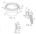
- the container 190 of Fig. 13 has a container body 191, again shown in phantom by dashed lines and which may be formed generally as described above, and a seam ring 192 attached to the top of the container body which may have any of the structures for the seam ring described above.
- the seam ring 192 further includes a pair of foldable handles 194 which extend outwardly from opposite sides of the outer periphery of the seam ring.
- the seam ring 192 has a top portion 195, an inner skirt 196, an outer skirt 197, and an inwardly facing bead 198 on the outer skirt as previously described.
- the foldable handles 194 are preferably integrally formed as part of the seam ring 192 and are connected to the outer skirt 197 of the seam ring by a thin plastic living hinge 199.
- a top view of the edge of the seam ring with one of the handles 194 extending therefrom-- a pair of the "living hinges" 199 are utilized which extend from two positions through two integral webs on the periphery of the seam ring to the back edge of the handle 194.
- the handles 194 are preferably folded downwardly.
- the consumer can lift the handles upwardly, causing the back surface 200 of each handle to engage against the outer surface of the outer skirt 197, thereby stopping further upward rotation of the handles and providing a rigid outwardly extending handle by which the consumer can grasp the container and remove it from the microwave oven after heating.
- the handles 194 will remain relatively cool and will allow the consumer to remove the container from the microwave oven without having to make contact with the heated container body.
- the material of the seam ring 192 be chosen of a plastic which is relatively heat stable and retains relatively high rigidity at elevated temperatures, such as nylon and PET, although other plastics having less rigidity at elevated temperatures may also be used where further means are employed, such as adhesive, to secure the seam ring to the top of the container body.
- a seam ring 210 is shown in Fig. 17 which is substantially identical to the seam ring 27 of Figs. 1-4, having a top portion 211, an outer skirt 212 with an inwardly facing bead 213, an inner skirt 214 with bottom edge 215, and extending lugs 216 formed over a support ledge 217.
- the container body 218 has a protecting ledge 219 formed beneath the bottom of the outer skirt and an outwardly extending bead 220 formed at the top peripheral edge of the container body and under which the bead 213 is engaged.
- a closure 221 formed of a non-peelable polymer coated aluminum foil is heat sealed at a seam 222 to the container body and may also be heat sealed to the inner surface of the inner skirt of the seam ring.
- a parting line may be formed in the closure in a known manner directly under or adjacent to the bottom edge 215 of the seam ring so that the seam ring substantially conceals all portions of the closure remaining after the area within the parting line is removed.
Landscapes
- Engineering & Computer Science (AREA)
- Mechanical Engineering (AREA)
- Life Sciences & Earth Sciences (AREA)
- Food Science & Technology (AREA)
- Closures For Containers (AREA)
- Package Specialized In Special Use (AREA)
- Rigid Containers With Two Or More Constituent Elements (AREA)
- Containers Opened By Tearing Frangible Portions (AREA)
Applications Claiming Priority (2)
| Application Number | Priority Date | Filing Date | Title |
|---|---|---|---|
| US100293 | 1987-09-22 | ||
| US07/100,293 US4940158A (en) | 1987-09-22 | 1987-09-22 | Container and seam ring for container |
Publications (2)
| Publication Number | Publication Date |
|---|---|
| EP0309189A2 true EP0309189A2 (fr) | 1989-03-29 |
| EP0309189A3 EP0309189A3 (fr) | 1990-07-25 |
Family
ID=22279053
Family Applications (1)
| Application Number | Title | Priority Date | Filing Date |
|---|---|---|---|
| EP88308685A Withdrawn EP0309189A3 (fr) | 1987-09-22 | 1988-09-20 | Récipient et anneau de recouvrement pour son bord serti |
Country Status (4)
| Country | Link |
|---|---|
| US (1) | US4940158A (fr) |
| EP (1) | EP0309189A3 (fr) |
| JP (1) | JPH01167081A (fr) |
| CA (1) | CA1312306C (fr) |
Cited By (2)
| Publication number | Priority date | Publication date | Assignee | Title |
|---|---|---|---|---|
| DE3935201A1 (de) * | 1989-10-23 | 1991-05-02 | Schmalbach Lubeca | Verpackung |
| CN113415538A (zh) * | 2021-06-06 | 2021-09-21 | 赣州睿农果业开发有限公司 | 一种食品绿色储运的储运装置用清理设备及清理方法 |
Families Citing this family (45)
| Publication number | Priority date | Publication date | Assignee | Title |
|---|---|---|---|---|
| USD352239S (en) | 1991-08-08 | 1994-11-08 | Sweetheart Cup Company, Inc. | Beverage can-carrying device |
| US5285892A (en) * | 1991-08-08 | 1994-02-15 | Sweetheart Cup Company Inc. | Sanitary can carriers and multiple beverage can packages including the same |
| USD356733S (en) | 1992-05-12 | 1995-03-28 | Sweetheart Cup Company Inc. | Beverage can-carrying device |
| USD345081S (en) | 1992-06-09 | 1994-03-15 | Sweetheart Cup Company Inc. | Combined splash guard lid and carrier for multiple microwavable food containers |
| USD354227S (en) | 1992-08-05 | 1995-01-10 | Sweetheart Cup Company Inc. | Beverage can-carrying device |
| FR2710033B1 (fr) * | 1993-09-17 | 1995-11-17 | Oreal | Elément de fermeture pour emprisonner un produit dans un pot de manière inviolable et procédé de fabrication d'un tel élément de fermeture. |
| US5507406A (en) * | 1994-04-26 | 1996-04-16 | Belford Patrick, Inc. | Tamperproof/tamper evident container |
| CA2181604C (fr) * | 1995-07-20 | 2008-02-05 | Kenji Shachi | Element de fermeture et d'etancheite |
| US5593610A (en) * | 1995-08-04 | 1997-01-14 | Hormel Foods Corporation | Container for active microwave heating |
| US5780824A (en) * | 1997-02-07 | 1998-07-14 | Lulirama International, Inc. | Expandable and self-venting novelty container for cooking microwavable popcorn |
| USD405692S (en) | 1998-04-20 | 1999-02-16 | Johnson Robert W | Floating cover |
| US6802418B2 (en) * | 2001-04-06 | 2004-10-12 | Daphne Elmaleh Zohar | Compact packaging for garments made from delicate materials |
| US7055713B2 (en) * | 2002-11-12 | 2006-06-06 | Sonoco Development, Inc. | Easy-opening closure for retortable container |
| CN100393589C (zh) * | 2003-03-18 | 2008-06-11 | 沃纳·格雷伯 | 包括箔密封件的罐桶 |
| ATE431395T1 (de) * | 2003-03-31 | 2009-05-15 | Becton Dickinson Co | Fluidabdichtung für laborbehälter |
| US7112771B2 (en) * | 2004-03-09 | 2006-09-26 | Ball Corporation | Microwavable metallic container |
| US7378625B2 (en) * | 2004-03-09 | 2008-05-27 | Ball Corporation | Microwavable metallic container |
| US8080770B2 (en) * | 2004-03-09 | 2011-12-20 | Ball Corporation | Microwavable metallic container |
| US20070181577A1 (en) * | 2006-02-08 | 2007-08-09 | Huhtamaki Foodservice, Inc. | Container |
| US20100072217A1 (en) * | 2008-09-19 | 2010-03-25 | Par-Pak Ltd. | Tamper evident container with frangible closure member |
| GB2464819B (en) | 2008-10-28 | 2012-10-24 | Par Pak Ltd | Tamper-evident container with frangible hinge |
| US20100237068A1 (en) * | 2009-03-17 | 2010-09-23 | Rubbermaid Incorporated | Container With In-Molded Exposed Panel |
| US8272862B2 (en) * | 2009-05-29 | 2012-09-25 | L'oreal Sa | Article and method for fabricating an applicator tip assembly for a skin formulation applicator |
| DE202010003547U1 (de) * | 2010-03-15 | 2010-07-08 | Mars Incorporated | Stapelbare Dose mit Deckel |
| USD654791S1 (en) * | 2010-09-11 | 2012-02-28 | Benson Iii Lawrence Duffy | Printable piece for a pull-top can |
| US8939695B2 (en) | 2011-06-16 | 2015-01-27 | Sonoco Development, Inc. | Method for applying a metal end to a container body |
| JP2013033688A (ja) * | 2011-08-03 | 2013-02-14 | Sharp Corp | 二次電池 |
| US8998027B2 (en) | 2011-09-02 | 2015-04-07 | Sonoco Development, Inc. | Retort container with thermally fused double-seamed or crimp-seamed metal end |
| US10131455B2 (en) | 2011-10-28 | 2018-11-20 | Sonoco Development, Inc. | Apparatus and method for induction sealing of conveyed workpieces |
| US10399139B2 (en) | 2012-04-12 | 2019-09-03 | Sonoco Development, Inc. | Method of making a retort container |
| US20130323399A1 (en) * | 2012-06-05 | 2013-12-05 | Andrew Brian Davis | Processed Garlic Formulation |
| US9446890B1 (en) * | 2012-10-08 | 2016-09-20 | Glenn H. Morris, Jr. | Rectangular pail with locking lid |
| USD767330S1 (en) * | 2015-03-02 | 2016-09-27 | Lodge Manufacturing Company | Set of lid handles |
| US10583958B2 (en) * | 2015-03-04 | 2020-03-10 | Compagnie Generale De Conserve | Container for preserved food with a flexible bottom, and corresponding production method |
| USD844768S1 (en) * | 2017-09-06 | 2019-04-02 | Rheem Manufacturing Company | Water heater top cap assembly |
| US11091304B2 (en) * | 2018-01-02 | 2021-08-17 | Owens-Brockway Glass Container Inc. | Container closure with vacuum-indicating pull tab |
| EP3817987B1 (fr) * | 2018-07-05 | 2024-01-10 | Mölnlycke Health Care AB | Récipient pour fluide |
| USD947675S1 (en) | 2018-12-17 | 2022-04-05 | Kikuo Yamada | Lid for a cup |
| JP2020132252A (ja) * | 2019-02-25 | 2020-08-31 | 大和製罐株式会社 | 缶蓋 |
| WO2021217125A1 (fr) * | 2020-04-24 | 2021-10-28 | Rba Enterprises, Llc | Récipient et couvercle avec joint de protection |
| USD980069S1 (en) | 2020-07-14 | 2023-03-07 | Ball Corporation | Metallic dispensing lid |
| US12168551B2 (en) | 2021-03-01 | 2024-12-17 | Ball Corporation | Metal container and end closure with seal |
| USD1003725S1 (en) | 2021-09-03 | 2023-11-07 | Graham Packaging Company, L.P. | Container |
| USD1010454S1 (en) | 2021-09-03 | 2024-01-09 | Graham Packaging Company, L.P. | Container |
| EP4656546A1 (fr) * | 2024-05-31 | 2025-12-03 | Sabert Corporation Europe | Couvercle d'un récipient pour aliments ou boissons, récipient, méthode d'emballage d'aliments ou de boissons et méthode de fabrication d'un couvercle ou d'un récipient |
Family Cites Families (48)
| Publication number | Priority date | Publication date | Assignee | Title |
|---|---|---|---|---|
| US2259856A (en) * | 1939-04-27 | 1941-10-21 | Richard D Moore | Sanitary guard for beverage bottles |
| US2615610A (en) * | 1947-12-26 | 1952-10-28 | American Can Co | Container with reclosure and shield device |
| US2614406A (en) * | 1950-04-24 | 1952-10-21 | Oliver W Carpenter | Drinking rim for beer cans |
| US2753049A (en) * | 1951-12-10 | 1956-07-03 | Gaines Bernard | Strainer-protector for drinking vessels |
| US2860814A (en) * | 1955-05-24 | 1958-11-18 | Crown Cork & Seal Co | Container |
| US2999559A (en) * | 1958-04-04 | 1961-09-12 | Samuel D Boyer | Splatter guard for frying pans and the like |
| US3101857A (en) * | 1962-01-18 | 1963-08-27 | Jayme Products Inc | Attachments for commodity jars and glasses |
| US3185341A (en) * | 1962-05-14 | 1965-05-25 | Richard T Barbour | Attachment for drinking canned beverages |
| US3208627A (en) * | 1963-04-15 | 1965-09-28 | Nat Can Corp | Reclosable can |
| US3214074A (en) * | 1963-09-03 | 1965-10-26 | Phillips Petroleum Co | Container provided with cover seal and removable inner lid |
| US3310195A (en) * | 1964-01-29 | 1967-03-21 | Continental Can Co | Plastic body and container attachment to end of can |
| US3253733A (en) * | 1964-01-31 | 1966-05-31 | Reynolds Metals Co | Easy open container and method |
| US3309000A (en) * | 1965-04-13 | 1967-03-14 | Virgil L Haverstick | Can extender and pourer |
| US3401819A (en) * | 1967-03-22 | 1968-09-17 | Joseph P. Salamone | Container opening caps |
| US3419181A (en) * | 1967-11-07 | 1968-12-31 | Continental Can Co | Score guard overcap for full open ends |
| DE1817502A1 (de) * | 1968-01-03 | 1969-07-31 | Rene Dru | Zusatzdeckel mit eingelegtem und herausnehmbarem Handgriff fuer Konservendosen oder aehnliche Behaelter |
| AT278711B (de) * | 1968-04-30 | 1970-02-10 | H C Hans Dipl Ing Dr Dr List | Meßeinrichtung zur Bestimmung des O2- und des CO2-Partialdruckes sowie des pH-Wertes einer Blutprobe |
| US3805993A (en) * | 1970-04-14 | 1974-04-23 | Gen Foods Corp | Closure for metal container |
| US3717276A (en) * | 1971-02-12 | 1973-02-20 | Owens Illinois Inc | Vented closure |
| US3765561A (en) * | 1972-03-10 | 1973-10-16 | Continental Can Co | Easy opening container provided with opening edge protective hot melt adhesive band |
| US3836041A (en) * | 1972-06-14 | 1974-09-17 | Umc Ind | Container skirt |
| US3930607A (en) * | 1975-01-20 | 1976-01-06 | Phillips Petroleum Company | Container and blanks therefor |
| US4030630A (en) * | 1975-06-18 | 1977-06-21 | Penland Container, Inc. | All plastic reclosable container closure |
| NL185713C (nl) * | 1975-09-12 | 1990-07-02 | Akerlund & Rausing Ab | Werkwijze voor het vervaardigen van gasdichte kunststof houder. |
| US4004710A (en) * | 1975-12-31 | 1977-01-25 | Mammoth Plastics, Inc. | Container and closure therefor |
| US4133996A (en) * | 1977-02-15 | 1979-01-09 | Fread Ronald G | Microwave oven egg cooking apparatus |
| US4163374A (en) * | 1977-12-21 | 1979-08-07 | Freeze Sleeves Of America, Inc. | Refrigeratable beverage container holder |
| US4143785A (en) * | 1978-03-16 | 1979-03-13 | Sun Coast Plastic Closures, Inc. | Plastic vacuum sealing cap |
| GB2025888B (en) * | 1978-07-19 | 1982-09-08 | Snow Brand Milk Products Co Ltd | Container |
| DE2928000A1 (de) * | 1978-07-26 | 1980-02-21 | Tokan Kogyo Co Ltd | Muehelos zu oeffnendes deckelteil |
| US4308970A (en) * | 1978-11-27 | 1982-01-05 | Holdt J W Von | Plastic bucket defining annular inwardly projecting ridge |
| US4278178A (en) * | 1979-05-21 | 1981-07-14 | Kerr Glass Manufacturing Corporation | Child-resistant closure and container |
| US4526821A (en) * | 1979-07-20 | 1985-07-02 | American Can Company | Multi-layer container and method of making same |
| US4266689A (en) * | 1979-10-01 | 1981-05-12 | Phillips Petroleum Company | Closure for top inside roll container |
| US4245753A (en) * | 1979-10-04 | 1981-01-20 | Ellis Henry D | Container for paint |
| US4407897A (en) * | 1979-12-10 | 1983-10-04 | American Can Company | Drying agent in multi-layer polymeric structure |
| US4293080A (en) * | 1980-07-16 | 1981-10-06 | Letica Corporation | Container construction |
| US4448345A (en) * | 1982-07-29 | 1984-05-15 | Container Corporation Of America | Composite lid |
| US4518651A (en) * | 1983-02-16 | 1985-05-21 | E. I. Du Pont De Nemours And Company | Microwave absorber |
| DE8318510U1 (de) * | 1983-06-25 | 1983-10-06 | Brändlein, Manfred, 8500 Nürnberg | Verschluss fuer Getraenkedosen o dgl |
| DK149152C (da) * | 1983-07-28 | 1986-09-15 | Jens Ove Nielsen | Salgsemballage af dunk- eller baegertypen samt med laag og sikkerhedslukke |
| JPS6092931U (ja) * | 1983-12-02 | 1985-06-25 | 北海製罐株式会社 | 簡易開口容器 |
| NL8401729A (nl) * | 1984-05-29 | 1985-12-16 | Thomassen & Drijver | Inrichting voor het opnemen van voedsel. |
| US4640838A (en) * | 1984-09-06 | 1987-02-03 | Minnesota Mining And Manufacturing Company | Self-venting vapor-tight microwave oven package |
| US4560850A (en) * | 1984-12-03 | 1985-12-24 | Aluminum Company Of America | Container with steam port for use in microwave ovens |
| US4572393A (en) * | 1985-02-25 | 1986-02-25 | Hokkai Can Co., Ltd. | Container with easy open type closure |
| US4632272A (en) * | 1985-03-22 | 1986-12-30 | Berenfield/Midwest Corporation | Lid structure having fastening means |
| US4619373A (en) * | 1985-10-04 | 1986-10-28 | Galer Herbert W | Plastic paint container |
-
1987
- 1987-09-22 US US07/100,293 patent/US4940158A/en not_active Expired - Fee Related
-
1988
- 1988-09-20 EP EP88308685A patent/EP0309189A3/fr not_active Withdrawn
- 1988-09-21 CA CA000578048A patent/CA1312306C/fr not_active Expired - Fee Related
- 1988-09-22 JP JP63238627A patent/JPH01167081A/ja active Pending
Cited By (3)
| Publication number | Priority date | Publication date | Assignee | Title |
|---|---|---|---|---|
| DE3935201A1 (de) * | 1989-10-23 | 1991-05-02 | Schmalbach Lubeca | Verpackung |
| US5152418A (en) * | 1989-10-23 | 1992-10-06 | Schmalbach-Lubeca Ag | Container with sealed closure |
| CN113415538A (zh) * | 2021-06-06 | 2021-09-21 | 赣州睿农果业开发有限公司 | 一种食品绿色储运的储运装置用清理设备及清理方法 |
Also Published As
| Publication number | Publication date |
|---|---|
| JPH01167081A (ja) | 1989-06-30 |
| CA1312306C (fr) | 1993-01-05 |
| US4940158A (en) | 1990-07-10 |
| EP0309189A3 (fr) | 1990-07-25 |
Similar Documents
| Publication | Publication Date | Title |
|---|---|---|
| US4940158A (en) | Container and seam ring for container | |
| US4890759A (en) | Retortable container with easily-openable lid | |
| CA1042838A (fr) | Emballage pouvant etre scelle et sterilise | |
| CA2083368C (fr) | Contenant jetable pour cuisson au four a micro-ondes | |
| US4974742A (en) | Container with foldable handles | |
| US5348181A (en) | Winged cup lid | |
| CA1062661A (fr) | Contenant pouvant etre ferme hermetiquement et sterilise | |
| CA2640610C (fr) | Plateau a ustensile integre | |
| US4848931A (en) | Packaging sheet and containers and pouches using the sheet | |
| US4756917A (en) | Packaging sheet and containers and pouches using the sheet | |
| CA2346399C (fr) | Recipient | |
| US5992674A (en) | Tray and two part cover for easy opening and handling | |
| WO1999059897A2 (fr) | Recipient pour produits alimentaires | |
| CA2054683A1 (fr) | Contenant d'emballage | |
| US4993577A (en) | Containers | |
| WO1999019226A1 (fr) | Emballage refermable pour produits alimentaires | |
| JPH0331714Y2 (fr) | ||
| GB2369341A (en) | A heat responsive food product container | |
| JPH05139437A (ja) | 蓋付き包装用容器 | |
| EP0284137B1 (fr) | Emballage | |
| CA1266012A (fr) | Structure arrachable | |
| GB2410245A (en) | Cover for a drinking vessel having a separate compartment | |
| WO2003018420A1 (fr) | Boite refermable et sterilisable en autoclave | |
| JPS63110175A (ja) | 包装用容器の蓋 | |
| JP2001114341A (ja) | 惣菜等食品用の合成樹脂製容器 |
Legal Events
| Date | Code | Title | Description |
|---|---|---|---|
| PUAI | Public reference made under article 153(3) epc to a published international application that has entered the european phase |
Free format text: ORIGINAL CODE: 0009012 |
|
| AK | Designated contracting states |
Kind code of ref document: A2 Designated state(s): AT BE CH DE ES FR GB GR IT LI LU NL SE |
|
| RAP1 | Party data changed (applicant data changed or rights of an application transferred) |
Owner name: AMERICAN NATIONAL CAN COMPANY |
|
| PUAL | Search report despatched |
Free format text: ORIGINAL CODE: 0009013 |
|
| AK | Designated contracting states |
Kind code of ref document: A3 Designated state(s): AT BE CH DE ES FR GB GR IT LI LU NL SE |
|
| 17P | Request for examination filed |
Effective date: 19901219 |
|
| 17Q | First examination report despatched |
Effective date: 19920203 |
|
| STAA | Information on the status of an ep patent application or granted ep patent |
Free format text: STATUS: THE APPLICATION HAS BEEN WITHDRAWN |
|
| 18W | Application withdrawn |
Withdrawal date: 19921210 |