EP0309193A2 - Kartenleser - Google Patents
Kartenleser Download PDFInfo
- Publication number
- EP0309193A2 EP0309193A2 EP88308691A EP88308691A EP0309193A2 EP 0309193 A2 EP0309193 A2 EP 0309193A2 EP 88308691 A EP88308691 A EP 88308691A EP 88308691 A EP88308691 A EP 88308691A EP 0309193 A2 EP0309193 A2 EP 0309193A2
- Authority
- EP
- European Patent Office
- Prior art keywords
- card
- spring
- card reader
- reader
- reading
- Prior art date
- Legal status (The legal status is an assumption and is not a legal conclusion. Google has not performed a legal analysis and makes no representation as to the accuracy of the status listed.)
- Withdrawn
Links
Images


Classifications
-
- G—PHYSICS
- G06—COMPUTING OR CALCULATING; COUNTING
- G06K—GRAPHICAL DATA READING; PRESENTATION OF DATA; RECORD CARRIERS; HANDLING RECORD CARRIERS
- G06K7/00—Methods or arrangements for sensing record carriers, e.g. for reading patterns
-
- G—PHYSICS
- G07—CHECKING-DEVICES
- G07C—TIME OR ATTENDANCE REGISTERS; REGISTERING OR INDICATING THE WORKING OF MACHINES; GENERATING RANDOM NUMBERS; VOTING OR LOTTERY APPARATUS; ARRANGEMENTS, SYSTEMS OR APPARATUS FOR CHECKING NOT PROVIDED FOR ELSEWHERE
- G07C9/00—Individual registration on entry or exit
- G07C9/00174—Electronically operated locks; Circuits therefor; Nonmechanical keys therefor, e.g. passive or active electrical keys or other data carriers without mechanical keys
- G07C9/00658—Electronically operated locks; Circuits therefor; Nonmechanical keys therefor, e.g. passive or active electrical keys or other data carriers without mechanical keys operated by passive electrical keys
- G07C9/00722—Electronically operated locks; Circuits therefor; Nonmechanical keys therefor, e.g. passive or active electrical keys or other data carriers without mechanical keys operated by passive electrical keys with magnetic components, e.g. magnets, magnetic strips, metallic inserts
-
- G—PHYSICS
- G06—COMPUTING OR CALCULATING; COUNTING
- G06K—GRAPHICAL DATA READING; PRESENTATION OF DATA; RECORD CARRIERS; HANDLING RECORD CARRIERS
- G06K7/00—Methods or arrangements for sensing record carriers, e.g. for reading patterns
- G06K7/08—Methods or arrangements for sensing record carriers, e.g. for reading patterns by means detecting the change of an electrostatic or magnetic field, e.g. by detecting change of capacitance between electrodes
- G06K7/082—Methods or arrangements for sensing record carriers, e.g. for reading patterns by means detecting the change of an electrostatic or magnetic field, e.g. by detecting change of capacitance between electrodes using inductive or magnetic sensors
- G06K7/083—Methods or arrangements for sensing record carriers, e.g. for reading patterns by means detecting the change of an electrostatic or magnetic field, e.g. by detecting change of capacitance between electrodes using inductive or magnetic sensors inductive
- G06K7/084—Methods or arrangements for sensing record carriers, e.g. for reading patterns by means detecting the change of an electrostatic or magnetic field, e.g. by detecting change of capacitance between electrodes using inductive or magnetic sensors inductive sensing magnetic material by relative movement detecting flux changes without altering its magnetised state
Definitions
- the present invention relates to magnetic card readers for reading data from cards or badges such as employee badges or key cards for electronic locks.
- the reader "reads" the data from the card, and supplies the data to a device in which the data is used, such as an electronic door lock, a computer or an encoding or recording device.
- U.S. 4 126 780 describes an optical card reader which has a spring to bias the card away from the light detector and a photo-electric bottom detector to produce a signal when the card reaches the bottom of the reader.
- U.S. 4 519 228 describes an electronic recodable lock which includes a magnetic or optical card reader.
- the card reader includes a lever activated switch which turns on the reading head when the key is inserted into the slot and an end switch which turns the reading head off when the key reaches the end of the slot.
- U.S. 3 896 293 describes a card reader having a constant velocity card transport mechanism. This reader uses a cantilever spring to urge a roller which contacts the card towards the read head so that the coded portion of the card will be forced against the read head.
- Re 29846 describes an electronic lock system which includes a key card reader. This card reader contains a microswitch to activate the read sensors after the card has been fully inserted.
- U.S. 3 622 991 describes an electronic locking system which includes an optical card reader system.
- This card reader uses a shutter which is capable of limited pivotal movement to insure correct orientation of the key card in the slot.
- the present invention provides a magnetic card reader which comprises a cover, a slot in the cover to accept a card, a magnetic reading head movably mounted within the cover, characterised in that the reader further comprises a first switch means positioned within the cover to initiate entry reading of the card, a second switch means positioned within the cover to terminate entry reading of the card and to initiate withdrawal reading of the card, and a spring means responsive to the insertion of the card to actuate the first and second switch means, the spring means having the reading head attached thereto.
- the present invention further provides a spring for a magnetic card reader characterised in that it comprises a base and two arms attached thereto; one arm being adapted to bias a read head toward a magnetic card; the other arm being adapted to actuate two microswitches; the fist microswitch being actuated as the card initially enters the reader and the second microswitch being actuated when the card reaches the end of its travel.
- a card reader according to the present invention is particularly suitable for those applications which compare the data read to stored data and produces a "go" signal if they match and a "no-go” signal if they do not.
- Examples of these applications are electronic door locks where the lock is opened if the data matches but remains locked if it does not.
- Other examples include card readers for employee badges and the like where attendance or the details of a night watchman's rounds are recorded or encoders in which a card is encoded with data and then the encoded data is checked against stored data.
- the card reader accomplishes the dual reading function by means of a simple and inexpensive spring device.
- the spring is formed to include two arms. One arm supports the read head and biases it toward the card.
- the other arm contains two pivot points so that when the card is initially inserted a portion of the spring will deflect and thus activate a first microswitch which in turn activates the reading head and the corresponding electronic and logic circuitry.
- a first microswitch which in turn activates the reading head and the corresponding electronic and logic circuitry.
- the second microswitch signals that the insert reading has ended and that the withdrawal reading should begin.
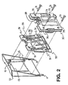
- a preferred embodiment of the card reader according to the present invention includes an external housing or cover 10. Two protruding arms 11 and 12 are positioned to be received by the apparatus in which the card reader is employed. A slot 13 is positioned horizontally in the external cover 10. The slot is sized to accept a card 20 which contains a magnetic strip 21.
- a card reader spring 50 and electronic module 30 are attached to the inside of the cover 10 by means of screws 31 through holes 35 of the electronic module and through holes 51 of the spring 50.
- the screws attach into threaded holes 15 in bosses on the inside of the cover 10.
- the card reader is secured to the apparatus in which it is employed by screw means into a threaded hole 16.
- a magnetic read head 55 is attached to one arm of the card reader spring 50 by means of a suitable adhesive, for example and an anaerobic or moisture curable adhesive. Supports 56 and 57 are provided for structural rigidity.
- the read head 55 may be any suitable magnetic strip reader.
- the read head is connected to the electronic module by means of wires 39 or flexible circuit strip (not shown).
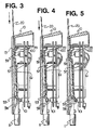
- FIG. 3 the card 20 is positioned immediately outside the slot 13.
- a microswitch 100 is in an open or "off" position.
- the spring 50 deflects and depresses a lever 99 and thus actuates the microswitch 100, which activates the entire electronic module as well as the read head.
- Figure 4 shows the microswitch 100 in a depressed or "on” position. The read head reads data contained on the card 20 as the card 20 continues down the passage.
- the card 20 encounters a raised portion 59 of the spring 50 as is shown in Figure 5.
- the spring 50 deflects, depresses the lever 98 and thus actuates a microswitch 101.
- Figure 5 shows the microswitch 101 in a depressed or "on" position. The microswitch 101 signals to the electronic circuitry that the insert reading has ended and that withdrawal reading should begin.
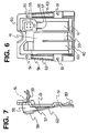
- the configuration of card reader spring 50 will be explained in greater detail with reference to Figures 6 and 7.
- the spring 50 has a frame or base portion to which two arms 60 and 61 are attached.
- the base of the spring can accommodate one or more indented areas 62 and 63 for structural rigidity.
- the right arm 61 is generally rectangular and is attached to the base of the spring.
- the reading head 55 is attached to the right arm 61 at the end opposite to the attachment to the base.
- the right arm 61 is biassed toward the external cover 10 of the card reader and is responsive to insertion of the card. In particular the right arm 61 is adapted to urge the read head 55 towards the card 20.
- the left arm 60 is generally shaped like a small "h" with only the lower left portion of the h being attached to the base of the spring.
- the left arm 60 includes two pivot points which allows it to perform two functions. The approximate locations of the pivot points are identified by the numbers 40 and 41.
- the upper portion of the left arm of the spring has an indented configuration with a crown 58 located at the top of the h. The indented configuration and crown 58 are depicted in side view in Figure 7.
- the lower right portion of the h-shaped left arm contains another raised portion identified by the numeral 59.
- the microswitch 100 is located under the crown 58 and the microswitch 101 is located under the raised portion 59 ot the left arm 60 of the spring 50.
- the left arm 60 of the spring 50 is also responsive to the insertion of the card. In particular, the left arm 60 is biassed away from the microswitches 100 and 101 and toward the external cover 10 of the card reader.
- the spring 50 can be made of any suitable material but is preferably made of a plastic such as that sold under the Trademark Lexan by General Electric. Other materials with equivalent or similar properties may also be employed.
- the spring may be manufactured by any suitable method but is preferably made by injection moulding.
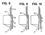
- the read head can thus read data encoded on the magnetic strip 21 as soon as it is pushed past the centre of the read head 55.
- This feature allows data to be encoded along the entire length of the magnetic strip 21.
- the card 20 has not yet encountered the raised portion 59 of the left arm 60. Accordingly, the raised portion 59 has not yet deflected and the microswitch 101, which is located beneath the raised portion 59, has not yet been actuated.
- the card 20 has been inserted to the fullest extent. As it was inserted past the read head 55, the read head was reading the information encoded on the magnetic strip 21. Toward the end of its travel, the card encountered the raised portion 59. The spring 50 is biassed away from the microswitch 101. As the card 20 contacted the raised portion, it pushed it to the right, thus depressing the lever 98 of the microswitch located beneath the raised portion 59. This in turn actuates the microswitch 101.
- the microswitch 101 When the microswitch 101 is actuated, the microswitch 100 is still engaged and thus the read head 55 is still activated.
- the microswitch 101 performs two functions. First, the microswitch 101 signals to the logic circuit that the travel of the card 20 has been completed, so that the information read by the read head 55 can be transmitted to the logic circuitry where it can be compared with the information stored therein to determine if the information matches and the lock can be opened. If a match were found, the lock would be opened. Frequently, however, when inserting the card, the read head does not properly read the data and thus sends incorrect information to the logic circuitry, resulting in no match and the lock not being opened. In this situation, the user must remove the card and try again.
- the present card reader provides a novel approach in which the microswitch 101 signals to the logic circuit to begin accepting information from a second reading, as the card is withdrawn.
- the second function of the microswitch 101 is to initiate the withdrawal reading.
- the reader incorrectly reads the information on insertion of the card, it is given another chance to reread the information as the card is withdrawn.
- the user of the system is given two chances each time the card is inserted, thus improving the probability of a correct read and opening of the door if the data matches.
- the electronic module 30 contains the electronic and logic circuitry to operate the reader.
- the module may contain circuitry to operate a device such as an electronic lock.
- Power is supplied by batteries or external power structure (not shown). Batteries may be of any suitable type.
- the electronic module 30 comprises two boards 131 and 132 movably connected by a wire and tape connector 133.
- the microswitch 101 and the microprocessor chips are located on the board 131. Details of the preferred electronic and logic circuitry may be found in our co-pending European Patent Application No. (F14762) of even date herewith.
- the microswitch 100, read head wires 39 and connection means 134 are also located on the board 132.
- the connection means 134 are provided so that the "go" signal generated by the circuitry can be transmitted to the device being actuated.
- the board 131 swings around behind board 132 so that holes 35 line up to accept screws 31 as shown in Figure 2.
- portions of the board 132 are cut away as shown to provide space for the microswitch 101 and read head 55.
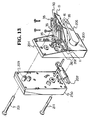
- the card reader is illustrated as a component of an electronic lock in Figure 13.
- the preferred electronic door lock with which the card reader according to the present invention can be used comprises a housing 200, outside lever 206, a lock operating mechanism 210, a latch bolt assembly 207, an inside housing 250 and inside lever (not shown).
- a strike box and strike plate (not shown) are mounted on the door jam in conventional manner.
- the card reader including the outside cover 10, spring 50, and electronic module 30, is located in the upper right of the housing 200 of the electronic lock.
- the card reader is secured to the lock by protrusions 11 and 12 and by a screw 201.
- Tabs 202 are positioned so that the protrusions 11 and 12 can rest against them and hold the card reader in a relatively horizontal position for servicing.
- the screw 201 is positioned so that access is from the inside of the door.
- the screw 201 fits through a hole 209 in the inside portion 250 of the electronic lock, through a hole 204 in the back plate of the housing 200 and secures the card reader by a threaded hole 16 when the outside cover is pivoted upward into position.
Landscapes
- Engineering & Computer Science (AREA)
- Physics & Mathematics (AREA)
- General Physics & Mathematics (AREA)
- Artificial Intelligence (AREA)
- Computer Vision & Pattern Recognition (AREA)
- Theoretical Computer Science (AREA)
- Lock And Its Accessories (AREA)
- Conveying Record Carriers (AREA)
- Push-Button Switches (AREA)
- Management, Administration, Business Operations System, And Electronic Commerce (AREA)
- Devices For Checking Fares Or Tickets At Control Points (AREA)
Applications Claiming Priority (2)
| Application Number | Priority Date | Filing Date | Title |
|---|---|---|---|
| US99929 | 1987-09-23 | ||
| US07/099,929 US4839508A (en) | 1987-09-23 | 1987-09-23 | Card reader |
Publications (2)
| Publication Number | Publication Date |
|---|---|
| EP0309193A2 true EP0309193A2 (de) | 1989-03-29 |
| EP0309193A3 EP0309193A3 (de) | 1989-11-29 |
Family
ID=22277282
Family Applications (1)
| Application Number | Title | Priority Date | Filing Date |
|---|---|---|---|
| EP88308691A Withdrawn EP0309193A3 (de) | 1987-09-23 | 1988-09-20 | Kartenleser |
Country Status (8)
| Country | Link |
|---|---|
| US (1) | US4839508A (de) |
| EP (1) | EP0309193A3 (de) |
| JP (1) | JPH01158584A (de) |
| KR (1) | KR890005633A (de) |
| CN (1) | CN1032250A (de) |
| AU (1) | AU598436B2 (de) |
| IL (1) | IL87752A0 (de) |
| TR (1) | TR23541A (de) |
Cited By (3)
| Publication number | Priority date | Publication date | Assignee | Title |
|---|---|---|---|---|
| FR2732396A1 (fr) * | 1995-04-03 | 1996-10-04 | Talleres Escoriaza Sa | Serrure electronique autonome a lecteur de proximite |
| FR2762698A1 (fr) * | 1997-04-24 | 1998-10-30 | Ascom Monetel Sa | Dispositif de protection d'une tete magnetique d'un lecteur de cartes |
| US11538035B2 (en) | 2005-09-15 | 2022-12-27 | Capital One Services, Llc | Wireless devices for storing a financial account card and methods for storing card data in a wireless device |
Families Citing this family (11)
| Publication number | Priority date | Publication date | Assignee | Title |
|---|---|---|---|---|
| JPH01269197A (ja) * | 1988-04-21 | 1989-10-26 | Tokyo Electric Co Ltd | 電子キャッシュレジスタ |
| DE3943703C2 (de) * | 1989-09-21 | 2001-06-21 | Amphenol Tuchel Elect | Chipkartenleser |
| US5168275A (en) * | 1990-02-07 | 1992-12-01 | International Business Machines Corporation | Method and apparatus for decoding two frequency (f/2f) data signals |
| EP0535632A3 (en) * | 1991-10-01 | 1993-05-19 | Japan Magnetic Lock Co., Ltd. | Burglarproof system for automotive vehicle |
| US5466920A (en) * | 1991-11-08 | 1995-11-14 | Microbilt Corporation | Real time decoding for card transaction terminal |
| US5369263A (en) * | 1992-10-30 | 1994-11-29 | Microbilt Corporation | Embossed card reader |
| AU5538494A (en) * | 1992-10-30 | 1994-05-24 | Microbilt Corporation | Multi-reader transaction terminal |
| US5834756A (en) * | 1996-06-03 | 1998-11-10 | Motorola, Inc. | Magnetically communicative card |
| JP2003099903A (ja) * | 2001-09-26 | 2003-04-04 | Sankyo Seiki Mfg Co Ltd | 手動式磁気カードリーダおよび磁気データ読取方法 |
| US20060093506A1 (en) * | 2004-11-03 | 2006-05-04 | Lg Electronics Inc. | Scroll compressor |
| US9754136B2 (en) | 2014-10-28 | 2017-09-05 | Poynt Co. | Low-profile card reader |
Family Cites Families (11)
| Publication number | Priority date | Publication date | Assignee | Title |
|---|---|---|---|---|
| US29846A (en) * | 1860-08-28 | kittle | ||
| US3622991A (en) * | 1969-09-16 | 1971-11-23 | Electro Optics Devices Corp | Electronic locking system |
| US3705396A (en) * | 1970-06-05 | 1972-12-05 | Sony Corp | Drive mechanism for use with information cards |
| US3836753A (en) * | 1971-12-05 | 1974-09-17 | Amp Inc | Magnetic card reader |
| US3896293A (en) * | 1973-08-06 | 1975-07-22 | Amp Inc | Card reader transport mechanism |
| US3926021A (en) | 1974-01-02 | 1975-12-16 | Monitron Ind | Electronic combination lock and system |
| US4126780A (en) * | 1976-09-17 | 1978-11-21 | Decicom Systems, Inc. | On the fly optical card reader |
| US4322613A (en) * | 1980-04-08 | 1982-03-30 | Vendacopy, Inc. | Method for tamper-proofing magnetic stripe card reader |
| US4375071A (en) * | 1980-10-20 | 1983-02-22 | Amp Incorporated | Mounting means for magnetic read head |
| US4519228A (en) * | 1981-04-01 | 1985-05-28 | Trioving A/S | Electronic recodeable lock |
| JPS589262A (ja) * | 1981-07-08 | 1983-01-19 | Nippon Denso Co Ltd | 磁気カ−ド読取装置 |
-
1987
- 1987-09-23 US US07/099,929 patent/US4839508A/en not_active Expired - Fee Related
-
1988
- 1988-09-15 IL IL87752A patent/IL87752A0/xx unknown
- 1988-09-20 EP EP88308691A patent/EP0309193A3/de not_active Withdrawn
- 1988-09-21 AU AU22456/88A patent/AU598436B2/en not_active Ceased
- 1988-09-22 KR KR1019880012247A patent/KR890005633A/ko not_active Withdrawn
- 1988-09-22 JP JP63238674A patent/JPH01158584A/ja active Pending
- 1988-09-23 CN CN88106861A patent/CN1032250A/zh active Pending
- 1988-09-23 TR TR744/88A patent/TR23541A/xx unknown
Cited By (3)
| Publication number | Priority date | Publication date | Assignee | Title |
|---|---|---|---|---|
| FR2732396A1 (fr) * | 1995-04-03 | 1996-10-04 | Talleres Escoriaza Sa | Serrure electronique autonome a lecteur de proximite |
| FR2762698A1 (fr) * | 1997-04-24 | 1998-10-30 | Ascom Monetel Sa | Dispositif de protection d'une tete magnetique d'un lecteur de cartes |
| US11538035B2 (en) | 2005-09-15 | 2022-12-27 | Capital One Services, Llc | Wireless devices for storing a financial account card and methods for storing card data in a wireless device |
Also Published As
| Publication number | Publication date |
|---|---|
| IL87752A0 (en) | 1989-02-28 |
| EP0309193A3 (de) | 1989-11-29 |
| AU598436B2 (en) | 1990-06-21 |
| TR23541A (tr) | 1990-03-22 |
| CN1032250A (zh) | 1989-04-05 |
| KR890005633A (ko) | 1989-05-16 |
| AU2245688A (en) | 1989-03-23 |
| US4839508A (en) | 1989-06-13 |
| JPH01158584A (ja) | 1989-06-21 |
Similar Documents
| Publication | Publication Date | Title |
|---|---|---|
| US4839508A (en) | Card reader | |
| US5780827A (en) | Landing contact mechanism and card latch for smart card reader/writer | |
| US4466680A (en) | Electrical connecting device | |
| US5339662A (en) | Door locking system | |
| US7172463B2 (en) | Adapter device | |
| US20050033992A1 (en) | Input device | |
| US4475222A (en) | Tape cassette with use counter | |
| US12349294B2 (en) | Terminal apparatus assembly and terminal equipment including same | |
| US4585930A (en) | Slotless magnetic card reader | |
| US6367700B1 (en) | IC card reader | |
| US4902882A (en) | Code reader | |
| EP0351089B1 (de) | Auswischmechanismus für Kartenabtaster | |
| GB2299613A (en) | A self contained electronic lock with proximity reader | |
| US6869017B2 (en) | Card connector | |
| JP3994410B2 (ja) | 人に関連して走行データを検出するために使用される車両用のチップカードのための収容装置 | |
| US4614862A (en) | Electrically actuatable locking device | |
| US4831388A (en) | Elapsed time recorder | |
| US4423317A (en) | Micro card reader | |
| JP4950253B2 (ja) | 鍵管理システム | |
| CA1154531A (en) | Record side identification apparatus for video disc player | |
| JP3341140B2 (ja) | Icカード処理装置 | |
| US8783569B2 (en) | Card processing device | |
| US4423320A (en) | Encoded card reader | |
| JP2555321Y2 (ja) | カード錠装置 | |
| US4480180A (en) | Cartridge assembly for data-sensing system |
Legal Events
| Date | Code | Title | Description |
|---|---|---|---|
| PUAI | Public reference made under article 153(3) epc to a published international application that has entered the european phase |
Free format text: ORIGINAL CODE: 0009012 |
|
| AK | Designated contracting states |
Kind code of ref document: A2 Designated state(s): BE CH DE ES FR GB IT LI NL |
|
| PUAL | Search report despatched |
Free format text: ORIGINAL CODE: 0009013 |
|
| AK | Designated contracting states |
Kind code of ref document: A3 Designated state(s): BE CH DE ES FR GB IT LI NL |
|
| RAP1 | Party data changed (applicant data changed or rights of an application transferred) |
Owner name: EMHART INDUSTRIES, INC. |
|
| 17P | Request for examination filed |
Effective date: 19900425 |
|
| 17Q | First examination report despatched |
Effective date: 19911031 |
|
| STAA | Information on the status of an ep patent application or granted ep patent |
Free format text: STATUS: THE APPLICATION IS DEEMED TO BE WITHDRAWN |
|
| 18D | Application deemed to be withdrawn |
Effective date: 19920311 |