EP0309205A1 - Déflecteur optique placé derrière un objectif - Google Patents
Déflecteur optique placé derrière un objectif Download PDFInfo
- Publication number
- EP0309205A1 EP0309205A1 EP88308717A EP88308717A EP0309205A1 EP 0309205 A1 EP0309205 A1 EP 0309205A1 EP 88308717 A EP88308717 A EP 88308717A EP 88308717 A EP88308717 A EP 88308717A EP 0309205 A1 EP0309205 A1 EP 0309205A1
- Authority
- EP
- European Patent Office
- Prior art keywords
- optical deflector
- postobjective
- polygonal
- curved surface
- axis
- Prior art date
- Legal status (The legal status is an assumption and is not a legal conclusion. Google has not performed a legal analysis and makes no representation as to the accuracy of the status listed.)
- Granted
Links
Images


Classifications
-
- G—PHYSICS
- G02—OPTICS
- G02B—OPTICAL ELEMENTS, SYSTEMS OR APPARATUS
- G02B26/00—Optical devices or arrangements for the control of light using movable or deformable optical elements
- G02B26/08—Optical devices or arrangements for the control of light using movable or deformable optical elements for controlling the direction of light
-
- G—PHYSICS
- G02—OPTICS
- G02B—OPTICAL ELEMENTS, SYSTEMS OR APPARATUS
- G02B5/00—Optical elements other than lenses
- G02B5/08—Mirrors
- G02B5/09—Multifaceted or polygonal mirrors, e.g. polygonal scanning mirrors; Fresnel mirrors
-
- G—PHYSICS
- G02—OPTICS
- G02B—OPTICAL ELEMENTS, SYSTEMS OR APPARATUS
- G02B26/00—Optical devices or arrangements for the control of light using movable or deformable optical elements
- G02B26/08—Optical devices or arrangements for the control of light using movable or deformable optical elements for controlling the direction of light
- G02B26/10—Scanning systems
Definitions
- the present invention relates to a postobjective optical deflector employing a polygonal mirror.
- the conventional laser printer or the like employs a postobjective optical optical scanner in which light beams fall on an optical deflector after being converged by a converging lens or a preobjective optical scanner in which light beams passes a converging lens after being deflected by an optical deflector.
- the preobjective optical scanner is used generally because the preprojective optical scanner is capable of easily correcting the curvature of image surface and f8 characteristics by a converging lens and capable of converging light beams on a plane.
- the converging lens must be a wide-angle lens capable of coveging an angle of deflection, the preobjective optical scanner needs an expensive converging lens having a complex construction. Accordingly, the postobjective optical scanner is employed when a converging lens having a simple construction must be used.
- the postobjective optical scanner employs a converging lens having a simple construction
- the point of convergence in general, is on a curved surface. Accordingly. the curvature of image must be corrected when the postobjective optical scanner is employed.
- Japanese Patent Laid-open (Kokai) No. 61-156020 discloses an postobjective optical scanner employing a polygonal mirror having a spherical or cylindrical reflecting surface to reduce the curvature of image surface.
- This postobjective optical scanner reduces the curvature of image surface to a practically negligible extent.
- the post objective optical scanner is unable to correct scanning nonlinearity and needs electrical means for correcting scanning nonlinearity.
- a clock is vaned continuously or stepwise to correct scanning nonlinearity.
- a postobjective optical deflector comprises: a polygonal deflector having convex curved or cylindrical reflecting surfaces for reflecting light emitted from a light source: and a correcting lens disposed between the polygonal deflector and an objective surface and having a cylindrical surface having power on the feed side or a rotationally symmetric surface having an axis of rotational symmetry parallel to the scanning direction, and a curved surface of an even degree having power on the scanning side.
- the curvature of image surface can be corrected owing to the variation of the power of the reflecting surfaces according to the angle of deflection of light beams.
- the flat surface of a general cylindrical lens is replaced with a curved surface having power on the scanning side, and the other surface of the cylindrical lens is formed in a cylindrical surface or a rotationally symmetric surface having an axis of rotational symmetry parallel to the scanning direction depending on the required degree of accuracy of correction.
- the tilt of the polygonal deflector, as well as the curvature of image surface and fa characteristics, can be corrected, therefore, the combination of the polygonal deflector and the correcting lens achieves highly accurate correction of the curvature of image surface and fe characteristics.
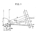
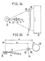
- a postobjective optical deflector in a first embodiment according to the present invention comprises a polygonal optical deflector 1, and a correcting lens 3 disposed near an objective surface 2.
- the polygonal optical deflector 1 rotates about an axis passing a point 0, and has six reflecting surfaces 4 each being a portion of an elliptic cylinder having its center at a point O 1 , a major axis of b in length, and a minor axis of c in length.
- the correcting lens 3 has a cylindrical surface 5, which is similar to the cylindrical surface of an cylindrical lens, and a curved surface 6 of higher degree expressed by 1 x 10- 2 X 2 - 4 x 10- 3 xl. That is, the curved surface 6 is a curved surface of an even degree.
- An axial light beam 7 and a differential light beam 8 fall on the reflecting surface 4 of the polygonal optical deflector 1 so as to converge on a point S c at a distance t from the center 0 of the polygonal optical deflector 1.
- the axial light beam 7 and the differential light beam 8 reflected by the reflecting surface 4 of the polygonal optical deflector 1 travel through the correcting lens 3 and are focused on a point S.
- the polygonal optical deflector 1 has the axis of rotation passing the center O perpendicularly to a plane swept by a scanning beam.
- Rm is the radius of the inscribed circle of the polygonal optical deflector 1
- R is the distance between the center 0 and the objective surface 2
- Lo is an effective scanning distance
- 9 is the phase of the polygonal optical deflector 1
- y is the position of a scanning spot on the objective surface 2.
- the phase 8 ec.
- the polygonal optical deflector turns through an angle of 60 for one scanning cycle.
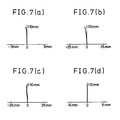
- the parameters namely, the distance R, the coefficients of x to the second power and x to the fourth power of the function defining the curved surface of higher degree forming the curved surface 6, the thickness of the correcting lens 3, and the position of the correcting lens 3, were varied properly to optimize the curvature of. scanning line, the curvature of image surface in the scanning direction, the curvature of image surface in the feed direction and fe characteristics. Examples and measured results will be described hereinafter.
- the maximum curvature of scanning line was -6.425 ⁇ m
- the maximum dislocation of image surface in the feed direction was -0.9797 mm
- the maximum dislocation of image surface in the scanning direction was -3.936 mm
- the maximum f ⁇ error was -0.2996 mm.
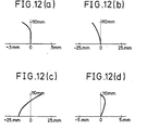
- Results simulation are shown in Figs. 10(a) (curvature of scanning line), 10(b) (curvature of image surface in the feed direction), 10(c) (curvature of image surface in the scanning direction), and 10(d) (fe error).
- the maximum curvature of scanning lines was -0.1452 mm
- the maximum dislocation of image surface in the feed direction was -5.048 mm
- the maximum dislocation of image surface in the scanning direction was 1.823 mm
- the maximum fe error was 0.4364 mm.
- Figs. 11 (a) (curvature of scanning line), 11 (b) (curvature of image surface in the feed direction), 11(c) (curvature of image surface in the scanning direction) and 11(d) (fe error).
- the maximum curvature of scanning line was -0.1855 mm
- the maximum dislocation of image surface in the feed direction was -9.3695 mm
- the maximum dislocation of image surface in the scanning direction was. -3.7739 mm.
- the maximum f ⁇ error was 0.3842 mm.
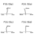
- Results simulation are shown in Figs. 13(a) (curvature of scanning line), 13(b) (curvature of image surface in the feed direction), 13(c) (curvature of image surface in the scanning direction), and 13(d) (fe error).
- the maximum curvature of scanning line was 0.1038 mm
- the maximum dislocation of image surface in the feed direction was -6.9492 mm
- the maximum dislocation of image surface in the scanning direction was 3.2086 mm
- the maximum fe error was -0.0655 mm.
- each reflecting surfaces of the polygonal optical deflector has two axial components and hence have degree of freedom greater by one than that of spherical or cylindrical reflecting surfaces.
- the degree of freedom of design is increased. Since one of the surfaces of the correcting lens employed in the polyonal optical deflector of the present invention corresponding to the flat surface of the ordinary cylindrical correcting lens is formed in a curved surface of even degree, the tilt of the reflecting surfaces of the polygonal optical deflector can be corrected, and thereby the combination of the polygonal optical deflector and the pseudocylindrical correcting lens corrects the curvature of image surface and f ⁇ characteristics at a high accuracy.
- a postobjective optical deflector in a second embodiment according to the present invention comprises a polygonal optical deflector 1. and a pseudocylindncal correcting lens 3 disposed near an objective surface 2.
- the polygonal optical deflector 1 rotates about an axis passing a point (center) 0 perpendicular to the sheet.
- the pseudocylindrical correcting lens 3 has a cylindrical surface 5 similar to that of the ordinary cylindrical lens, and a curved surface 6 of higher degree having a contour defined by a 2 x 2 + a L x 4 (a 2 and a4 are coefficients)
- the axial beam 7 and the differential beam 8 reflected by the reflecting surface 4 are focused by the pseudocylindrical correcting lens 3 on a point S.
- Rm is the radius of the inscribed circle of the circumferential contour of the polygonal optical deflector 1
- R is the distance between the axis of rotation of the polygonal optical deflector 1 and the objective surface 2
- Lo not shown, is the effective scanning distance
- 0 is the phase of the polygonal optical deflector 1
- y is the position of a scanning spot on the objective surface 2.
- the rotation of the polygonal optical deflector 1 through an angle of 60° corresponds to one scanning cycle.
- Simulated operation of examples of the second embodiment was performed to determined optimum values for the parameters including the distance R, the coefficient a 2 of x to the second power, the coefficient a 4 of x to the fourth power, the thickness of the pseudocylindrical correcting lens 3 and the disposition of the pseudocylindrical correcting lens 3 so that the curvature of image surface in the feed direction, the curvature of image surface in the scanning direction, the curvature of scanning line and the f 9 characteristics are corrected appropriately.
- Figs. 17 and 18 show light beams in this example, as viewed in the z-axis and the x-axis, respectively.
- the paths of the light beams are similar to those shown in Figs. 17 and 18.
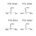
- Figs. 20(a) curvevature of scanning line
- 20(b) curvevature of image surface in the feed direction
- 29(c) curvature of image surface in the scanning direction
- 20(d) f ⁇ error
- the maximum curvature of scanning line was 3.7581 x 10- 2 mm
- the maximum curvature of image in the feed direction was -5.9444 mm
- the maximum curvature of image surface in the scanning direction was-2.1230 mm
- the maximum fe error was -2.3171 x 10- 2 mm.
- the postobjective optical deflector in the second embodiment comprises the polygonal optical deflector having the reflecting surfaces each formed of a portion of a convex hyperboloid or a convex hyperbolic cylinder, and the pseudocylindrical correcting lens disposed between the polygonal optical deflector and the objective surface, and having a cylindrical surface having its power on the feed side, and a curved surface of an even degree having its power on the scanning side. Since each reflecting surface of the polygonal optical deflector has two axial components, the degree of freedom of the reflecting surface is greater by one than that of a reflecting surface formed of a portion of spherical surface or a cylindrical surface, which increases the degree of freedom of design.
- the surface of the correcting lens employed in the second embodiment corresponding to the flat surface of the ordinary correcting lens is formed of a curved surface of even degree, the tilt of the reflecting surfaces of the polygonal optical deflector and the curvature of image surface can be corrected and the fe characteristics can be improved.
- the combination of the polygonal optical deflector and the pseudocylindrical correcting lens corrects the curvature of image surface and fe characteristics at a high accuracy.
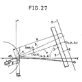
- a postobjective optical deflector in a third embodiment according to the present invention comprises a polygonal optical deflector 1, and a pseudoicylindrical correcting lens 3 disposed near to objective surface 2.
- the polygonal optical deflector 1 rotates about an axis passing a point (center) 0 and perpendicular to a plane swept by a scanning beam, and has six reflecting surface 4 each formed of a portion of a paraboloid or a parabolic cylinder.
- the pseudocylindrical correcting lens 3 has a cylindrical surface 5 similar to that of the ordinary cylindrical lens, and a curved surface 6 of higher degree having a contour represented by: a2x2 + a4x 4 (a 2 and a 4 are constants). That is, the curved surface 6 is a curved surface of even degree.
- An axial light beam 7 and a differential light beam 8 fall on the reflecting surface 4 of the polygonal optical deflector 1 so as to converge on a point So at a distance t from the center 0 of the polygonal optical deflector 1.
- the axial light beam and the differential light beam 8 reflected by the reflecting surface 4 of the polygonal optical deflector 1 travel through the correcting lens 3 and are focused on a point S.
- a is the coefficient of x of the second degree
- Rm is the radius of the inscribed circle of the circumferential contour of the polygonal optical deflector 1
- R is the distance between the axis of rotation of the polygonal optical deflector 1 and the objective surface 2
- an effective scanning distance L o is the effective scanning distance, not shown
- P is the phase of the polygonal optical deflector 1
- y is the position of a scanning spot on the objective surface 2.
- the polygonal optical deflector 1 turns through an angle of 60° for one scanning cycle.
- Parametric simulation was performed to determine the parameters, namely, the coefficient a of second degree of the parabolic surface or parabolic cylinder forming the reflecting surfaces of the polygonal optical deflector 1, the distance R, the coefficients of x to the second power and fourth power of the equation defining the curved 6 of higher degree of the pseudocylindrical correcting lens 3, the thickness of the pseudocylindrical correcting lens 3, and the disposition of the pseudocylindrical correcting lens, to reduce the error in the linearity of the scanning line to zero.
- Results of parametric simulation were evaluated in terms of curvature of image surface in the feed direction, curvature of image surface in the scanning direction, f ⁇ characteristics and curvature of scanning line
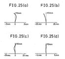
- Figs. 23 (light beams as viewed along the x-axis), 24 (light beams as viewed along the z-axis), 25(a) (curvature of scanning line), 25(b) (curvature of image surface in the feed direction), 25(c) (curvature of image surface in the scanning direction), and 25(d) (f ⁇ error).
- the maximum curvature of scanning line was -6.2888 x 10- 2 mm
- the maximum curvature of image surface in the feed direction was -6.6502 mm
- the maximum curvature of image surface in the scanning direction was -2.26410
- the maximum f ⁇ error was -0.1884 mm.
- Paths of light beams as viewed along the z-axis and the x-axis are similar to those shown in Figs. 23 and 24.
- the postobjective optical deflector in the third embodiment according to the present invention thus comprises the polygonal optical deflector having reflecting surfaces for reflecting a light beam emitted from a light source each formed of a portion of a convex parabolic surface of a parabolic cylinder, and the pseudocylindrical correcting lens disposed between the poylgonal optical deflector and the objective surface, and having a cylindrical surface having power on the feed side, and a curved surface of even degree having power on the scanning side, the f ⁇ characteristics and curvature of image surface can be corrected by the variation in the curvature of the reflecting surfaces of the polygonal optical deflector each formed of a portion of a parabolic surface of a parabolic cylinder and by the power in the scanning direction of the cylindrical surface of the pseudocylindrical correcting lens.
- the combination of the polygonal optical deflector and the pseudocylindrical correcting lens correct the curvature of image surface and f 6 characteristics at a high accuracy.
- a postobjective optical deflector in a fourth embodiment according to the present invention comprises a polygonal optical deflector 1 and a pseudocylindrical correcting lens 3 disposed near an objective surface 2.
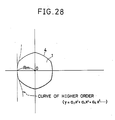
- the polygonal optical deflector 1 rotates about an axis passing a point (center) 0 perpendicularly to a plane swept by a scanning beam, and has six reflecting surfaces 4 each formed of a curved surface of a higher degree not less than fourth degree defined by a polynominal of even degree.
- the pseudocylindrical correcting lens 3 has a cylindrical surface similar to that of the ordinary cylindrical lens and a curved surface 6 of higher degree defined by a 2 x 2 + a4x 4 (a2 and a4 are constants). That is, the curved surface 6 is a curved surface of even degree.
- An axial light beam 7 and a differential light beam 8 fall on the reflecting surface 4 of the polygonal optical deflector 1 so as to converge on a point So at a distance t from the center 0 of the polygonal optical deflector 1.
- the axial light beam 7 and the differential light beam 8 reflected by the reflecting surface 4 of the polygonal optical deflector 1 travel through the pseudocylindrical correcting lens 3 and are focused on a point S.
- Coefficients a 2 , a4 and a 6 are the coefficient respectively of a term of the second degree, a term of the fourth degree and a term of the sixth degree of the polynominal of even degree defining the shape of the polygonal optical reflecting surfaces 4,
- Rm is the radius of an inscribed circle of the circumferential contour of the polygonal optical deflector 1
- R is the distance between the axis of rotation of the polygonal optical deflector 1 and the objective surface 2
- L o is an effective scanning distance, not shown
- 8 is the phase of the polygonal optical deflector 1.
- the polygonal deflector 1 turns through an angle of 60° for one scanning cycle.
- Parametric simulation was performed to determine the coefficients a 2 , a 4 and a 6 , the distance R, the coefficients of x to the second power and the fourth power of an expression representing the curved surface 6 of higher degree of the pseudocylindrical correcting lens 3, the thickness and disposition of the pseudocylindrical correcting lens 3 so that the effective scanning distance is 220 mm when the available angular range of reflecting surface is an angle of 40° and error in the linearity of the scanning line is reduced to zero.
- Results of simulation were evaluated in terms of curvature of scanning line, curvature of image surface in the feed direction, curvature of image surface in the scanning direction, and f6 characteristics.
- Figs. 29 and 30 show light beams as viewed along the z-axis and the x-axis, respectively.
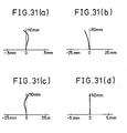
- Figs. 31 (a) (curvature of scanning line), 31 (b) (curvature of image surface in the feed direction), 31 (c) (curvature of image surface in the scanning direction), and 31 (d) (fe error).
- the maximum curvature of scanning line was 6.2161 x 10- 2 mm
- the maximum curvature of image surface in the feed direction was -6.5394 mm
- the maximum curvature of image surface in the scanning direction was -2.6151 mm
- the maximum f ⁇ was -5.7676 x 10- 2 mm.
- Paths of light beams as viewed along the z-axis and along the x-axis are similar to those shown in Figs. 29 and 30.
- Figs. 32(a) curvevature of scanning line
- 32(b) curvevature of image surface in the feed direction
- 32(c) curvevature of image surface in the scanning direction
- 32(d) f8 error
- the maximum curvature of scanning lines was 4.2962 x 10- 2 mm
- the maximum curvature of image surface in the feed direction was -4.4578 mm
- the maximum curvature of image surface in the scanning direction was 0.7152 mm
- the maxmum f 8 error was -7.0998 x 10- 3 mm.
- the postobjective optical deflector in the fourth embodiment comprises the polygonal optical deflector having convex, curved reflecting surfaces each formed of a portion of a curved surface of higher degree represented by a polynominal of even degree not less than fourth degree, and the pseudocylindrical correcting lens disposed between the polygonal optical deflector and the objective surface and having a cylindrical surface having its power on the feed side and a curved surface of even degree having its power on the scanning side. Accordingly, the postobjective optical deflector in the fourth embodiment according to the present invention has degree of freedom of design greater than that employing a correcting lens having spherical or cylindrical surfaces.
- the surface of the pseudocylindrical correcting lens corresponding to the flat surface of the ordinary cylindrical correcting lens is formed of a portion of a curved surface of even degree, the tilt of the polygonal optical deflector can be corrected, and the curvature of image surface and fe characteristics can be improved.
- the combination of the polygonal optical deflector and the pseudocylindrical correcting lens of the present invention achieves the correction of curvature of image surface and fe characteristics at a high accuracy.
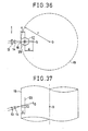
- a semiconductor laser 11 serving as a light source
- a collimating lens 12 to collimate light beams emitted from the semiconductor laser 11
- a cylindrical lens 13 and a converging lens 14.
- a polygonal optical deflector 17 (polygonal rotating mirror) having a plurality of reflecting surfaces 16 is disposed on the optical path and is mounted fixedly on the output shaft of a motor 15.
- Each reflecting surface 16 is formed of a portion of a spherical surface or a cylindrical surface having its power (power is the refractive power or focusing power of an optical surface) in scanning directions indicated by a double-head arrow.
- a correcting lens 20 covering the angular range of a light beam reflected by the polygonal optical deflector 17 is disposed near an objective surface 21 of a cylindrical photosensitive drum 22. Light beams travel through the correcting lens 20 and fall on the objective surface 21 of the photosensitive drum 22.
- the correcting lens 20 has a surface 25 of incidence forming one of the surfaces thereof and having its power in both the scanning direction and the feed direction perpendicular to the scanning direction, namely, a rotationally symmetric surface 24 formed of a portion of a rotationally symmetric surface and having an axis 23 of rotational symmetry extending in parallel to the scanning direction, and a surface 26 of departure forming the other surface thereof, having its power in the scanning direction and symmetric with respect to an axis perpendicular to the scanning direction.
- the surface 26 of departure is a rotationally symmetric curved surface 28 having an axis 27 of rotational symmetry passing the centre 0 2 of a laterally symmetric shape with respect to the scanning direction and perpendicular to the axis 23 of rotational symmetry of the surface 25 of incidence.
- the distance between the circumference of the photosensitive drum 22 and the axis 29 of rotation of the polygonal optical deflector 17 is A
- the distance between the axis 29 of rotation of the polygonal optical deflector 17 and the surface 25 of incidence of the correcting lens 20 is B.
- Light beams emitted from the semiconductor laser 11 in response to a print signal are collimated in parallel light beams by the collimating lens 12, travel through the cylindrical lens 13 having its power in the feed direction, and the converging lens 14, and then fall on the reflecting surface 16 of the polygonal optical deflector 17.
- the spot of the parallel light beams passed through the correcting lens 20 moves on the objective surface 21 of the photosensitive drum 22 in the scanning direction for recording.
- Each reflecting surface 16 of the polygonal optical deflector 17 is formed of a portion of a cylindrical surface having a circular cross section indicated by a broken line with a radius r and with its center at a point O.
- the axis 29 of rotation of the polygonal optical deflector 17 is parallel to the axis of the cylindrical surface passing the point 0.
- the cylindrical lens 13 and the converging lens 14 are disposed so that light beams converge on a point S when the light beams are projected in the direction of the axis 29 of rc-ation, and so that the light beams converge on the reflecting surface 16 when the light beams are projected in the scanning direction.
- the distance between the axis 29 of rotation of the polygonal optical deflector 17 and the point S is d.
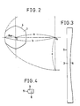
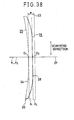
- the morphology of the correcting lens 20 will be described with reference to Fig. 38 showing the correcting lens 20 in a section taken on a plane parallel to the scanning direction.
- the surface 25 of incidence is formed of a portion of a rotationally symmetric surface 24 having an axis 23 of rotational symmetry.
- the radius of the surface 25 of incidence at the center 0, therefore is e.
- the contour of the section of the surface 25 of incidence is expressed by a polynominal of degree eight:
- the surface 26 of departure is symmetric with respect to the Yi -axis and is formed of a portion of a rotationally symmetric surface 28 having an axis 27 of rotational symmetry coinciding with the Yi -axis.
- the contour of the section of the surface 26 of departure is expressed by a polynominal of degree eight:
- the correcting lens 20 is formed of an acrylic resin having a refractive index of 1.48.
- the coefficients of the equations (1) and (2) will be described afterward.
- the scanning line on the photosensitive drum 22 is liable to curve particularly in a skew incidence optical system in which light beams fall on the reflecting surface 16 of the polygonal optical deflector 17 at an angle e to a plane perpendicular to the axis 29 of rotation of the polygonal optical deflector 17.
- the effective scanning distance was 220 mm and the corresponding available angular range of the reflecting surface 16 of the polygonal optical deflector 17 was 36°.
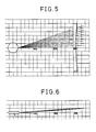
- Fig. 39 The curvature of scanning line, the curvature of meridional image surface, the curvature of sagittal image surface and fe obtained through the computer simulation are shown in Fig. 39.
- the vertical axes extend along the scanning direction, and the characteristics are measured on the horizontal axes.
- the phase of the polygonal optical deflector 17 is zero when the polygonal optical deflector 17 is in a position as shown in Fig. 36.
- the effective scanning distance was 220 mm and the corresponding available angular range of the reflecting surface 16 of the polygonal optical deflector 17 was 36°.
- Table 1 Tabulated in Table 1 are the curvature of the sagittal image surface, curvature of meridional image surface, linearity of fe characteristics and curvature of scanning line of the Examples 1 and 2 of the fifth embodiment of the present invention and the example of a postobjective optical deflector employed in a known optical scanning device disclosed in Japanese Patent Laid-open (Kokai) No. 61-156020, obtained through computer simulation.
- simulation Nos. 1, 2 and 3 are for Examples 1, 2 and 3 of the known postobjective optical deflector, respectively, and simulation Nos. 4 and 5 are for the Examples 1 and 2 of the fifth embodiment of the present invention, respectively.
- simulation Nos. 4 and 5 the linearity is presented by the maximum value at a scanning speed in the middle portion of the scanning line.
- the curvature of sagittal image surface and the curvature of meridional image surface in the fifth embodiment of the present invention are approximately 1/2, and 1/4 to 1/5 respectively of those of the example of the known postobjective optical deflector.
- values for the fifth embodiment of the present invention are not more than 2 to 3%, which needs no additional correcting means such as electrical correcting means.
- the fifth embodiment is capable of correcting the curvature of scanning line to a practically negligible extent.
- the postobjective optical deflector may be provided with a plurality of correcting lenses in view of various manufacturing conditions.
- the correcting lens 20 may be substituted by two lenses, namely, a first lens having the same surface of incidence as that of the correcting lens 20, and a spherical surface of departure, and a second lens having a spherical surface of incidence, and the same surface of departure as that of the correcting lens 20.
- the postobjective optical deflector in the fifth embodiment according to the present invention comprises: the polygonal optical deflector having a plurality of reflecting surfaces each formed of a portion of a spherical surface or a cylindrical surface having its power in the scanning direction; and the correcting lens disposed between the polygonal optical deflector and the objective surface, having a rotationally symmetric curved surface of incidence having a cross section having the shape of an arc of a circle with its center on the axis of rotational symmetry, rotationally symmetric with respect to a plane including the axis of rotation of the polygonal optical deflector and perpendicular to the axis of rotational symmetry and having its power in both the scanning direction and the feed direction, and a surface of departure symmetrical with respect to a plane perpendicular to the scanning direction and having its power in the scanning direction.
- the curvature of image surface in the scanning direction namely, a sagittal image surface
- the curvature of image surface in the scanning direction can be corrected by forming each reflecting surface of a polygonal optical deflector by a portion of a spherical surface of a cylindrical surface having its power in the scanning direction.
- the surface of incidence of the correcting lens is formed of a rotationally symmetric curved surface rotationally symmetric with respect to an axis of symmetry parallel to the scanning direction, the power in the feed direction can be varied by varying the curvature of the surface of incidence with respect to the feed direction along the scanning direction, and thereby the curvature of the image surface in the feed direction, namely, the meridional image surface, can be corrected.
- forming the surface of departure of the correcting lens in a curved surface having its power in the scanning direction enables the correction of fe characteristics and the further accurate correction of the sagittal image surface.
- the curvature of the sagittal image surface, the curvature of the meridional image surface and fe characteristics can be corrected by the combined correcting effects of the reflecting surfaces of the polygonal optical deflector, and the surfaces of incidence and departure of the correcting lens. Furthermore, the correction of fe characteristics, which has been a significant problem, can be achieved by optical means without requiring any electrical means, so that the postobjective optical deflector of the present invention has high performance, and is simple in construction and inexpensive.
- a semiconductor laser 31 serving as a light source
- a collimating lens 32 to collimate light beams a cylindrical lens 33
- a converging lens 34 arranged on the same optical path.
- a polygonal optical deflector (polygonal rotating mirror) 37 having a plurality of reflecting surfaces 36 is disposed on the optical path and is mounted fixedly on the output shaft of a motor 35.
- Each reflecting surface 36 is a curved surface 38 varying in curvature from position to position thereon.
- a correcting lens 39 is disposed so as to cover the angular range of light beams reflected by the polygonal optical deflector 37, and a cylindrical photosensitive drum 41 having an objective surface 40 on which light beams transmitted through the correcting lens 39 fall is disposed behind the correcting lens 39.
- the correcting lens 39 has its power (refractive power or focusing power) in both the scanning direction indicated by a double-head arrow and the feed direction perpendicular to the scanning direction.
- the correcting lens 39 has a surface 44 of incidence formed of a portion of a rotationally symmetric curved surface 43 having an axis 44 of symmetry parallel to the scanning direction, and a surface 45 of departure having its power in the scanning direction and symmetric with respect to an axis perpendicular to the scanning direction.
- the surface 45 of departure is formed of a portion of a rotationally symmetric curved surface 47 having an axis 46 of rotational symmetry passing the center 0 2 of a laterally symmetric shape with respect to the scanning direction and perpendicular to the axis 42 of rotational symmetry of the surface 44 of incidence.
- the distance between the objective surface 40 and the axis 48 of rotation of the polygonal optical deflector 37 is A
- the distance between the axis 48 of rotation of the polygonal optical deflector 37 and the surface 44 of incidence of the correcting lens 39 is B.
- Light beams emitted from the semiconductor laser 31 in response to a print signal are collimated in parallel light beams by the collimating lens 32, travel through the cylindrical lens 33 having its power in the feed direction, and the converging lens 34, and then fall on the reflecting surface 36 of the polygonal optical deflector 37.
- the spot of the parallel light beams passed through the correcting lens 39 moves on the objective surface 40 of the photosensitive drum 41 in the scanning direction for recording.
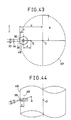
- the optical geometry of the polygonal optical deflector 37 having the reflecting surface 36 each formed of a portion of an elliptic cylinder having an elliptic contour 49, the cylindrical lens 33 and the converging lens 14 will be described hereinafter with reference to Figs. 43 and 44.
- the elliptic contour 49 has its center at a point 0, a minor axis of a in length, and a major axis of b in length.
- Each reflecting surface 36 of the polygonal optical deflector 37 is formed of a portion corresponding to the minor axis of a in length of the elliptic cylinder.
- the cylindrical lens 33 and the converging lens 34 are disposed so that light beams converge on a point S when the light beams are projected in the direction of the axis 48 of the polygonal optical deflector 37, and so that the light beams converge on the reflecting surface 36 of the polygonal optical deflector 37 when the light beams'are projected in the scanning direction.
- the distance between the axis 48 of rotation of the polygonal optical deflector 37 and the point S is d.
- Fig. 45 showing the correcting lens 39 in a cross section taken on a plane parallel to the scanning direction
- the surface 44 of incidence is formed of a portion of a rotationally symmetric curved surface 43 having an axis 42 of rotational symmetry.
- the radius of the rotationally symmetric curved surface at the center O 1 is e.
- the contour of the surface 44 of incidence 44 is expressed by a polynominal of degree eight:
- the surface 45 of departure is symmetric with respect to the Y 1 -axis and is formed of a portion of a rotationally symmetric surface 47 having an axis 46 of rotational symmetry coinciding with the Y 1 -axis.
- a coordinate system having an origin on a center Oz, an Xz-axis extending in parallel to the scanning direction, and a Y 2 -axis coinciding with the Y 1 -axis
- the contour of the central section of the surface 44 of incidence is expressed by a polynominal of degree eight:
- the correcting lens 39 is formed of an acrylic resin having a refractive index of 1.48.
- the coefficients of the equations (4) and (5) will be described afterward.
- Computer simulation was performed to determine the parameters so that the f8 characteristics, th curvature of a sagittal image surface, the curvature of a meridional image surface and the curvature of scanning line on the photosensitive drum 41 can be corrected to a practically negligible extent.
- the scanning line on the photosensitive drum 41 is liable to curve particularly in a skew incidence optical system in which light beams fall on the reflecting surface 36 of the polygonal optical deflector 37 at an angle e, namely, an angle other than a right angle, to a plane perpendicular to the axis 29 of rotation of the polygonal optical deflector 37.
- Values of the parameters selected for the computer simulation were as follows.
- the effective scanning distance was 220 mm and the corresponding available angular range of the reflecting surface 36 of the polygonal optical deflector 37 was 36°.
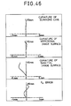
- Fig. 46 The curvature of scanning line, the curvature of the meridional image surface, the curvature of the sagittal image surface and fe error obtained through the computer simulation are shown in Fig. 46.
- the vertical axes extend along the scanning direction, and the characteristics are measured on the horizontal axes.
- the phase of the polygonal optical deflector 37 is zero when the polygonal optical deflector 37 is in a position as shown in Fig. 43.
- the effective scanning distance was 220 mm and the corresponding available angular range of the reflecting surface 36 of the polygonal optical deflector 37 was 36°.
- Table 2 Tabulated in Table 2 are the curvature of the sagittal image surface, the curvature of the meridional image surface, the linearity of f 8 characteristics and the curvature of scanning line of the Examples 1 and 2 of the sixth embodiment of the present invention and the examples of a postobjective optical deflector employed in the known optical scanning device disclosed in Japanese Patent Laid-open (Kokai) No. 61-156020, obtained through computer simulation.
- simulation Nos. 1, 2 and 3 are for the Examples 1, 2 and 3 of the known postobjective optical deflector, respectively, and simulation Nos. 4 and 5 are for the Examples 1 and 2 of the sixth embodiment, respectively.
- the linearity is represented by the maximum value at a scanning speed in the middle portion of the scanning line.
- the curvature of sagittal image surface and the curvature of meridional image surface in the sixth embodiment of the present invention are approximately 1/2, and 1/4 to 1/5 respectively of those of the examples of the known postobjective optical deflector.
- values for the sixth embodiment of the present invention are not more than 2 to 3%, which needs no additional correcting means such as electrical correcting means.
- the sixth embodiment is capable of correcting the curvature of scanning line to a practically negligible extent.
- the postobjective optical deflector may be provided with a plurality of correcting lenses in view of various manufacturing conditions.
- the correcting lens 39 may be substituted by two lenses, namely, a first lens having the same surface of incidence as that of the correcting lens 39, and a spherical surface of departure, and a second lens having a spherical surface of incidence, and the same surface of departure as that of the correcting lens 39.
- the postobjective optical deflector in the sixth embodiment according to the present invention comprises: the polygonal optical deflector having a plurality of reflecting surfaces each formed of a curved surface varying in curvature from position to position thereon; and the correcting lens disposed between the polygonal optical deflector and the objective surface, having a rotationally symmetric curved surface of incidence having a cross section having the shape of an arc of a circle with its center on the axis of rotational symmetry, rotationally symmetric with respect to a plane including the axis of rotation of the polygonal optical deflector and perpendicular to the axis of rotational symmetry and having its power in both the scanning direction and the feed direction, and a surface of departure symmetrical with respect to a plane perpendicular to the scanning direction and having its power in the scanning direction.
- the employment of the polygonal optical deflector having reflecting surfaces each formed of a curved surface varying in curvature from position to position thereon enables the postobjective optical deflector to correct the curvature of the image surface in the scanning direction, namely, the sagittal image surface more effectively than the postobjective optical deflector employing a polygonal optical deflector having reflecting surfaces each formed of a portion of a spherical surface or a cylindrical surface having a fixed curvature.
- the surface of incidence of the correcting lens is formed of a rotationally symmetric curved surface rotationally symmetric with respect to an axis of symmetry parallel to the scanning direction, the power in the feed direction can be varied by varying the curvature of the surface of incidence with respect to the feed direction along the scanning direction, and thereby the curvature of the image surface in the feed direction, namely, the meridional image surface can be corrected.
- forming the surface of departure of the correcting lens in a curved surface having its power in the scanning direction enables the correction of fe characteristics and the further accurate correction of the sagittal image surface.
- the curvature of the sagittal image surface, the curvature of the meridional image surface and fe characteristics can be corrected by the combined correcting effects of the reflecting surfaces of the polygonal optical deflector, and the surfaces of incidence and departure of the correcting lens. Furthermore, the correction of fe characteristics, which has been a significant problem, can be achieved by optical means without requiring any electrical means, so that the postobjective optical deflector of the present invention has high performance, and is simple in construction and inexpensive.
Landscapes
- Physics & Mathematics (AREA)
- General Physics & Mathematics (AREA)
- Optics & Photonics (AREA)
- Lenses (AREA)
- Mechanical Optical Scanning Systems (AREA)
- Facsimile Scanning Arrangements (AREA)
Applications Claiming Priority (12)
| Application Number | Priority Date | Filing Date | Title |
|---|---|---|---|
| JP62238534A JP2520917B2 (ja) | 1987-09-22 | 1987-09-22 | ポストオブジェクト型光偏向器 |
| JP238534/87 | 1987-09-22 | ||
| JP62274439A JPH01116517A (ja) | 1987-10-29 | 1987-10-29 | ポストオブジエクテイブ型光偏向器 |
| JP62274440A JPH01116518A (ja) | 1987-10-29 | 1987-10-29 | ポストオブジエクテイブ型光偏向器 |
| JP274440/87 | 1987-10-29 | ||
| JP274438/87 | 1987-10-29 | ||
| JP62274438A JPH01116516A (ja) | 1987-10-29 | 1987-10-29 | ポストオブジエクテイブ型光偏向器 |
| JP274439/87 | 1987-10-29 | ||
| JP62328908A JPH0786595B2 (ja) | 1987-12-25 | 1987-12-25 | ポストオブジエクテイブ型光走査装置 |
| JP328908/87 | 1987-12-25 | ||
| JP63001517A JP2530351B2 (ja) | 1988-01-07 | 1988-01-07 | ポストオブジエクテイブ型光走査装置 |
| JP1517/88 | 1988-01-07 |
Publications (2)
| Publication Number | Publication Date |
|---|---|
| EP0309205A1 true EP0309205A1 (fr) | 1989-03-29 |
| EP0309205B1 EP0309205B1 (fr) | 1994-02-02 |
Family
ID=27547621
Family Applications (1)
| Application Number | Title | Priority Date | Filing Date |
|---|---|---|---|
| EP88308717A Expired - Lifetime EP0309205B1 (fr) | 1987-09-22 | 1988-09-20 | Déflecteur optique placé derrière un objectif |
Country Status (4)
| Country | Link |
|---|---|
| US (1) | US5064262A (fr) |
| EP (1) | EP0309205B1 (fr) |
| KR (1) | KR920005033B1 (fr) |
| DE (1) | DE3887610T2 (fr) |
Cited By (2)
| Publication number | Priority date | Publication date | Assignee | Title |
|---|---|---|---|---|
| EP0420124A3 (en) * | 1989-09-29 | 1992-03-18 | Kabushiki Kaisha Toshiba | Optical unit for use in laser beam printer or the like |
| EP0461660A3 (en) * | 1990-06-15 | 1992-03-18 | Canon Kabushiki Kaisha | Fo lens and image forming apparatus using the same |
Families Citing this family (3)
| Publication number | Priority date | Publication date | Assignee | Title |
|---|---|---|---|---|
| JPH0486723A (ja) * | 1990-07-31 | 1992-03-19 | Toshiba Corp | 多面体鏡及びその製造方法 |
| JP2969407B2 (ja) * | 1992-03-02 | 1999-11-02 | 松下電器産業株式会社 | ポストオブジェクティブ型走査光学系と画像形成装置 |
| JP2830670B2 (ja) * | 1992-12-29 | 1998-12-02 | キヤノン株式会社 | 光走査装置 |
Citations (5)
| Publication number | Priority date | Publication date | Assignee | Title |
|---|---|---|---|---|
| FR2501385A1 (fr) * | 1981-03-03 | 1982-09-10 | Canon Kk | Dispositif optique compact d'exploration |
| DE3309848A1 (de) * | 1982-03-21 | 1983-09-29 | Konishiroku Photo Industry Co., Ltd., Tokyo | Optische strahlabtastvorrichtung |
| DE3317538A1 (de) * | 1982-05-19 | 1983-11-24 | Hitachi Koki Co., Ltd., Tokyo | Optisches abtastsystem |
| US4571035A (en) * | 1981-11-28 | 1986-02-18 | Ricoh Company, Ltd. | Two-element fθ lens group capable of correcting leaning of deflecting plane |
| US4627685A (en) * | 1983-12-22 | 1986-12-09 | Nobuo Sakuma | Post-objective type scanning device |
Family Cites Families (10)
| Publication number | Priority date | Publication date | Assignee | Title |
|---|---|---|---|---|
| US3970359A (en) * | 1975-02-03 | 1976-07-20 | Xerox Corporation | Flying spot flat field scanner |
| GB1561651A (en) * | 1976-02-13 | 1980-02-27 | Plessey Co Ltd | Opticalrecording apparatus |
| US4383755A (en) * | 1982-01-11 | 1983-05-17 | Burroughs Corporation | Unitary, modular, demountable optical system for laser diode/printing copying apparatus |
| US4578689A (en) * | 1984-11-26 | 1986-03-25 | Data Recording Systems, Inc. | Dual mode laser printer |
| JPS61156020A (ja) * | 1984-12-28 | 1986-07-15 | Ricoh Co Ltd | ポストオブジエクテイブ型光偏向器 |
| US4651169A (en) * | 1985-04-02 | 1987-03-17 | Eastman Kodak Company | Laser printer for printing a plurality of output-images sizes |
| US4633272A (en) * | 1985-04-02 | 1986-12-30 | Eastman Kodak Company | Laser printing apparatus having a multiple formatted output |
| JPS61296324A (ja) * | 1985-06-25 | 1986-12-27 | フジトク株式会社 | レ−ザ光走査装置 |
| JP2502314B2 (ja) * | 1987-07-06 | 1996-05-29 | 株式会社テック | ポストオブジェクティブ型光偏向器 |
| DE68922046T2 (de) * | 1988-08-30 | 1996-07-04 | Tokyo Electric Co Ltd | Optischer Abtaster. |
-
1988
- 1988-09-20 EP EP88308717A patent/EP0309205B1/fr not_active Expired - Lifetime
- 1988-09-20 DE DE3887610T patent/DE3887610T2/de not_active Expired - Fee Related
- 1988-09-22 KR KR1019880012267A patent/KR920005033B1/ko not_active Expired
- 1988-09-22 US US07/247,656 patent/US5064262A/en not_active Expired - Fee Related
Patent Citations (5)
| Publication number | Priority date | Publication date | Assignee | Title |
|---|---|---|---|---|
| FR2501385A1 (fr) * | 1981-03-03 | 1982-09-10 | Canon Kk | Dispositif optique compact d'exploration |
| US4571035A (en) * | 1981-11-28 | 1986-02-18 | Ricoh Company, Ltd. | Two-element fθ lens group capable of correcting leaning of deflecting plane |
| DE3309848A1 (de) * | 1982-03-21 | 1983-09-29 | Konishiroku Photo Industry Co., Ltd., Tokyo | Optische strahlabtastvorrichtung |
| DE3317538A1 (de) * | 1982-05-19 | 1983-11-24 | Hitachi Koki Co., Ltd., Tokyo | Optisches abtastsystem |
| US4627685A (en) * | 1983-12-22 | 1986-12-09 | Nobuo Sakuma | Post-objective type scanning device |
Non-Patent Citations (2)
| Title |
|---|
| PATENT ABSTRACTS OF JAPAN, vol. 10, no. 358 (P-522)[2415], 2nd December 1986; & JP-A-61 156 020 (RICOH CO., LTD) 15-07-1986 * |
| PATENT ABSTRACTS OF JAPAN, vol. 8, no. 237 (P-310)[1674], 30th October 1984; & JP-A-59 113 409 (KOPARU EREKUTORA K.K.) 30-06-1984 * |
Cited By (2)
| Publication number | Priority date | Publication date | Assignee | Title |
|---|---|---|---|---|
| EP0420124A3 (en) * | 1989-09-29 | 1992-03-18 | Kabushiki Kaisha Toshiba | Optical unit for use in laser beam printer or the like |
| EP0461660A3 (en) * | 1990-06-15 | 1992-03-18 | Canon Kabushiki Kaisha | Fo lens and image forming apparatus using the same |
Also Published As
| Publication number | Publication date |
|---|---|
| DE3887610T2 (de) | 1994-08-25 |
| KR920005033B1 (ko) | 1992-06-25 |
| US5064262A (en) | 1991-11-12 |
| EP0309205B1 (fr) | 1994-02-02 |
| DE3887610D1 (de) | 1994-03-17 |
| KR890005549A (ko) | 1989-05-15 |
Similar Documents
| Publication | Publication Date | Title |
|---|---|---|
| EP0177174B1 (fr) | Dispositif de balayage présentant une double réflexion sur chaque facette du polygone tournant | |
| JP3467193B2 (ja) | 屈折/反射型fθ光学素子、および走査光学系 | |
| US4875748A (en) | Polygon mirror | |
| US5748354A (en) | Reflection-type scanning optical system | |
| US5267075A (en) | Optical unit for use in laser beam printer apparatus | |
| EP0309205A1 (fr) | Déflecteur optique placé derrière un objectif | |
| JP3191538B2 (ja) | 走査レンズ及び光走査装置 | |
| US5204769A (en) | Postobjective optical deflector | |
| JPH07174997A (ja) | 光走査装置 | |
| US5148304A (en) | Optical beam scanning system | |
| EP0441350A2 (fr) | Système optique pour des rayons lumineux | |
| JPH0563777B2 (fr) | ||
| US5153766A (en) | Postobjective optical scanner | |
| JP2530351B2 (ja) | ポストオブジエクテイブ型光走査装置 | |
| JPH0786595B2 (ja) | ポストオブジエクテイブ型光走査装置 | |
| JP3558837B2 (ja) | 走査結像光学系および光走査装置 | |
| JPH1152277A (ja) | 光走査装置 | |
| JP2775434B2 (ja) | 走査光学系 | |
| JP3411661B2 (ja) | 走査光学系 | |
| JP2834793B2 (ja) | 光走査装置におけるfθレンズ系 | |
| JPH0990215A (ja) | 単玉fθレンズおよび光走査装置 | |
| JPH112769A (ja) | 光走査装置 | |
| JP2877390B2 (ja) | 光走査装置におけるfθレンズ系 | |
| JP2602716B2 (ja) | 光ビーム走査用光学系 | |
| JP3441008B2 (ja) | 走査結像レンズおよび光走査装置 |
Legal Events
| Date | Code | Title | Description |
|---|---|---|---|
| PUAI | Public reference made under article 153(3) epc to a published international application that has entered the european phase |
Free format text: ORIGINAL CODE: 0009012 |
|
| 17P | Request for examination filed |
Effective date: 19880923 |
|
| AK | Designated contracting states |
Kind code of ref document: A1 Designated state(s): DE FR GB |
|
| 17Q | First examination report despatched |
Effective date: 19910625 |
|
| GRAA | (expected) grant |
Free format text: ORIGINAL CODE: 0009210 |
|
| AK | Designated contracting states |
Kind code of ref document: B1 Designated state(s): DE FR GB |
|
| REF | Corresponds to: |
Ref document number: 3887610 Country of ref document: DE Date of ref document: 19940317 |
|
| ET | Fr: translation filed | ||
| PLBE | No opposition filed within time limit |
Free format text: ORIGINAL CODE: 0009261 |
|
| STAA | Information on the status of an ep patent application or granted ep patent |
Free format text: STATUS: NO OPPOSITION FILED WITHIN TIME LIMIT |
|
| 26N | No opposition filed | ||
| REG | Reference to a national code |
Ref country code: GB Ref legal event code: IF02 |
|
| PGFP | Annual fee paid to national office [announced via postgrant information from national office to epo] |
Ref country code: FR Payment date: 20020910 Year of fee payment: 15 |
|
| PGFP | Annual fee paid to national office [announced via postgrant information from national office to epo] |
Ref country code: GB Payment date: 20020918 Year of fee payment: 15 |
|
| PGFP | Annual fee paid to national office [announced via postgrant information from national office to epo] |
Ref country code: DE Payment date: 20020925 Year of fee payment: 15 |
|
| PG25 | Lapsed in a contracting state [announced via postgrant information from national office to epo] |
Ref country code: GB Free format text: LAPSE BECAUSE OF NON-PAYMENT OF DUE FEES Effective date: 20030920 |
|
| PG25 | Lapsed in a contracting state [announced via postgrant information from national office to epo] |
Ref country code: DE Free format text: LAPSE BECAUSE OF NON-PAYMENT OF DUE FEES Effective date: 20040401 |
|
| GBPC | Gb: european patent ceased through non-payment of renewal fee |
Effective date: 20030920 |
|
| PG25 | Lapsed in a contracting state [announced via postgrant information from national office to epo] |
Ref country code: FR Free format text: LAPSE BECAUSE OF NON-PAYMENT OF DUE FEES Effective date: 20040528 |
|
| REG | Reference to a national code |
Ref country code: FR Ref legal event code: ST |