EP0309215A1 - Régleur de pression d'eau pour appareil d'hémodialyse - Google Patents
Régleur de pression d'eau pour appareil d'hémodialyse Download PDFInfo
- Publication number
- EP0309215A1 EP0309215A1 EP88308733A EP88308733A EP0309215A1 EP 0309215 A1 EP0309215 A1 EP 0309215A1 EP 88308733 A EP88308733 A EP 88308733A EP 88308733 A EP88308733 A EP 88308733A EP 0309215 A1 EP0309215 A1 EP 0309215A1
- Authority
- EP
- European Patent Office
- Prior art keywords
- pressure
- deaeration
- water
- pump
- outlet
- Prior art date
- Legal status (The legal status is an assumption and is not a legal conclusion. Google has not performed a legal analysis and makes no representation as to the accuracy of the status listed.)
- Granted
Links
- XLYOFNOQVPJJNP-UHFFFAOYSA-N water Substances O XLYOFNOQVPJJNP-UHFFFAOYSA-N 0.000 title claims abstract description 105
- 238000001631 haemodialysis Methods 0.000 title claims abstract description 23
- 230000000322 hemodialysis Effects 0.000 title claims abstract description 23
- 230000001105 regulatory effect Effects 0.000 claims abstract 23
- 238000006073 displacement reaction Methods 0.000 claims description 3
- 230000001276 controlling effect Effects 0.000 claims 3
- 238000005276 aerator Methods 0.000 claims 1
- 239000008400 supply water Substances 0.000 abstract description 2
- 238000010586 diagram Methods 0.000 description 6
- 239000000243 solution Substances 0.000 description 5
- 239000012141 concentrate Substances 0.000 description 4
- 238000000502 dialysis Methods 0.000 description 4
- 238000000108 ultra-filtration Methods 0.000 description 4
- 230000000694 effects Effects 0.000 description 3
- QSHDDOUJBYECFT-UHFFFAOYSA-N mercury Chemical compound [Hg] QSHDDOUJBYECFT-UHFFFAOYSA-N 0.000 description 3
- 229910052753 mercury Inorganic materials 0.000 description 3
- 239000008280 blood Substances 0.000 description 2
- 210000004369 blood Anatomy 0.000 description 2
- 239000012530 fluid Substances 0.000 description 2
- 238000004659 sterilization and disinfection Methods 0.000 description 2
- 239000002699 waste material Substances 0.000 description 2
- 208000001647 Renal Insufficiency Diseases 0.000 description 1
- 238000005273 aeration Methods 0.000 description 1
- 230000017531 blood circulation Effects 0.000 description 1
- 230000001419 dependent effect Effects 0.000 description 1
- 239000000385 dialysis solution Substances 0.000 description 1
- 239000012535 impurity Substances 0.000 description 1
- 230000002452 interceptive effect Effects 0.000 description 1
- 238000002955 isolation Methods 0.000 description 1
- 208000017169 kidney disease Diseases 0.000 description 1
- 201000006370 kidney failure Diseases 0.000 description 1
- 238000005259 measurement Methods 0.000 description 1
- 239000012528 membrane Substances 0.000 description 1
- 230000002503 metabolic effect Effects 0.000 description 1
- 238000000034 method Methods 0.000 description 1
- 238000012986 modification Methods 0.000 description 1
- 230000004048 modification Effects 0.000 description 1
- 238000001223 reverse osmosis Methods 0.000 description 1
- 239000011800 void material Substances 0.000 description 1
Images


Classifications
-
- A—HUMAN NECESSITIES
- A61—MEDICAL OR VETERINARY SCIENCE; HYGIENE
- A61M—DEVICES FOR INTRODUCING MEDIA INTO, OR ONTO, THE BODY; DEVICES FOR TRANSDUCING BODY MEDIA OR FOR TAKING MEDIA FROM THE BODY; DEVICES FOR PRODUCING OR ENDING SLEEP OR STUPOR
- A61M1/00—Suction or pumping devices for medical purposes; Devices for carrying-off, for treatment of, or for carrying-over, body-liquids; Drainage systems
- A61M1/14—Dialysis systems; Artificial kidneys; Blood oxygenators ; Reciprocating systems for treatment of body fluids, e.g. single needle systems for hemofiltration or pheresis
- A61M1/16—Dialysis systems; Artificial kidneys; Blood oxygenators ; Reciprocating systems for treatment of body fluids, e.g. single needle systems for hemofiltration or pheresis with membranes
- A61M1/1654—Dialysates therefor
- A61M1/1656—Apparatus for preparing dialysates
- A61M1/1658—Degasification
-
- A—HUMAN NECESSITIES
- A61—MEDICAL OR VETERINARY SCIENCE; HYGIENE
- A61M—DEVICES FOR INTRODUCING MEDIA INTO, OR ONTO, THE BODY; DEVICES FOR TRANSDUCING BODY MEDIA OR FOR TAKING MEDIA FROM THE BODY; DEVICES FOR PRODUCING OR ENDING SLEEP OR STUPOR
- A61M1/00—Suction or pumping devices for medical purposes; Devices for carrying-off, for treatment of, or for carrying-over, body-liquids; Drainage systems
- A61M1/14—Dialysis systems; Artificial kidneys; Blood oxygenators ; Reciprocating systems for treatment of body fluids, e.g. single needle systems for hemofiltration or pheresis
- A61M1/16—Dialysis systems; Artificial kidneys; Blood oxygenators ; Reciprocating systems for treatment of body fluids, e.g. single needle systems for hemofiltration or pheresis with membranes
- A61M1/1654—Dialysates therefor
- A61M1/1656—Apparatus for preparing dialysates
- A61M1/166—Heating
- A61M1/1662—Heating with heat exchange between fresh and used dialysate
Definitions
- the present invention relates to hemodialysis apparatus, and more particularly to a system for minimizing the effects of water pressure transients on the accuracy and consistency of patient dialysis.
- Hemodialysis machines used to extract waste from human blood of patients having kidney failures or disorders utilize a dialyzer in which the blood flows through one chamber and a dialysate solution flows through another chamber separated from the first chamber by a membrane.
- the dialysate picks up metabolic waste products and ultrafiltrate from the blood passing through the dialyzer.
- incoming water is first treated externally to the machine to remove impurities, and thereafter pressure controlled, filtered, heated, and applied to a proportioning pump which is also connected to a supply of concentrated dialysis solution.
- the proportioning pump produces a carefully controlled dialysate solution from the water and concentrate. For example, a 34 parts water and 1 part dialysate concentrate is typical.
- the dialysate may be applied to a flow controller or other means which controls the rate of flow of the dialysate through the dialyzer.
- the present invention is a water system for supplying treated water to a dialysate proportioning pump which will maintain an essentially constant water pressure.
- Typical prior art systems utilize means for removing air entrapped in the incoming water from the water stream prior to the proportioning pump.
- the air is removed in a deaeration loop utilizing a deaerator having a float valve and air outlet.
- the incoming water is fed to a deaerator pressure regulator having an output to the deaerator.
- the deaerator output is connected to a pump, thence back to the pressure regulator completing the deaeration loop.
- the pump creates a negative pressure in the deaerator pressure regulator, drawing the incoming water into the deaerator at which point the entrapped air in the water escapes via the float valve and air outlet at a lower negative pressure.
- the deaeration pressure regulator controls the negative pressure to a selected value, for example; -23 inches of mercury.
- the incoming water to the deaeration pressure regulator is generally controlled by a first pressure regulator to 12 psig.
- the output water from the deaeration pressure regulator is supplied to the proportioning pump.
- the invention utilizes the above described prior art system adding a second regulator, termed a back pressure regulator, to receive water from the deaeration pump and to control the pressure of that water to a value higher than 12 psig; for example, 15 psig.
- the output from the back pressure regulator then provides the water to the dialysate proportioning pump.
- the pressure of the water to the proportioning pump is now independent of the incoming water pressure since the deaerator loop serves as a constant volume source of water to the pump and the pump is independent of the incoming water pressure and flow.
- disturbances at the water input are effectively buffered and eliminated by the invention.
- FIG 1 shows a simplified block diagram of the water and dialysate portion of a typical hemodialysis machine.
- the model SPS-450 hemodialysis apparatus manufactured by Baxter, Inc. utilizes this system.
- Water is treated in a water treatment system and thereafter enters pressure regulator 1, nominally at 40 psig pressure.
- pressure regulator 1 controls the output pressure to 12 psig.
- the water is passed through a filter-heat exchanger unit 2 which heats the water to a predetermined temperature.
- the heated water is then sent via line 8 to a deaerator pressure regulator 3 shown in schematic form in Figure 1.
- deaerator pressure regulator 3 includes an input/output chamber 13 into which heated water flows from line 8.
- Deaerator pressure regulator 3 is a part of a deaeration loop which includes deaerator 6 and positive displacement gear deaerator pump 7. Water flowing into the deaeration loop from line 8 will normally contain air which must be removed to optimize dialyzer performance and measurement of ultrafiltration through the dialyzer in the hemodialysis apparatus.
- the deaeration 6 performs the air removal function.
- the function of the deaeration pressure regulator is to subject the incoming water to a negative pressure of about -23 inches of mercury by means of deaeration pump 7.
- deaerator 6 When the system is not in operation, it may be noted that spring 33 will force diaphragm 34 to the right, closing valve seat 31 with valve body 30.
- deaeration pump 7 When deaeration pump 7 is operating, a -23 inches of mercury pressure occurs in chamber 33 moving diaphragm 34 to the left and opening regulator valve seat 31. Bleed orifice 32 permits an initial flow of water from chamber 13 into chamber 14 prior to the opening of valve 30, 31 to prevent excess pressure in chamber 13 from pump 7.
- valve 30, 31 opens, the water from chamber 14 is drawn into the deaerator 6.
- deaerator 6 includes a float and float chamber at the upper end thereof and an air outlet valve controlled by the float.
- the negative pressure in the deaerator will cause the air in solution to expand, producing large bubbles of air which will float to the top and be expelled through the float air outlet valve to a low pressure part of the hemodialysis apparatus.
- the deaerated water is drawn from the lower end of deaerator 6 over line 10 to pump via pump 7 and flows via line 11 back to chamber 13.
- An output line 12 from chamber 13 is provided; however, pump 7 produces a flow rate in the deaeration loop which is considerably higher than the flow rate required by the dialyzer. For this reason, most of the water will circulate through the deaeration loop two or more times before leaving chamber 13 on line 12. Water which enters chamber 13 on line 8 at about 12 psig will then, due to continuity of flow, exit chamber 13 on line 12 at about 12 psig, neglecting slight pressure drops through the other elements of the system.
- the internal porting in chamber 13 is arranged to ensure that flow inline 8 will always enter valve 30, 31. Water flows out on line 12 and is routed to dialysate proportioning pump 4 or other proportioning system.
- dialysate is stored in concentrated form and must be diluted in an exact proportion with water prior to use as the dialysate for a dialyzer.
- a ratio of 34 parts of water to 1 part of dialysate concentrate is commonly used.
- the output from dialysate proportioning pump provides the proper dialysate solution for use by the dialyzer and its flow rate is controlled by flow controller 5 to a predetermined flow rate for the hemodialysis apparatus.
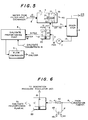
- FIGS 2 and 3 illustrate the improvement of the present invention which essentially eliminates the effects of input pressure transients on the accuracy of the dialysis operation in the hemodialysis apparatus.
- a back pressure regulator 20 shown in simplified cross-sectional view in Figure 2 is added into the deaeration loop.
- Back pressure regulator 20 has a diaphragm 24, spring 26, and adjusting screw 28 which control the regulator needle 22 in conjunction with valve seat 21.
- Deaeration pump 7 is connected to an input to back pressure regulator 20 with the pressure controlled output line 15 connected to chamber 13 of aeration pressure regulator 3.
- Back pressure regulator 20 will be closed as will control valve 30, 31 of the deaeration pressure regulator 3.
- pressure from line 18 will permit water through bleed hole 32 into chamber 14 and pump 7 will cause back pressure regulator to operate at the adjusted pressure point.
- valve 30, 31 will open as previously discussed, enabling the deaeration process.
- a modified deaeration pressure regulator 40 is utilized having a single port into chamber 13 connected by line 8 to filter heat exchanger 2.
- the remainder of the deaeration loop connections remain the same as shown in Figure 5 with the output from back pressure regulator 20 being connected to dialysate proportioning pump 4.
- the advantage of this implementation is that the pressure regulator 1 of Figure 1 and related control solenoids (not shown) can be eliminated and the source pressure applied to chamber 13.
- valve 30, 31 will be closed and chamber 13 can easily handle the source pressure which would rarely exceed 100 psig.
- the deaeration pump 7 will produce the required negative pressure in chamber 14 opening valve 30, 31 as required.
- water is supplied to dialysate proportioning pump via lines 12 directly from the deaeration loop with the pressure controlled by pump 7, ensuring isolation from pressure transients in the water supply system.
- the deaeration pump 7, as mentioned above, produces a greater flow than required by the dialyzer in the hemodialysis apparatus described.
- the dialyzer may utilize a flow in the range of 300-500 ml/min while the pump 7 may produce flows in the range of 1.5 - 2l/min.
- a source of warm, deaerated water is periodically needed at rinse ports 44 and 46 for rinsing the proportioning pump concentrate lines and during system disinfection.
- FIG. 6 shows schematically the use of deaeration pump 7 to provide rinse water to ports 44 and 46.
- a flow restrictor 42 is inserted in line 11 between pump 7 and back pressure regulator 20.
- Rinse ports 44 and 46 are each required to provide a source of warm deaerated water at a flow of about 15 ml/min.
- Lines 41 and 43 which may be small tubing, are connected across flow restrictor 42.
- a pressure drop of about 4 psig across rinse restrictor 42 will produce the required flow through lines 41 and 43 without interfering with the normal deaeration loop operation.
- Normally closed ports 44 and 46 are connected to line 41 and may be temporarily connected to portions of the machine for rinsing by one or two rinse lines having a connector that opens port 44 or 46 when connected thereto. Continuous flows at all times through the loop formed by lines 41 and 43 independently of the rinse ports assures that no stagnation can occur and that proper rinsing will take place during disinfection cycles.
Landscapes
- Health & Medical Sciences (AREA)
- Heart & Thoracic Surgery (AREA)
- Urology & Nephrology (AREA)
- Anesthesiology (AREA)
- Vascular Medicine (AREA)
- Engineering & Computer Science (AREA)
- Emergency Medicine (AREA)
- Biomedical Technology (AREA)
- Hematology (AREA)
- Life Sciences & Earth Sciences (AREA)
- Animal Behavior & Ethology (AREA)
- General Health & Medical Sciences (AREA)
- Public Health (AREA)
- Veterinary Medicine (AREA)
- External Artificial Organs (AREA)
Applications Claiming Priority (2)
| Application Number | Priority Date | Filing Date | Title |
|---|---|---|---|
| US07/099,545 US4828693A (en) | 1987-09-22 | 1987-09-22 | Water pressure regulator for hemodialysis apparatus |
| US99545 | 1987-09-22 |
Publications (2)
| Publication Number | Publication Date |
|---|---|
| EP0309215A1 true EP0309215A1 (fr) | 1989-03-29 |
| EP0309215B1 EP0309215B1 (fr) | 1992-08-26 |
Family
ID=22275522
Family Applications (1)
| Application Number | Title | Priority Date | Filing Date |
|---|---|---|---|
| EP88308733A Expired EP0309215B1 (fr) | 1987-09-22 | 1988-09-21 | Régleur de pression d'eau pour appareil d'hémodialyse |
Country Status (5)
| Country | Link |
|---|---|
| US (1) | US4828693A (fr) |
| EP (1) | EP0309215B1 (fr) |
| CA (1) | CA1320144C (fr) |
| HK (1) | HK16393A (fr) |
| SG (1) | SG125892G (fr) |
Families Citing this family (102)
| Publication number | Priority date | Publication date | Assignee | Title |
|---|---|---|---|---|
| US5486286A (en) * | 1991-04-19 | 1996-01-23 | Althin Medical, Inc. | Apparatus for performing a self-test of kidney dialysis membrane |
| US5244568A (en) * | 1991-11-15 | 1993-09-14 | Baxter International Inc. | Automated hemodialysis chemical treatment system with control valve and proportioning pumps |
| US6139754A (en) * | 1991-11-15 | 2000-10-31 | Baxter International Inc. | Hemodialysis conductivity servo-proportioning system and method |
| US6235199B1 (en) | 1999-03-12 | 2001-05-22 | Dialysis Systems, Inc. | Parallel plumbing supply system |
| US20060217771A1 (en) | 2005-02-07 | 2006-09-28 | Medtronic, Inc. | Potassium monitoring |
| US10537671B2 (en) | 2006-04-14 | 2020-01-21 | Deka Products Limited Partnership | Automated control mechanisms in a hemodialysis apparatus |
| ATE524204T1 (de) * | 2006-12-01 | 2011-09-15 | Gambro Lundia Ab | Blutbehandlungsgerät |
| US9028691B2 (en) | 2007-02-27 | 2015-05-12 | Deka Products Limited Partnership | Blood circuit assembly for a hemodialysis system |
| US8562834B2 (en) | 2007-02-27 | 2013-10-22 | Deka Products Limited Partnership | Modular assembly for a portable hemodialysis system |
| US8042563B2 (en) | 2007-02-27 | 2011-10-25 | Deka Products Limited Partnership | Cassette system integrated apparatus |
| KR20230165373A (ko) | 2007-02-27 | 2023-12-05 | 데카 프로덕츠 리미티드 파트너쉽 | 혈액투석 시스템 |
| US8409441B2 (en) | 2007-02-27 | 2013-04-02 | Deka Products Limited Partnership | Blood treatment systems and methods |
| US7981082B2 (en) * | 2007-08-21 | 2011-07-19 | Hospira, Inc. | System and method for reducing air bubbles in a fluid delivery line |
| US8240636B2 (en) | 2009-01-12 | 2012-08-14 | Fresenius Medical Care Holdings, Inc. | Valve system |
| US8597505B2 (en) | 2007-09-13 | 2013-12-03 | Fresenius Medical Care Holdings, Inc. | Portable dialysis machine |
| US9358331B2 (en) | 2007-09-13 | 2016-06-07 | Fresenius Medical Care Holdings, Inc. | Portable dialysis machine with improved reservoir heating system |
| US8105487B2 (en) | 2007-09-25 | 2012-01-31 | Fresenius Medical Care Holdings, Inc. | Manifolds for use in conducting dialysis |
| US9308307B2 (en) | 2007-09-13 | 2016-04-12 | Fresenius Medical Care Holdings, Inc. | Manifold diaphragms |
| EP2237814B1 (fr) | 2007-11-29 | 2019-03-06 | Fresenius Medical Care Holdings, Inc. | Collecteur pour réaliser une hémodialyse et une hémofiltration |
| US8517990B2 (en) | 2007-12-18 | 2013-08-27 | Hospira, Inc. | User interface improvements for medical devices |
| US10201647B2 (en) | 2008-01-23 | 2019-02-12 | Deka Products Limited Partnership | Medical treatment system and methods using a plurality of fluid lines |
| US11833281B2 (en) | 2008-01-23 | 2023-12-05 | Deka Products Limited Partnership | Pump cassette and methods for use in medical treatment system using a plurality of fluid lines |
| CA2976872C (fr) | 2008-10-07 | 2021-04-13 | Fresenius Medical Care Holdings, Inc. | Systeme et procede d'amorcage pour systemes de dialyse |
| NZ592652A (en) | 2008-10-30 | 2013-10-25 | Fresenius Med Care Hldg Inc | Modular, portable dialysis system |
| WO2010114932A1 (fr) | 2009-03-31 | 2010-10-07 | Xcorporeal, Inc. | Ensemble réservoir modulaire pour un système d'hémodialyse et d'hémofiltration |
| US9399091B2 (en) | 2009-09-30 | 2016-07-26 | Medtronic, Inc. | System and method to regulate ultrafiltration |
| US9750862B2 (en) | 2011-04-29 | 2017-09-05 | Medtronic, Inc. | Adaptive system for blood fluid removal |
| US9848778B2 (en) | 2011-04-29 | 2017-12-26 | Medtronic, Inc. | Method and device to monitor patients with kidney disease |
| US9456755B2 (en) | 2011-04-29 | 2016-10-04 | Medtronic, Inc. | Method and device to monitor patients with kidney disease |
| JP6109819B2 (ja) | 2011-05-24 | 2017-04-05 | デカ・プロダクツ・リミテッド・パートナーシップ | 血液透析システム |
| EP2714123B1 (fr) * | 2011-05-24 | 2017-08-09 | DEKA Products Limited Partnership | Systèmes et procédés de traitement du sang |
| EP3165245B1 (fr) | 2011-08-02 | 2019-02-20 | Medtronic, Inc. | Système d'hémodialyse possédant un circuit de flux avec un volume à conformité régulée |
| EP2744537B1 (fr) | 2011-08-16 | 2018-01-24 | Medtronic, Inc. | Système d'hémodialyse modulaire |
| US9240002B2 (en) | 2011-08-19 | 2016-01-19 | Hospira, Inc. | Systems and methods for a graphical interface including a graphical representation of medical data |
| US10022498B2 (en) | 2011-12-16 | 2018-07-17 | Icu Medical, Inc. | System for monitoring and delivering medication to a patient and method of using the same to minimize the risks associated with automated therapy |
| WO2013103906A1 (fr) | 2012-01-04 | 2013-07-11 | Medtronic, Inc. | Système de filtration à étages multiples pour l'élimination d'un fluide du sang |
| EP2830687B1 (fr) | 2012-03-30 | 2019-07-24 | ICU Medical, Inc. | Système de détection d'air et procédé de détection d'air dans une pompe d'un système de perfusion |
| AU2013296555B2 (en) | 2012-07-31 | 2017-10-19 | Icu Medical, Inc. | Patient care system for critical medications |
| US10905816B2 (en) | 2012-12-10 | 2021-02-02 | Medtronic, Inc. | Sodium management system for hemodialysis |
| US9201036B2 (en) | 2012-12-21 | 2015-12-01 | Fresenius Medical Care Holdings, Inc. | Method and system of monitoring electrolyte levels and composition using capacitance or induction |
| US9157786B2 (en) | 2012-12-24 | 2015-10-13 | Fresenius Medical Care Holdings, Inc. | Load suspension and weighing system for a dialysis machine reservoir |
| US11565029B2 (en) | 2013-01-09 | 2023-01-31 | Medtronic, Inc. | Sorbent cartridge with electrodes |
| US9707328B2 (en) | 2013-01-09 | 2017-07-18 | Medtronic, Inc. | Sorbent cartridge to measure solute concentrations |
| US9713666B2 (en) | 2013-01-09 | 2017-07-25 | Medtronic, Inc. | Recirculating dialysate fluid circuit for blood measurement |
| US11154648B2 (en) | 2013-01-09 | 2021-10-26 | Medtronic, Inc. | Fluid circuits for sorbent cartridge with sensors |
| US10850016B2 (en) | 2013-02-01 | 2020-12-01 | Medtronic, Inc. | Modular fluid therapy system having jumpered flow paths and systems and methods for cleaning and disinfection |
| US10010663B2 (en) | 2013-02-01 | 2018-07-03 | Medtronic, Inc. | Fluid circuit for delivery of renal replacement therapies |
| US10543052B2 (en) | 2013-02-01 | 2020-01-28 | Medtronic, Inc. | Portable dialysis cabinet |
| US9623164B2 (en) | 2013-02-01 | 2017-04-18 | Medtronic, Inc. | Systems and methods for multifunctional volumetric fluid control |
| US9526822B2 (en) | 2013-02-01 | 2016-12-27 | Medtronic, Inc. | Sodium and buffer source cartridges for use in a modular controlled compliant flow path |
| US9827361B2 (en) | 2013-02-02 | 2017-11-28 | Medtronic, Inc. | pH buffer measurement system for hemodialysis systems |
| US9144640B2 (en) | 2013-02-02 | 2015-09-29 | Medtronic, Inc. | Sorbent cartridge configurations for improved dialysate regeneration |
| US10046112B2 (en) | 2013-05-24 | 2018-08-14 | Icu Medical, Inc. | Multi-sensor infusion system for detecting air or an occlusion in the infusion system |
| WO2014194089A1 (fr) | 2013-05-29 | 2014-12-04 | Hospira, Inc. | Système de perfusion qui emploie un ou plusieurs capteurs et des informations additionnelles pour faire une détermination d'air concernant le système de perfusion |
| AU2014274122A1 (en) | 2013-05-29 | 2016-01-21 | Icu Medical, Inc. | Infusion system and method of use which prevents over-saturation of an analog-to-digital converter |
| US10076283B2 (en) | 2013-11-04 | 2018-09-18 | Medtronic, Inc. | Method and device to manage fluid volumes in the body |
| US9354640B2 (en) | 2013-11-11 | 2016-05-31 | Fresenius Medical Care Holdings, Inc. | Smart actuator for valve |
| US9884145B2 (en) | 2013-11-26 | 2018-02-06 | Medtronic, Inc. | Parallel modules for in-line recharging of sorbents using alternate duty cycles |
| US10537875B2 (en) | 2013-11-26 | 2020-01-21 | Medtronic, Inc. | Precision recharging of sorbent materials using patient and session data |
| CN105992552B (zh) | 2013-11-27 | 2019-06-18 | 美敦力公司 | 精确透析监测及同步系统 |
| ES2776363T3 (es) | 2014-02-28 | 2020-07-30 | Icu Medical Inc | Sistema de infusión y método que utiliza detección óptica de aire en línea de doble longitud de onda |
| US11344673B2 (en) | 2014-05-29 | 2022-05-31 | Icu Medical, Inc. | Infusion system and pump with configurable closed loop delivery rate catch-up |
| EP3160534A4 (fr) | 2014-06-24 | 2018-03-07 | Medtronic Inc. | Ensemble sorbant empilé |
| WO2015199766A1 (fr) | 2014-06-24 | 2015-12-30 | Medtronic, Inc. | Ensemble de régénération de dialysat modulaire |
| US10874787B2 (en) | 2014-12-10 | 2020-12-29 | Medtronic, Inc. | Degassing system for dialysis |
| US9713665B2 (en) | 2014-12-10 | 2017-07-25 | Medtronic, Inc. | Degassing system for dialysis |
| US9895479B2 (en) | 2014-12-10 | 2018-02-20 | Medtronic, Inc. | Water management system for use in dialysis |
| US10098993B2 (en) | 2014-12-10 | 2018-10-16 | Medtronic, Inc. | Sensing and storage system for fluid balance |
| US11344668B2 (en) | 2014-12-19 | 2022-05-31 | Icu Medical, Inc. | Infusion system with concurrent TPN/insulin infusion |
| US10850024B2 (en) | 2015-03-02 | 2020-12-01 | Icu Medical, Inc. | Infusion system, device, and method having advanced infusion features |
| US10335534B2 (en) | 2015-11-06 | 2019-07-02 | Medtronic, Inc. | Dialysis prescription optimization for decreased arrhythmias |
| WO2017176695A1 (fr) | 2016-04-04 | 2017-10-12 | Medtronic, Inc. | Système de génération de fluide de dialysat péritonéal |
| US10994064B2 (en) | 2016-08-10 | 2021-05-04 | Medtronic, Inc. | Peritoneal dialysate flow path sensing |
| US12329892B2 (en) | 2016-04-04 | 2025-06-17 | Mozarc Medical Us Llc | Dextrose concentration sensor for a peritoneal dialysis system |
| US10874790B2 (en) | 2016-08-10 | 2020-12-29 | Medtronic, Inc. | Peritoneal dialysis intracycle osmotic agent adjustment |
| ES2912378T3 (es) | 2016-05-13 | 2022-05-25 | Icu Medical Inc | Sistema de bomba de infusión con purga automática de línea común |
| AU2017277804B2 (en) | 2016-06-10 | 2022-05-26 | Icu Medical, Inc. | Acoustic flow sensor for continuous medication flow measurements and feedback control of infusion |
| US11013843B2 (en) | 2016-09-09 | 2021-05-25 | Medtronic, Inc. | Peritoneal dialysis fluid testing system |
| US10981148B2 (en) | 2016-11-29 | 2021-04-20 | Medtronic, Inc. | Zirconium oxide module conditioning |
| US10960381B2 (en) | 2017-06-15 | 2021-03-30 | Medtronic, Inc. | Zirconium phosphate disinfection recharging and conditioning |
| US11278654B2 (en) | 2017-12-07 | 2022-03-22 | Medtronic, Inc. | Pneumatic manifold for a dialysis system |
| US10089055B1 (en) | 2017-12-27 | 2018-10-02 | Icu Medical, Inc. | Synchronized display of screen content on networked devices |
| US11033667B2 (en) | 2018-02-02 | 2021-06-15 | Medtronic, Inc. | Sorbent manifold for a dialysis system |
| US11110215B2 (en) | 2018-02-23 | 2021-09-07 | Medtronic, Inc. | Degasser and vent manifolds for dialysis |
| US12285552B2 (en) | 2018-08-14 | 2025-04-29 | Mozarc Medical Us Llc | Precision dialysis therapy based on sorbent effluent analysis |
| US11213616B2 (en) | 2018-08-24 | 2022-01-04 | Medtronic, Inc. | Recharge solution for zirconium phosphate |
| US11806457B2 (en) | 2018-11-16 | 2023-11-07 | Mozarc Medical Us Llc | Peritoneal dialysis adequacy meaurements |
| US11806456B2 (en) | 2018-12-10 | 2023-11-07 | Mozarc Medical Us Llc | Precision peritoneal dialysis therapy based on dialysis adequacy measurements |
| US12433976B2 (en) | 2019-01-08 | 2025-10-07 | Mozarc Medical Us Llc | Bicarbonate sensor for dialysis |
| US11278671B2 (en) | 2019-12-04 | 2022-03-22 | Icu Medical, Inc. | Infusion pump with safety sequence keypad |
| US12128165B2 (en) | 2020-04-27 | 2024-10-29 | Mozarc Medical Us Llc | Dual stage degasser |
| CA3189781A1 (fr) | 2020-07-21 | 2022-01-27 | Icu Medical, Inc. | Dispositifs de transfert de fluide et procedes d'utilisation |
| US11135360B1 (en) | 2020-12-07 | 2021-10-05 | Icu Medical, Inc. | Concurrent infusion with common line auto flush |
| US12569601B2 (en) | 2021-04-07 | 2026-03-10 | Mozarc Medical Us Llc | Increased operational capabilities of a dialysis system |
| US12397093B2 (en) | 2021-05-18 | 2025-08-26 | Mozarc Medical Us Llc | Sorbent cartridge designs |
| US12154673B2 (en) | 2021-08-02 | 2024-11-26 | Mozarc Medical Us Llc | Artificial intelligence assisted home therapy settings for dialysis |
| US11850344B2 (en) | 2021-08-11 | 2023-12-26 | Mozarc Medical Us Llc | Gas bubble sensor |
| US12599716B2 (en) | 2021-10-12 | 2026-04-14 | Icu Medical, Inc. | Intravenous infusion pump with cassette insertion and pump control user interface |
| USD1091564S1 (en) | 2021-10-13 | 2025-09-02 | Icu Medical, Inc. | Display screen or portion thereof with graphical user interface for a medical device |
| US11965763B2 (en) | 2021-11-12 | 2024-04-23 | Mozarc Medical Us Llc | Determining fluid flow across rotary pump |
| US11944733B2 (en) | 2021-11-18 | 2024-04-02 | Mozarc Medical Us Llc | Sodium and bicarbonate control |
| WO2023108030A1 (fr) | 2021-12-10 | 2023-06-15 | Icu Medical, Inc. | Systèmes de mélange de fluides médicaux à commande d'écoulement coordonnée |
Citations (2)
| Publication number | Priority date | Publication date | Assignee | Title |
|---|---|---|---|---|
| FR2237639A1 (en) * | 1973-07-20 | 1975-02-14 | Gensollen Yves | Degasser for artificial kidney dialysis liquid - senses growing gas vol. in degasser to actuate connection with vacuum system |
| EP0143341A2 (fr) * | 1983-11-29 | 1985-06-05 | Gambro Lundia AB | Disposition pour le désaérage d'un liquide |
Family Cites Families (8)
| Publication number | Priority date | Publication date | Assignee | Title |
|---|---|---|---|---|
| US3598727A (en) * | 1969-04-07 | 1971-08-10 | Charles B Willock | Artificial kidney |
| US3878095A (en) * | 1974-05-02 | 1975-04-15 | Advanced Medical Sciences Inc | Dialysis apparatus |
| US4060485A (en) * | 1975-06-09 | 1977-11-29 | I T L Technology, Inc. | Dialysis apparatus |
| US4054522A (en) * | 1975-09-03 | 1977-10-18 | Harry Pinkerton | Apparatus for exposing a fluid to a negative pressure |
| US4209391A (en) * | 1978-11-06 | 1980-06-24 | Cordis Dow Corp. | Apparatus and method for automatically controlling hemodialysis at a pre-selected ultrafiltration rate |
| US4715959A (en) * | 1982-08-31 | 1987-12-29 | Cd Medical Inc. | Apparatus and method for controlling ultrafiltration during hemodialysis |
| US4477342A (en) * | 1982-08-31 | 1984-10-16 | Becton, Dickinson And Company | Apparatus and method for controlling ultrafiltration during hemodialysis |
| US4718022A (en) * | 1985-02-21 | 1988-01-05 | Cochran Michael J | Dialysis machine which anticipates concentration changes |
-
1987
- 1987-09-22 US US07/099,545 patent/US4828693A/en not_active Expired - Lifetime
-
1988
- 1988-09-20 CA CA000577852A patent/CA1320144C/fr not_active Expired - Fee Related
- 1988-09-21 EP EP88308733A patent/EP0309215B1/fr not_active Expired
-
1992
- 1992-12-09 SG SG1258/92A patent/SG125892G/en unknown
-
1993
- 1993-03-04 HK HK163/93A patent/HK16393A/en not_active IP Right Cessation
Patent Citations (2)
| Publication number | Priority date | Publication date | Assignee | Title |
|---|---|---|---|---|
| FR2237639A1 (en) * | 1973-07-20 | 1975-02-14 | Gensollen Yves | Degasser for artificial kidney dialysis liquid - senses growing gas vol. in degasser to actuate connection with vacuum system |
| EP0143341A2 (fr) * | 1983-11-29 | 1985-06-05 | Gambro Lundia AB | Disposition pour le désaérage d'un liquide |
Also Published As
| Publication number | Publication date |
|---|---|
| US4828693A (en) | 1989-05-09 |
| EP0309215B1 (fr) | 1992-08-26 |
| CA1320144C (fr) | 1993-07-13 |
| SG125892G (en) | 1993-02-19 |
| HK16393A (en) | 1993-03-12 |
Similar Documents
| Publication | Publication Date | Title |
|---|---|---|
| US4828693A (en) | Water pressure regulator for hemodialysis apparatus | |
| US3976574A (en) | Negative pressure control system | |
| US5522998A (en) | Hemodialysis apparatus having a single balance chamber and method of dialyzing blood therewith | |
| EP2101841B1 (fr) | Appareil de traitement sanguin | |
| US6966979B2 (en) | Device and method for controlling infusion of a liquid in an extracorporeal blood circuit | |
| US4897184A (en) | Fluid flow apparatus control and monitoring | |
| US4769134A (en) | Open patient fluid management method and system | |
| US4769151A (en) | Heater control for liquid flowing through a chamber | |
| US4303068A (en) | Method and apparatus for single pass hemodialysis with high flux membranes and controlled ultrafiltration | |
| US4298357A (en) | Degassing system | |
| US8998837B2 (en) | Apparatus for extracorporeal blood treatment | |
| US4735727A (en) | Dialysis equipment | |
| JPH0522549B2 (fr) | ||
| EP0240101A3 (fr) | Appareil pour circuit extra corporel | |
| JP2006520635A (ja) | 溶質の選択的抽出による血液の体外処理のための装置及び方法 | |
| US4060485A (en) | Dialysis apparatus | |
| US4758336A (en) | Dialytic apparatus | |
| JP4097811B2 (ja) | 血液透析用装置 | |
| JPS5912905Y2 (ja) | 人工腎臓透析液の脱気装置 | |
| WO2023202225A1 (fr) | Procédé de fonctionnement d'un système de traitement du sang et système correspondant de traitement du sang | |
| JP3208741B2 (ja) | 血液透析濾過装置 | |
| CN223547865U (zh) | 净水机的水路系统及净水机 | |
| JP2020151616A (ja) | 膜分離装置 | |
| JPH05146506A (ja) | 血液透析装置 | |
| JPS6226804B2 (fr) |
Legal Events
| Date | Code | Title | Description |
|---|---|---|---|
| PUAI | Public reference made under article 153(3) epc to a published international application that has entered the european phase |
Free format text: ORIGINAL CODE: 0009012 |
|
| AK | Designated contracting states |
Kind code of ref document: A1 Designated state(s): FR GB IT |
|
| 17P | Request for examination filed |
Effective date: 19890920 |
|
| 17Q | First examination report despatched |
Effective date: 19910109 |
|
| GRAA | (expected) grant |
Free format text: ORIGINAL CODE: 0009210 |
|
| AK | Designated contracting states |
Kind code of ref document: B1 Designated state(s): FR GB IT |
|
| ET | Fr: translation filed | ||
| ITF | It: translation for a ep patent filed | ||
| PLBE | No opposition filed within time limit |
Free format text: ORIGINAL CODE: 0009261 |
|
| STAA | Information on the status of an ep patent application or granted ep patent |
Free format text: STATUS: NO OPPOSITION FILED WITHIN TIME LIMIT |
|
| 26N | No opposition filed | ||
| REG | Reference to a national code |
Ref country code: GB Ref legal event code: IF02 |
|
| PG25 | Lapsed in a contracting state [announced via postgrant information from national office to epo] |
Ref country code: IT Free format text: LAPSE BECAUSE OF NON-PAYMENT OF DUE FEES Effective date: 20050921 |
|
| PGFP | Annual fee paid to national office [announced via postgrant information from national office to epo] |
Ref country code: GB Payment date: 20070926 Year of fee payment: 20 |
|
| PGFP | Annual fee paid to national office [announced via postgrant information from national office to epo] |
Ref country code: FR Payment date: 20070917 Year of fee payment: 20 |
|
| REG | Reference to a national code |
Ref country code: GB Ref legal event code: PE20 Expiry date: 20080920 |
|
| PG25 | Lapsed in a contracting state [announced via postgrant information from national office to epo] |
Ref country code: GB Free format text: LAPSE BECAUSE OF EXPIRATION OF PROTECTION Effective date: 20080920 |