EP0309232B1 - Appareil d'enregistrement et de reproduction d'information optique - Google Patents
Appareil d'enregistrement et de reproduction d'information optique Download PDFInfo
- Publication number
- EP0309232B1 EP0309232B1 EP88308773A EP88308773A EP0309232B1 EP 0309232 B1 EP0309232 B1 EP 0309232B1 EP 88308773 A EP88308773 A EP 88308773A EP 88308773 A EP88308773 A EP 88308773A EP 0309232 B1 EP0309232 B1 EP 0309232B1
- Authority
- EP
- European Patent Office
- Prior art keywords
- light
- recording
- reproducing apparatus
- information recording
- optical information
- Prior art date
- Legal status (The legal status is an assumption and is not a legal conclusion. Google has not performed a legal analysis and makes no representation as to the accuracy of the status listed.)
- Expired - Lifetime
Links
- 230000003287 optical effect Effects 0.000 title claims description 31
- 238000007493 shaping process Methods 0.000 claims description 18
- 239000004065 semiconductor Substances 0.000 claims description 9
- 230000000694 effects Effects 0.000 description 13
- 230000005415 magnetization Effects 0.000 description 11
- 230000004907 flux Effects 0.000 description 8
- 238000010276 construction Methods 0.000 description 5
- 238000010586 diagram Methods 0.000 description 4
- 239000013078 crystal Substances 0.000 description 1
- 238000001514 detection method Methods 0.000 description 1
- 238000000034 method Methods 0.000 description 1
- 238000012544 monitoring process Methods 0.000 description 1
- 230000010287 polarization Effects 0.000 description 1
Images

Classifications
-
- G—PHYSICS
- G11—INFORMATION STORAGE
- G11B—INFORMATION STORAGE BASED ON RELATIVE MOVEMENT BETWEEN RECORD CARRIER AND TRANSDUCER
- G11B11/00—Recording on or reproducing from the same record carrier wherein for these two operations the methods are covered by different main groups of groups G11B3/00 - G11B7/00 or by different subgroups of group G11B9/00; Record carriers therefor
- G11B11/10—Recording on or reproducing from the same record carrier wherein for these two operations the methods are covered by different main groups of groups G11B3/00 - G11B7/00 or by different subgroups of group G11B9/00; Record carriers therefor using recording by magnetic means or other means for magnetisation or demagnetisation of a record carrier, e.g. light induced spin magnetisation; Demagnetisation by thermal or stress means in the presence or not of an orienting magnetic field
- G11B11/105—Recording on or reproducing from the same record carrier wherein for these two operations the methods are covered by different main groups of groups G11B3/00 - G11B7/00 or by different subgroups of group G11B9/00; Record carriers therefor using recording by magnetic means or other means for magnetisation or demagnetisation of a record carrier, e.g. light induced spin magnetisation; Demagnetisation by thermal or stress means in the presence or not of an orienting magnetic field using a beam of light or a magnetic field for recording by change of magnetisation and a beam of light for reproducing, i.e. magneto-optical, e.g. light-induced thermomagnetic recording, spin magnetisation recording, Kerr or Faraday effect reproducing
- G11B11/10595—Control of operating function
-
- G—PHYSICS
- G11—INFORMATION STORAGE
- G11B—INFORMATION STORAGE BASED ON RELATIVE MOVEMENT BETWEEN RECORD CARRIER AND TRANSDUCER
- G11B11/00—Recording on or reproducing from the same record carrier wherein for these two operations the methods are covered by different main groups of groups G11B3/00 - G11B7/00 or by different subgroups of group G11B9/00; Record carriers therefor
- G11B11/10—Recording on or reproducing from the same record carrier wherein for these two operations the methods are covered by different main groups of groups G11B3/00 - G11B7/00 or by different subgroups of group G11B9/00; Record carriers therefor using recording by magnetic means or other means for magnetisation or demagnetisation of a record carrier, e.g. light induced spin magnetisation; Demagnetisation by thermal or stress means in the presence or not of an orienting magnetic field
- G11B11/105—Recording on or reproducing from the same record carrier wherein for these two operations the methods are covered by different main groups of groups G11B3/00 - G11B7/00 or by different subgroups of group G11B9/00; Record carriers therefor using recording by magnetic means or other means for magnetisation or demagnetisation of a record carrier, e.g. light induced spin magnetisation; Demagnetisation by thermal or stress means in the presence or not of an orienting magnetic field using a beam of light or a magnetic field for recording by change of magnetisation and a beam of light for reproducing, i.e. magneto-optical, e.g. light-induced thermomagnetic recording, spin magnetisation recording, Kerr or Faraday effect reproducing
- G11B11/10502—Recording on or reproducing from the same record carrier wherein for these two operations the methods are covered by different main groups of groups G11B3/00 - G11B7/00 or by different subgroups of group G11B9/00; Record carriers therefor using recording by magnetic means or other means for magnetisation or demagnetisation of a record carrier, e.g. light induced spin magnetisation; Demagnetisation by thermal or stress means in the presence or not of an orienting magnetic field using a beam of light or a magnetic field for recording by change of magnetisation and a beam of light for reproducing, i.e. magneto-optical, e.g. light-induced thermomagnetic recording, spin magnetisation recording, Kerr or Faraday effect reproducing characterised by the transducing operation to be executed
- G11B11/10504—Recording
-
- G—PHYSICS
- G11—INFORMATION STORAGE
- G11B—INFORMATION STORAGE BASED ON RELATIVE MOVEMENT BETWEEN RECORD CARRIER AND TRANSDUCER
- G11B11/00—Recording on or reproducing from the same record carrier wherein for these two operations the methods are covered by different main groups of groups G11B3/00 - G11B7/00 or by different subgroups of group G11B9/00; Record carriers therefor
- G11B11/10—Recording on or reproducing from the same record carrier wherein for these two operations the methods are covered by different main groups of groups G11B3/00 - G11B7/00 or by different subgroups of group G11B9/00; Record carriers therefor using recording by magnetic means or other means for magnetisation or demagnetisation of a record carrier, e.g. light induced spin magnetisation; Demagnetisation by thermal or stress means in the presence or not of an orienting magnetic field
- G11B11/105—Recording on or reproducing from the same record carrier wherein for these two operations the methods are covered by different main groups of groups G11B3/00 - G11B7/00 or by different subgroups of group G11B9/00; Record carriers therefor using recording by magnetic means or other means for magnetisation or demagnetisation of a record carrier, e.g. light induced spin magnetisation; Demagnetisation by thermal or stress means in the presence or not of an orienting magnetic field using a beam of light or a magnetic field for recording by change of magnetisation and a beam of light for reproducing, i.e. magneto-optical, e.g. light-induced thermomagnetic recording, spin magnetisation recording, Kerr or Faraday effect reproducing
- G11B11/10502—Recording on or reproducing from the same record carrier wherein for these two operations the methods are covered by different main groups of groups G11B3/00 - G11B7/00 or by different subgroups of group G11B9/00; Record carriers therefor using recording by magnetic means or other means for magnetisation or demagnetisation of a record carrier, e.g. light induced spin magnetisation; Demagnetisation by thermal or stress means in the presence or not of an orienting magnetic field using a beam of light or a magnetic field for recording by change of magnetisation and a beam of light for reproducing, i.e. magneto-optical, e.g. light-induced thermomagnetic recording, spin magnetisation recording, Kerr or Faraday effect reproducing characterised by the transducing operation to be executed
- G11B11/10515—Reproducing
-
- G—PHYSICS
- G11—INFORMATION STORAGE
- G11B—INFORMATION STORAGE BASED ON RELATIVE MOVEMENT BETWEEN RECORD CARRIER AND TRANSDUCER
- G11B27/00—Editing; Indexing; Addressing; Timing or synchronising; Monitoring; Measuring tape travel
- G11B27/36—Monitoring, i.e. supervising the progress of recording or reproducing
Definitions
- the present invention relates to a recording and reproducing arrangement, and more particularly to an optical information recording and reproducing apparatus such as a magneto-optical disc apparatus or the like, which effects recording and reproducing of signals with respect to a magneto-optical recording medium through utilization of magneto-optical effects.
- an optical information recording and reproducing apparatus such as a magneto-optical disc apparatus or the like, which effects recording and reproducing of signals with respect to a magneto-optical recording medium through utilization of magneto-optical effects.
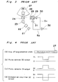
- optical information recording and reproducing apparatus of the type referred to above have been arranged as shown in Fig 3.
- Light emitted from a semi-conductor laser source 21 is incident upon a beam splitter 24 via a collimating lens 22 and a shaping prism 23.
- Substantially linearly polarized light, perpendicular to an optical axis and parallel to the paper surface, is transmitted through the beam splitter 24.
- the light transmitted through the beam splitter 24 is incident upon an objective lens 26 via a mirror 25, and projected as a focused spot onto a disc 27 to effect the recording function.
- the disc 27 comprises the magneto-optical recording medium.
- the reproducing function light projected onto the disc 27 is subjected to magneto-optical effects and is reflected from the disc, through the objective lens 26 and the mirror 25 towards the beam splitter 24 so as to be reflected by said beam splitter 24.
- the reflected light is incident upon a polarizing beam splitter 29 through a 1/2 wavelength plate 28, and split into two directions to be incident upon photo-detectors 30 and 31.
- the light rays incident upon photo-detectors 30 and 31 correspond to the magnetizing direction of the disc 27 as shown in Fig. 4(a), and are converted into information signals S1 and S2.
- the information signals S1 and S2 are electrical signals as shown in Figs. 4(b), and 4(c) so as to be applied to a differential amplifier 32.
- the signals are taken out as an information signal S D amplified two times. Noise components having the same phase are cancelled as shown in Fig. 4(d), and the reproduction of the recorded information is effected by reproducing the information signal S D .
- a time period approximately equal to that for recording is required to effect the reproduction for checking for erroneous recording. More specifically, for example, in the case where the magneto-optical recording medium is in the form of a disc, a time period equivalent to one rotation of the disc is required for the detection of recording errors. Thus, recording at high speeds in a short period of time is not possible or at least it is made very difficult.
- An object of the present invention is to alleviate at least some of the afore-mentioned problems.
- the present invention provides an optical information recording and reproducing apparatus comprising a light source, means for directing light from said light source onto a magneto-optical recording medium to permit information recording by the selective change of the magnetisation state on the medium, analyzing means for dividing light reflected from the medium during recording into different polarisation components, photo-detecting means for generating respective electrical signals representative of said divided polarisation components, and subtracting means for subtracting said respective electrical signals one from the other, characterised by a waveform shaping means comprising a full wave rectifier for adjusting the output waveform of said subtracting means and a comparing means for comparing the output signal of said waveform shaping means with a preliminary set threshold value.
- An advantage of the invention is that it provides an optical information recording and reproducing apparatus which is capable of detecting recording errors whilst simultaneously recording data thereby reducing recording time, without requiring a particularly high accuracy optical system, avoiding complicated construction and consequently large sized optical system.
- Another advantage of the present invention is that it provides an optical information recording and reproducing apparatus of the above described type, which has stable operation and is highly reliable, and can be readily manufactured at low cost.
- the focusing means during recording, light emitted from the light emitting means is focused onto the magneto-optical recording medium by the focusing means.
- the temperature at the recording portion of the magneto-optical recording medium is then raised above its Curie temperature.
- the recording portion raised above the Curie temperature loses its magnetized state, and is then magnetized in the direction of an external magnetic field to effect recording of information.
- light reflected from the magneto-optical recording medium is separated by the analyzing means into light signals in two directions, corresponding to the magnetizing direction in the magneto-optical recording medium. The light thus separated is converted into electrical signals by the corresponding photo-detecting means.
- the information signals obtained from the photo-detecting means are subtracted from each other by the subtracting means, and thereafter, adjusted by the waveform shaping means.
- the output from the waveform shaping means is subsequently compared with the preliminarily set threshold value by the comparing means.
- the recording portion of the magneto-optical recording medium since the recording portion of the magneto-optical recording medium has lost its magnetized state during recording as described above, the reflected light from the recording portion is not subjected to the magneto-optical effect. Accordingly, the output signals from the above two photo-detecting means have the same absolute value, and the outputs of the subtracting means and the waveform shaping means become zero.
- the output subtracting means shows a predetermined value. Thereby, through comparison of the output of the waveform shaping means with the threshold value by the comparing means, it may be judged whether or not the recording is correctly effected. Since the above judging function is effected simultaneously with the recording function, the recording function can be effected at higher speeds than previously achieved with known optical recording and reproducing apparatus.
- an optical information recording and reproducing apparatus G which generally includes a semi-conductor laser source 1 as a light emitting means for emitting laser light, a collimating lens 2 provided to convert the light emitted from the semi-conductor laser source 1 into parallel light, a shaping prism 3 for converting the parallel light as obtained by the collimating lens 2 into a light flux which may be regarded as in Gaussian distribution and a beam splitter 4 for much more transmitting P wave when the polarized light parallel to the paper surface is represented as the P wave than that perpendicular to the paper surface is denoted as S wave, of the polarized light perpendicular to the optical axis in the light flux as obtained by said shaping prism 3, and also for reflecting the reflection light from the disc 7 for a magneto-optical recording medium, obtained through an objective lens 6 as a focusing means and a mirror 5 so as to change the advancing direction of said reflection light.
- the optical information recording and reproducing apparatus G further includes a 1/2 wavelength plate 8 provided in an optical path of the reflection light from the disc 7, proceeding through the objective lens 6, the mirror 5 and the beam splitter 4 so that its crystal axis is inclined at 22.5° with respect to the direction of the P wave and disposed perpendicular to the optical axis, a polarizing beam splitter 9 as an analyzing means for taking out the light obtained through said 1/2 wavelength plate 8 as divided into the P wave component and the S wave component, photo-detectors 10 and 11 as a photo-detecting means for converting the light divided by the polarizing beam splitter 9 into electrical signals, a differential amplifier 12 as a subtracting means for receiving output signals of the photo-detectors 10 and 11 to take out the difference between the both signals, another photo-detector 13 for detecting the light amount of the reflection light incident upon the beam splitter 4 from the shaping prism 3, a divider 14 for dividing the output of said differential amplifier 12 by the output of said photo-detector 13, a full wave rectifier 15
- light emitted from the semi-conductor laser source 1 is corrected into the parallel light by the collimating lens 2, and is further converted by the shaping prism 3 into the light flux regarded to be of Gaussian distribution in the light intensity distribution.
- the light flux emitted from the shaping prism 3 is incident upon the beam splitter 4, and in the P wave perpendicular to the optical axis and parallel to the paper surface and the S wave which is the polarized light perpendicular to the paper surface, much more of the P wave is transmitted through the beam splitter 4.
- the light transmitted through the beam splitter 4 is collected by the objective lens 6, thereby to be projected onto the recording medium portion of the disc 7 as the focused spot.
- the magnetization easy axis is directed perpendicularly to the film surface of the recording medium portion, with said portion being preliminarily magnetized in a predetermined direction.
- the temperature of the recording medium portion is raised above Curie temperature, and the state of magnetization at said portion disappears.
- the state of light irradiation is released as the focused light spot is shifted, the portion at which the state of magnetization has disappeared is magnetized in the direction opposite to that in the initial magnetization by the external magnetic field, and thus, recording of information is effected.
- the light projected onto the disc 7 proceeds to the objective lens 6, the mirror 5, and the beam splitter 4, and is reflected by said beam splitter 4.
- the above reflected light is incident upon the polarizing beam splitter 9 through the 1/2 wavelength plate 8 so as to be taken out as it is divided into the P wave component and the S wave component.
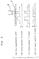
- These divided light fluxes are respectively incident upon the photo-detectors 10 and 11 so as to be converted into electrical signals, and are taken out as signals in opposite phases e.g. a signals S1 shown in Fig. 2(b) and a signal S2 shown in Fig. 2(c), according to the direction of magnetization on the disc 7 as illustrated in Fig. 2(a).
- These signals S1 and S2 are outputted as signals amplified two times as they are inputted to the differential amplifier 12, and applied to the divider 14.
- part of the light emitted by the semi-conductor laser source 1 is reflected by the beam splitter 4 so as to be incident upon the photo-detector 13.
- the light incident upon the photo-detector 13 is converted into an electrical signal, and is supplied to the divider 14 as a light intensity signal A proportional to the intensity of light from the semi-conductor laser source 1.
- this light intensity signal A is a denominator input, division of the above signals S1 and S2 is effected.
- the output signal S0 of the divider 14 is adjusted to the waveform of a full wave rectification by the full wave rectifier 15 and is taken out as a signal B to be judged as shown in Fig. 2(d).
- This signal B to be judged is compared with the preliminarily set threshold value V0 similarly shown in Fig. 2(d) by the comparator 16, thereby to check whether or not the recording function has been positively effected, with the recording bit at the disc 7 having reached Curie temperature.
- the focused light spot having comparatively large energy is projected onto the recording medium portion of the disc 7, with the state of magnetization at the recording medium portion having disappeared. Therefore, at the time point where the focused light spot is projected, no magneto-optical effect takes place. Accordingly, the signals S1 and S2 come to be in the same level in their absolute values, and the output signal of the differential amplifier 12, the output signal S0 of the divider 14 and the signal B to be judged of the output of the full wave rectifier 15 become zero respectively.
- the output signal of the differential amplifier 12, the output signal S0 of the divider 14, and the signal B to be judged, for the output of the full wave rectifier 15 as obtained from the reflection light at said portion show predetermined values. Therefore, by comparing the signal B to be judged with the threshold value V0 at the comparator 16, it is possible to judge whether or not the recording is normally effected. In Fig. 2(d), the portion lower than the threshold value V0 is the portion recorded.
- the output signal of the photo-detector 13 is used for the denominator input of the divider 14, in the case where the semi-conductor laser source 1 is made, for example, by a laser diode, the output signal of a photo-diode for output monitoring, incorporated in the laser diode may be utilized for the purpose. Similarly, it may be so modified to use the sum signal of the output signals S1 and S2 of the photo-detectors 10 and 11, or to omit the divider 14.
- the optical information recording and reproducing apparatus includes the light emitting means, the focusing means for collecting light emitted from said light emitting means onto the magneto-optical recording medium for raising temperature at the recording portion of said magneto-optical recording medium above Curie temperature so as to magnetize the recording portion in the direction of external magnetic field, thereby to effect recording of information, the analyzing means for separating the light reflected from the magneto-optical recording medium into polarization components in two directions corresponding to magnetizing direction in the magneto-optical recording medium, corresponding photo-detecting means for converting the separated light components into electrical signals so as to obtain reproduction signal from the information signal thus obtained, and subtracting means for subtracting the information signal obtained by the respective photo-detecting means during recording function.
- the optical information recording and reproducing apparatus is characterized in that there are further provided the waveform shaping means for adjusting the waveform of output signal from said subtracting means, and the comparing means for comparing the output signal of said waveform shaping means with the prelimiarily set threshold value.
- recording errors may be detected simultaneously with the recording function, without inviting complication in the construction and size increase of the optical system, and also, without requiring particular high accuracy in the optical system, and thus, reduction of recording time can be advantageously achieved.
Claims (6)
- Appareil d'enregistrement et de reproduction d'information optique comprenant une source lumineuse (1), un moyen pour orienter la lumière provenant de ladite source lumineuse (1) sur un milieu d'enregistrement magnéto-optique (7), pour permettre l'enregistrement d'une information par la variation sélective de l'état d'aimantation sur le milieu, un moyen d'analyse (9) pour diviser une lumière réfléchie par le milieu (7) durant l'enregistrement, en différentes composantes de polarisation, un moyen de photodétection (10, 11) pour produire des signaux électriques respectifs, représentant lesdites composantes de polarisation divisées et un moyen de soustraction (12) pour soustraire lesdits signaux électriques respectifs les uns des autres, caractérisé par un moyen de formation de forme d'onde, comprenant un redresseur pleine onde (15) pour ajuster la forme d'onde de sortie dudit moyen de soustraction (15) et un moyen de comparaison (16) pour comparer le signal de sortie dudit moyen de formation de forme d'onde (14, 15) avec une valeur de seuil déterminée au préalable.
- Appareil d'enregistrement et de reproduction d'information optique selon la revendication 1, dans lequel ledit moyen d'émission lumineuse (1) est une source laser à semiconducteur.
- Appareil d'enregistrement et de reproduction d'information optique selon la revendication 1, dans lequel ledit moyen de focalisation (6) est une lentille d'objectif.
- Appareil d'enregistrement et de reproduction d'information optique selon la revendication 1, dans lequel ledit moyen d'analyse (9) est un diviseur de faisceau polarisant.
- Appareil d'enregistrement et de reproduction d'information optique selon la revendication 1, dans lequel ledit moyen de photodétection (10, 11) est constitué de photodétecteurs.
- Appareil d'enregistrement et de reproduction d'information optique selon la revendication 1, dans lequel ledit moyen de soustraction (12) est un amplificateur différentiel.
Applications Claiming Priority (2)
| Application Number | Priority Date | Filing Date | Title |
|---|---|---|---|
| JP23675687 | 1987-09-21 | ||
| JP236756/87 | 1987-09-21 |
Publications (3)
| Publication Number | Publication Date |
|---|---|
| EP0309232A2 EP0309232A2 (fr) | 1989-03-29 |
| EP0309232A3 EP0309232A3 (en) | 1990-07-04 |
| EP0309232B1 true EP0309232B1 (fr) | 1994-01-19 |
Family
ID=17005324
Family Applications (1)
| Application Number | Title | Priority Date | Filing Date |
|---|---|---|---|
| EP88308773A Expired - Lifetime EP0309232B1 (fr) | 1987-09-21 | 1988-09-21 | Appareil d'enregistrement et de reproduction d'information optique |
Country Status (5)
| Country | Link |
|---|---|
| US (1) | US4985880A (fr) |
| EP (1) | EP0309232B1 (fr) |
| JP (1) | JPH01165056A (fr) |
| CA (1) | CA1316595C (fr) |
| DE (1) | DE3887242T2 (fr) |
Families Citing this family (12)
| Publication number | Priority date | Publication date | Assignee | Title |
|---|---|---|---|---|
| NL8901588A (nl) * | 1989-06-23 | 1991-01-16 | Philips Nv | Inrichting voor het optekenen van informatie op een registratiedrager met een stralingsgevoelige laag. |
| JP2706128B2 (ja) * | 1989-02-28 | 1998-01-28 | オリンパス光学工業株式会社 | 光磁気再生装置 |
| JPH0322235A (ja) * | 1989-06-19 | 1991-01-30 | Victor Co Of Japan Ltd | 光磁気ディスク記録再生装置 |
| CA2026740C (fr) * | 1989-11-20 | 1995-08-29 | Morovat Tayefeh | Lecture de l'information enregistree anterieurement durant l'enregistrement ou l'effacement d'un support magneto-optique |
| JP2798185B2 (ja) * | 1990-07-26 | 1998-09-17 | キヤノン株式会社 | 光磁気式情報再生装置用光学ヘッド |
| EP0818783A3 (fr) * | 1991-07-16 | 1999-04-14 | Canon Kabushiki Kaisha | Milieu d'enregistrement magnétooptique et méthode |
| JPH05144114A (ja) * | 1991-11-19 | 1993-06-11 | Canon Inc | 光磁気記録装置 |
| US5334849A (en) * | 1992-06-10 | 1994-08-02 | Iomega Corporation | Apparatus for and method of verifying etching of optical servo information on magnetic media |
| EP0673030A4 (fr) * | 1993-10-06 | 1996-02-21 | Nippon Kogaku Kk | Dispositif d'enregistrement sur disque optique. |
| US5495466A (en) * | 1994-01-10 | 1996-02-27 | Eastman Kodak Company | Write verification in an optical recording system by sensing mark formation while writing |
| JPH07262636A (ja) * | 1994-03-17 | 1995-10-13 | Pioneer Electron Corp | 光記録媒体再生装置 |
| DE19859035A1 (de) * | 1998-12-21 | 2000-06-29 | Thomson Brandt Gmbh | Gerät zum Lesen oder Schreiben optischer Aufzeichnungsträger mit unterschiedlichen Informationsträgerschichten |
Family Cites Families (3)
| Publication number | Priority date | Publication date | Assignee | Title |
|---|---|---|---|---|
| US3731290A (en) * | 1971-07-15 | 1973-05-01 | Honeywell Inc | Optical mass memory |
| JPS58203646A (ja) * | 1982-05-21 | 1983-11-28 | Canon Inc | 光磁気再生装置 |
| US4689779A (en) * | 1984-12-19 | 1987-08-25 | Kabushiki Kaisha Toshiba | Tracking control system for optical record disc information reproducing apparatus |
-
1988
- 1988-09-16 JP JP63232791A patent/JPH01165056A/ja active Pending
- 1988-09-20 CA CA000577959A patent/CA1316595C/fr not_active Expired - Lifetime
- 1988-09-21 DE DE3887242T patent/DE3887242T2/de not_active Expired - Fee Related
- 1988-09-21 EP EP88308773A patent/EP0309232B1/fr not_active Expired - Lifetime
- 1988-09-21 US US07/247,355 patent/US4985880A/en not_active Expired - Lifetime
Also Published As
| Publication number | Publication date |
|---|---|
| DE3887242T2 (de) | 1994-07-07 |
| EP0309232A3 (en) | 1990-07-04 |
| CA1316595C (fr) | 1993-04-20 |
| EP0309232A2 (fr) | 1989-03-29 |
| DE3887242D1 (de) | 1994-03-03 |
| JPH01165056A (ja) | 1989-06-29 |
| US4985880A (en) | 1991-01-15 |
Similar Documents
| Publication | Publication Date | Title |
|---|---|---|
| US4451863A (en) | Information reproducing apparatus based on opto-magnetic effect | |
| US4682311A (en) | Photomagnetic differential reproducing system | |
| US5488598A (en) | Optical pickup using split beams impinging on different photodetector areas | |
| EP0309232B1 (fr) | Appareil d'enregistrement et de reproduction d'information optique | |
| EP0289304B1 (fr) | Dispositif de contrôle de rayon utilisé dans une mémoire optique | |
| JPH01143044A (ja) | 情報再生装置 | |
| US4569035A (en) | Magneto-optical information reading apparatus | |
| EP0264285A2 (fr) | Appareil de reproduction d'information magnéto-optique | |
| US5004326A (en) | Magneto-optical information reproducing apparatus having a polarizing beam splitter disposed with an inclination of 45 degrees | |
| US5557601A (en) | Optical information recording/reproducing method and apparatus in which a first optical spot performs focusing, tracking, erasing and recording and a second optical spot performs two reproducing modes | |
| EP0238055A2 (fr) | Appareil d'enregistrement optique | |
| US4964110A (en) | Apparatus for reproducing a magneto-optical disk using a shot noise reduction circuit | |
| JPH0520725A (ja) | 光ピツクアツプ装置 | |
| EP0446021B1 (fr) | Dispositif de reproduction optique pour un milieu d'enregistrement magnéto-optique | |
| CA1312671C (fr) | Dispositif de reconnaissance de face de disque magneto-optique | |
| JPS5829155A (ja) | 光磁気方式による情報再生装置 | |
| US6097689A (en) | Optical pickup system incorporated therein a polarizing film and a pair of 1/4 wavelength plates | |
| JP2570743B2 (ja) | 光磁気記録媒体再生装置 | |
| JPS5877048A (ja) | 光磁気記録再生方式における読取装置 | |
| JP2862024B2 (ja) | 光磁気信号再生装置 | |
| KR960000270B1 (ko) | 광자기 디스크의 광픽업 장치 | |
| JP2574915B2 (ja) | 光磁気記録媒体の再生用光学装置 | |
| JPH03283112A (ja) | 光学ピックアップ装置 | |
| JPS6095737A (ja) | ノイズ除去方法 | |
| JPH06150358A (ja) | マルチビーム光ピックアップの光量検出装置 |
Legal Events
| Date | Code | Title | Description |
|---|---|---|---|
| PUAI | Public reference made under article 153(3) epc to a published international application that has entered the european phase |
Free format text: ORIGINAL CODE: 0009012 |
|
| 17P | Request for examination filed |
Effective date: 19881014 |
|
| AK | Designated contracting states |
Kind code of ref document: A2 Designated state(s): DE FR GB IT NL |
|
| PUAL | Search report despatched |
Free format text: ORIGINAL CODE: 0009013 |
|
| AK | Designated contracting states |
Kind code of ref document: A3 Designated state(s): DE FR GB IT NL |
|
| 17Q | First examination report despatched |
Effective date: 19911004 |
|
| GRAA | (expected) grant |
Free format text: ORIGINAL CODE: 0009210 |
|
| AK | Designated contracting states |
Kind code of ref document: B1 Designated state(s): DE FR GB IT NL |
|
| ITF | It: translation for a ep patent filed | ||
| REF | Corresponds to: |
Ref document number: 3887242 Country of ref document: DE Date of ref document: 19940303 |
|
| ET | Fr: translation filed | ||
| PLBE | No opposition filed within time limit |
Free format text: ORIGINAL CODE: 0009261 |
|
| STAA | Information on the status of an ep patent application or granted ep patent |
Free format text: STATUS: NO OPPOSITION FILED WITHIN TIME LIMIT |
|
| 26N | No opposition filed | ||
| REG | Reference to a national code |
Ref country code: GB Ref legal event code: IF02 |
|
| PGFP | Annual fee paid to national office [announced via postgrant information from national office to epo] |
Ref country code: NL Payment date: 20040905 Year of fee payment: 17 |
|
| PGFP | Annual fee paid to national office [announced via postgrant information from national office to epo] |
Ref country code: GB Payment date: 20040915 Year of fee payment: 17 |
|
| PGFP | Annual fee paid to national office [announced via postgrant information from national office to epo] |
Ref country code: DE Payment date: 20040916 Year of fee payment: 17 |
|
| PG25 | Lapsed in a contracting state [announced via postgrant information from national office to epo] |
Ref country code: GB Free format text: LAPSE BECAUSE OF NON-PAYMENT OF DUE FEES Effective date: 20050921 Ref country code: IT Free format text: LAPSE BECAUSE OF NON-PAYMENT OF DUE FEES Effective date: 20050921 |
|
| PG25 | Lapsed in a contracting state [announced via postgrant information from national office to epo] |
Ref country code: NL Free format text: LAPSE BECAUSE OF NON-PAYMENT OF DUE FEES Effective date: 20060401 Ref country code: DE Free format text: LAPSE BECAUSE OF NON-PAYMENT OF DUE FEES Effective date: 20060401 |
|
| GBPC | Gb: european patent ceased through non-payment of renewal fee |
Effective date: 20050921 |
|
| NLV4 | Nl: lapsed or anulled due to non-payment of the annual fee |
Effective date: 20060401 |
|
| PGFP | Annual fee paid to national office [announced via postgrant information from national office to epo] |
Ref country code: FR Payment date: 20070914 Year of fee payment: 20 |