EP0309251B1 - Estimateur de mouvement - Google Patents
Estimateur de mouvement Download PDFInfo
- Publication number
- EP0309251B1 EP0309251B1 EP88308819A EP88308819A EP0309251B1 EP 0309251 B1 EP0309251 B1 EP 0309251B1 EP 88308819 A EP88308819 A EP 88308819A EP 88308819 A EP88308819 A EP 88308819A EP 0309251 B1 EP0309251 B1 EP 0309251B1
- Authority
- EP
- European Patent Office
- Prior art keywords
- frame
- block
- regions
- region
- picture elements
- Prior art date
- Legal status (The legal status is an assumption and is not a legal conclusion. Google has not performed a legal analysis and makes no representation as to the accuracy of the status listed.)
- Expired - Lifetime
Links
Images



Classifications
-
- H—ELECTRICITY
- H04—ELECTRIC COMMUNICATION TECHNIQUE
- H04N—PICTORIAL COMMUNICATION, e.g. TELEVISION
- H04N19/00—Methods or arrangements for coding, decoding, compressing or decompressing digital video signals
- H04N19/42—Methods or arrangements for coding, decoding, compressing or decompressing digital video signals characterised by implementation details or hardware specially adapted for video compression or decompression, e.g. dedicated software implementation
- H04N19/43—Hardware specially adapted for motion estimation or compensation
-
- G—PHYSICS
- G06—COMPUTING OR CALCULATING; COUNTING
- G06T—IMAGE DATA PROCESSING OR GENERATION, IN GENERAL
- G06T7/00—Image analysis
- G06T7/20—Analysis of motion
- G06T7/223—Analysis of motion using block-matching
- G06T7/231—Analysis of motion using block-matching using full search
-
- H—ELECTRICITY
- H04—ELECTRIC COMMUNICATION TECHNIQUE
- H04N—PICTORIAL COMMUNICATION, e.g. TELEVISION
- H04N19/00—Methods or arrangements for coding, decoding, compressing or decompressing digital video signals
- H04N19/50—Methods or arrangements for coding, decoding, compressing or decompressing digital video signals using predictive coding
- H04N19/503—Methods or arrangements for coding, decoding, compressing or decompressing digital video signals using predictive coding involving temporal prediction
- H04N19/51—Motion estimation or motion compensation
Definitions
- the present invention concerns motion estimation, particularly, though not exclusively, in the context of video coders employing inter-frame differential coding.
- Figure 1 shows a known form of video coder.
- Video signals (commonly in digital form) are received at an input 1.
- a subtractor 2 forms the difference between the input and a predicted signal from a predictor 3 which is then further coded in box 4.
- the coding performed here is not material to the present invention, but may include thresholding (to suppress transmission of zero or minor differences) quantisation or transform coding for example.
- the input to the predictor is the sum, formed in an adder 5 of the prediction and the coded difference signal decoded in a local decoder 6 (so that loss of information in the coding and decoding process is included in the predictor loop).
- the differential coding is essentially inter-frame, and the predictor 3 could simply consist of a one-frame delay; as shown however a motion estimator 7 is also included.
- This compares the frame of the picture being coded with the previous frame being supplied to the predictor. For each block of the current frame (into which the picture is regarded as divided) it identifies that region of the previous frame which the block most closely resembles.
- the vector difference in position between the identified region and the block in question is termed a motion vector (since it usually represents motion of an object within the scene depicted by the television picture) and is applied to the predictor to shift the identified region of the previous frame into the position of the relevant block in the current frame, thereby making the predictor output a better prediction.
- This results in the differences formed by the subtracter 2 being, on average, smaller and permits the coder 4 to encode the picture using a lower bit rate than would otherwise be the case.
- the motion estimator must typically compare each block with the corresponding block of the previous frame and regions positionally shifted from that block position; this involves a considerable amount of processing and often necessitates many accesses to stored versions of both frames.
- a motion detector for video signals comprises: means for the reception and temporary storage of video signals representing one frame of a picture and another frame of a picture in which each frame is formed from a plurality of lines and the one frame is constituted by a plurality of non-overlapping rows of blocks, each of the rows being constituted by a plurality of non-overlapping blocks of picture elements formed from respective portions of a respective set of frame lines; arithmetic means arranged to compare each of the blocks of the one frame with a corresponding region of the other frame and with a plurality of positionally shifted regions of the other frame which represent a desired two-dimensional search extent; and first means responsive to the results of the comparisons to produce vector information indicating a positional shift, if any, of the position of a region of the other frame to the position of a block in the one frame which meets a criterion of similarity, the set of vector information so produced constituting the estimation of the motion between the frames; CHARACTERISED IN THAT the motion detector includes:
- the motion estimator to be described regards a "current" frame of a television picture which is being coded as being divided into 8 x 8 blocks - that is, eight picture elements (pixels) horizontally by eight lines vertically. Although the principles are equally applicable to interlaced systems, for simplicity of description a non-interlaced picture is assumed. It is designed to generate for each block a motion vector which indicates the position of the 8 x 8 region, lying within a defined search area of the (or a) previous frame of the picture, which is most similar to the block in question.
- Figure 2 illustrates a field with an 8 x 8 block N (shaded) and a typical associated 23 x 23 search area indicated by a rectangle S N .
- the search area for a block whose upper left hand corner pixel has coordinates x N ,y N is the area extending horizontally from (x N -8) to (x N +14) and vertically from (y N -8) to (y N +14).
- the motion vector is the values of u,v for which the comparison indicates the greatest similarity.
- the test for similarity can be any conventionally used - e.g. the sum of the absolute values of the differences between each of the pixels in the "current" block and the relevant region of the previous frame.
- the search is carried out for each block of the current picture in turn.
- the search area associated with a block overlaps the search areas of a number (24 in the case of blocks not close to the edge of the picture) of other blocks this (see the search area shown dotted in Fig 2 for block N+1) often requires multiple accesses to the previous frame information stored in a frame store, which are time consuming and may interfere with other coder functions.
- the motion estimator to be described is assumed to be provided, in real time, with
- the signals consist of a sequence of 8-bit digital words representing the luminance of successive picture elements of the first line, (though chrominance signals could be similarly processed if desired) followed by similar sequences for the second, third and subsequent lines.
- the apparatus is arranged so that all comparisons involving a particular line of the picture are carried out consecutively. As will be seen, this requires a storage capacity of only a total of sixteen line delays for the previous frame.
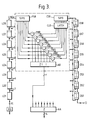
- Figure 3 shows part of the apparatus, the operation of which will be described with reference to figure 4.
- the "position" in the picture of an 8 x 8 block or region will be considered as defined by the x,y coordinates of its upper left pixel.
- the block N in figure 4 is at position x,y.
- the apparatus of figure 2 serves to compare the 8 x 8 block N at x,y with the 8 x 8 regions at (x+u),(y+v) where u ranges from -8 to +7 and v from 0 to +7 - ie the regions whose positions are within the lower broken line area S1 in figure 4.
- the previous frame is received (following a 9-pixel delay XD, the purpose of which will be apparent later) at an input PI (all signal paths in the figure are 8-bit unless otherwise indicated by a diagonal bar and adjacent number).
- This supplies a tapped delay line consisting of eight one-line delay units LD1...LD8, so that the signal for any line of the picture is available at the output of LD8 and that for the seven later lines is available at the outputs of LD7, LD6 etc.
- the current picture signal is supplied via input CI to a delay line with storage having eight sections DS1... DS8. Each section consists of two delay units of one line period duration; one half of each section forms part of an eight line period delay line and the other half forms a recirculating store.
- the outputs of LD8 and DS8 feed respective (8-bit wide) 8-stage serial in parallel out (SIPO) registers PS8, CS8 clocked at pixel rate.
- the eight outputs of the latter are latched in a latch CL8 every 16 pixels synchronously with the horizontal block structure of the frame.
- pixels x to (x+7) are available at the output of latch CL8 on the next clock pulse.
- pixels x-8 to x-1 are available at the outputs of the SIPO PS8 (due to the 9-pixel delay XD).
- the outputs of the PS8 and CL8 are supplied to subtractors M81 - M88; the sum of the moduli of the differences is formed in a summation unit A8.
- the summer output represents the "sum of differences" between the first line of the current picture block N, and the first line of the region indicated by chain-dot lines in figure 4.
- the arrangement consisting of PS8,CS8, CL8, M81-88 and A8 is provided for the outputs of LD8 and DS8; seven further such arrangements are provided (though, for clarity, not shown in Figure 3) for the outputs of LD7/DS7, LD6/DS6...LD1/DS1. They function in an identical manner, except that, being connected to earlier taps of the delay lines, they operate on the seven later lines of the picture.
- the outputs of the summers A8....A1 are added in an adder AA which produces the "sum of differences" between the current block N and the 8 x 8 region of the previous frame indicated by the chain-dot lines in figure 4. This is the value E x,y (-8,0) according to the definition given above.
- next-but-one block N+2 of the current frame i.e. those with horizontal co-ordinates (x+16) to (x+23)
- these are clocked into the latches CL8..., at which point pixels (x+8) to (x+15) are available at PS8, corresponding to search position for the new block, and the first pass now proceeds for block N+2, and successive alternate blocks until the end of the line.
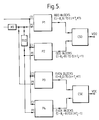
- FIG. 5 the arrangements of figure 3 (apart from delay XD) now appear as processor P1.
- a second processor P2 handles the upper search area S2; it is identical in all respects to P1 but is supplied with the previous frame signal via an 8 line delay (shown explicitly as ELD though in practice the signal could be tapped from LD8 of the processor P1), giving the desired result of defining a search area S2 which is 8 lines earlier than S1. It is noted in passing that were the search S N area smaller (i.e. 17x17 or less rather than 23x23) one processor (suitably timed) would suffice.
- processors P3, P4 which are identical to P1 and P2 and receive the same signal inputs as P1 and P2 respectively.
- latches CL8 are clocked (every 16 pixels as before) with pulses which are 8 pixels out of phase with those supplied to the processors P1 and P2.
- the figure shows identical processors (which may be a convenient modular hardware implementation), certain of the elements within the processors may if desired be common to two or more of the processors, (e.g. the lines DS8....DS1).
- Unit CSO is shown in Figure 6 and is identical to CSE (except for the timing of the inputs, of course).
- a vector generator VG synchronised by pixel clock (and line and field synchronising pulses) produces the value of the vector component u (4 bits) and the lower 3 bits of component v associated with the E value being received from the processor P1.
- the two E values received simultaneously from P1 and P2 always relate to the same block of the current picture, so that these can readily be compared by a comparator C1.
- the comparator output controls a data selector SEL1 to output the smaller of the received values; the comparator output also is appended to the vector generator output to form the most insignificant bit of v.
- a border detector BG serves to override the action of the selector SEL1 by:
- a first-in-first-out store FIFO1 stores the lowest E value for each odd block of a row. All the store locations are set to their maximum value at the commencement of a row.
- Each processor pass generates, for any block N, sixteen E values in succession.
- a comparator C2 compares it with the previous value recorded in the store for the relevant block and controls the selector SEL2 to enter into a latch whichever is the lower of the two values.
- a second selector SEL3 then switches to feed the latch output to the comparator C2 (and selector SEL1) and the comparator compares each of the remaining fifteen values with the value held in the latch L1; again, the selector SEL1 passes the lower value of the pair to form the new latched value. After the sixteen values have been compared, the content of the latch is loaded back into the store.
- selectors SEL4, SEL5 and latch L2 select for entry into a second store FIF02 either the vector previously stored therein or the incoming vector (from VG and C1).
- the store FIF01 contains the lowest "sum of differences" value E for each block of the row, and the store FIF02 contains the corresponding vectors u,v. These can then be read out and output to the output VOO prior to the processing of the next row.
- a vector mapping unit VM - which may be a simple look-up table - can be included.
- the previous frame region to be identified is the one having the smallest difference from the current block in question.
- a bias to the zero vector - i.e. a non-zero vector is output only if a region u,v gives a sum of differences E(u,v) which is less by a predetermined amount than the value E (0,0) for the undisplaced region of the previous frame - e.g. is less than 75% of E(0,0).
- This can be achieved by a scaling unit ZVS which normally passes the valves received from the processor P1 unchanged, but reduces the value to 75% of the input valve when a signal VO from the vector generator VG indicates a position (0,0).
Landscapes
- Engineering & Computer Science (AREA)
- Multimedia (AREA)
- Signal Processing (AREA)
- Computer Vision & Pattern Recognition (AREA)
- Physics & Mathematics (AREA)
- General Physics & Mathematics (AREA)
- Theoretical Computer Science (AREA)
- Compression Or Coding Systems Of Tv Signals (AREA)
- Retarders (AREA)
- Dry Shavers And Clippers (AREA)
- Optical Communication System (AREA)
- Saccharide Compounds (AREA)
- Manipulator (AREA)
- Apparatus For Radiation Diagnosis (AREA)
- Magnetic Resonance Imaging Apparatus (AREA)
- Burglar Alarm Systems (AREA)
- Cephalosporin Compounds (AREA)
- Pharmaceuticals Containing Other Organic And Inorganic Compounds (AREA)
- Measuring Pulse, Heart Rate, Blood Pressure Or Blood Flow (AREA)
- Detergent Compositions (AREA)
- Organic Low-Molecular-Weight Compounds And Preparation Thereof (AREA)
Claims (6)
- Détecteur de mouvement pour signaux vidéo, comprenant :
des moyens (DS, CS, CL, LD, PS) de réception et d'enregistrement temporaire de signaux vidéo représentant une trame d'une image, et une autre trame d'une image dans laquelle chaque trame est formée à partir d'une pluralité de lignes et la trame en question est constituée par une pluralité de rangées de blocs ne se chevauchant pas, chacune de ces rangées étant constituée par une pluralité de blocs ne se chevauchant pas d'éléments d'images formés à partir de portions respectives d'un jeu respectif de lignes de trame ;
des moyens arithmétiques (M, A et AA de P1 et P3) disposés de manière à comparer chacun des blocs de la trame en question avec une région correspondante de l'autre trame, et avec une pluralité de régions décalées de l'autre trame, qui représentent un domaine de recherche désirée à deux dimensions (SI) ;
un des premiers moyens coopérant avec les résultats des comparaisons, de manière à produire des informations vectorielles (VOO, VOE) indiquant le cas échéant un décalage de position entre la position d'une région de l'autre trame, et la position d'un bloc dans la trame qui remplit un critère de similitude, le jeu d'information vectoriel ainsi produit constituant l'estimation du mouvement entre les trames ; caractérisé en ce que le détecteur de mouvement inclut :(i) des moyens de retardement (LD, PS) disposés :(a) pour rendre disponibles, tour à tour des régions d'éléments d'images selon une séquence prédéterminée de régions d'éléments d'images, chaque région correspondant à une région de l'autre trame de même taille que le bloc de la première trame, des régions successives à l'intérieur de la séquence de région correspondant à des régions déplacées progressivement horizontalement dans une direction le long des lignes de l'autre trame, tous les éléments d'image d'une région étant rendus disponibles simultanément ; et(b) pour répéter l'étape (a) pour des séquences successives de régions correspondant aux régions progressivement déplacées perpendiculairement à la direction le long des lignes de l'autre trame jusqu'à un domaine correspondant au domaine désire de recherche (SI), verticalement,(ii) des moyens de retardement et d'enregistrement (DS, OS, CL) disposés(c) pour rendre disponibles à tour de rôle des blocs d'éléments d'images selon une séquence prédéterminée à partir d'une rangée de blocs, tous les éléments d'image d'un bloc étant rendus disponibles simultanément et durant une période correspondant au domaine désiré de recherche (SI) horizontalement, dans la direction des lignes de l'image ; et(d) pour répéter la séquence prédéterminée autant de fois qu'il y a de séquences successives de régions déplacées dans la direction verticale à l'étape (b) ;et en ce que :(iii) les moyens arithmétiques (M, A et AA) sont disposés de manière à former la somme des modules ou de tout autre fonction paire croissante monotone, des différences entre les éléments d'images rendus disponibles pour un bloc, et les éléments d'images rendus disponibles pour une région ; et(iv) les premiers moyens (CSO, CSE) sont disposés en opération pour établir pour chaque bloc, les informations vectorielles correspondant à la région dont la somme remplit ledit critère. - Détecteur selon la revendication 1, dans lequel le domaine désiré de recherche (SI) horizontalement dans la direction des lignes, est plus grand ou égal au double du domaine d'un bloc dans cette direction, les moyens de retardement et d'enregistrement sont disposés simultanément de manière à former une pluralité q (où q est un entier plus grand que 1) de séquences différentes contenant des groupes d'éléments d'images correspondant à chaque q-ième bloc dans la direction des lignes, et les moyens arithmétiques comprennent une pluralité q d'arrangements permettant la formation desdites sommes pour les séquences respectives.
- Détecteur selon l'une des revendications 1 ou 2, dans lequel les moyens de retardement et d'enregistrement sont disposés simultanément afin de rendre disponible une séquence additionnelle correspondant aux régions (ou blocs) déplacées par le nombre prédéterminé des lignes relatives à la séquence premièrement mentionnée, le détecteur inclut des moyens arithmétiques additionnels (M, A et AA de P2 et P4) coopérant avec la séquence additionnelle, afin de comparer chaque bloc de ladite première trame avec une autre pluralité de région déplacée de ladite autre trame qui représentent une extension (S2) dudit domaine de recherche, et les moyens (CSO, CSE) de production des informations vectorielles sont reliées de manière à recevoir les sommes provenant à la fois des moyens arithmétiques premièrement mentionnés (dans P1, P3) et des moyens arithmétiques additionnels (dans P2, P4).
- Détecteur selon l'une quelconque des revendications précédentes, dans lequel les premiers moyens comprennent des moyens (C1, C2) de comparaison des valeurs sorties par les moyens arithmétiques à partir d'un bloc, avec celle des valeurs précédentes de ce bloc qui remplit le critère, et incluent des moyens (FIFO1) d'enregistrement intermédiaire des résultats partiels durant les comparaisons de valeur pour les autres blocs.
- Détecteur selon la revendication 4, dans lequel les premiers moyens incluent des moyens (VG) générant des valeurs vectorielles correspondant aux régions représentées par les valeurs sorties par les moyens arithmétiques, des moyens de commutation (SEL4, L2, SEL5) pour sélectionner la valeur vectorielle correspondant à la dernière région remplissant le critère, et des moyens (FIFO2) d'enregistrement intermédiaire des valeurs vectorielles correspondant auxdits résultats partiels enregistrés de manière intermédiaire.
- Détecteur selon l'une quelconque des revendications précédentes, caractérisé en ce que ledit critère est rempli par une région pour laquelle une valeur de comparaison égale dans le cas de région non déplacée, à une proportion prédéterminée de ladite somme, et égale dans le cas des autres régions, à ladite somme, est inférieure à la valeur de comparaison pour toutes les autres régions par rapport au bloc.
Priority Applications (1)
| Application Number | Priority Date | Filing Date | Title |
|---|---|---|---|
| AT88308819T ATE97534T1 (de) | 1987-09-25 | 1988-09-22 | Bewegungsabschaetzung. |
Applications Claiming Priority (2)
| Application Number | Priority Date | Filing Date | Title |
|---|---|---|---|
| GB8722612 | 1987-09-25 | ||
| GB878722612A GB8722612D0 (en) | 1987-09-25 | 1987-09-25 | Motion estimator |
Publications (2)
| Publication Number | Publication Date |
|---|---|
| EP0309251A1 EP0309251A1 (fr) | 1989-03-29 |
| EP0309251B1 true EP0309251B1 (fr) | 1993-11-18 |
Family
ID=10624380
Family Applications (1)
| Application Number | Title | Priority Date | Filing Date |
|---|---|---|---|
| EP88308819A Expired - Lifetime EP0309251B1 (fr) | 1987-09-25 | 1988-09-22 | Estimateur de mouvement |
Country Status (13)
| Country | Link |
|---|---|
| US (1) | US5083202A (fr) |
| EP (1) | EP0309251B1 (fr) |
| JP (1) | JP3009674B2 (fr) |
| AT (1) | ATE97534T1 (fr) |
| AU (1) | AU609536B2 (fr) |
| CA (1) | CA1318970C (fr) |
| DE (1) | DE3885695T2 (fr) |
| DK (1) | DK76990D0 (fr) |
| FI (1) | FI96563C (fr) |
| GB (2) | GB8722612D0 (fr) |
| HK (2) | HK135796A (fr) |
| IE (1) | IE61586B1 (fr) |
| WO (1) | WO1989003152A1 (fr) |
Cited By (7)
| Publication number | Priority date | Publication date | Assignee | Title |
|---|---|---|---|---|
| WO1989008891A1 (fr) * | 1988-03-14 | 1989-09-21 | Bell Communications Research, Inc. | Circuit de mise en oeuvre d'algorithme de correspondance de bloc |
| EP0395293A1 (fr) * | 1989-04-26 | 1990-10-31 | BRITISH TELECOMMUNICATIONS public limited company | Estimateur de mouvement |
| EP0395271A3 (fr) * | 1989-04-27 | 1992-01-08 | Sony Corporation | Traitement de signal vidéo dépendant du mouvement |
| EP0395272A3 (fr) * | 1989-04-27 | 1992-01-08 | Sony Corporation | Traitement de signal vidéo dépendant du mouvement |
| EP0395265A3 (fr) * | 1989-04-27 | 1992-01-22 | Sony Corporation | Traitement de signal vidéo dépendant du mouvement |
| US5400087A (en) * | 1992-07-06 | 1995-03-21 | Mitsubishi Denki Kabushiki Kaisha | Motion vector detecting device for compensating for movements in a motion picture |
| EP0848558A1 (fr) * | 1996-12-13 | 1998-06-17 | Fujitsu Limited | Dispositif de recherche de vecteurs de mouvement et codeur vidéo |
Families Citing this family (19)
| Publication number | Priority date | Publication date | Assignee | Title |
|---|---|---|---|---|
| US4963961A (en) * | 1989-06-16 | 1990-10-16 | Burle Technologies, Inc. | Vertical motion detector |
| WO1992005662A1 (fr) * | 1990-09-20 | 1992-04-02 | British Broadcasting Corporation | Traitement d'images video |
| US5210605A (en) * | 1991-06-11 | 1993-05-11 | Trustees Of Princeton University | Method and apparatus for determining motion vectors for image sequences |
| US6965644B2 (en) * | 1992-02-19 | 2005-11-15 | 8×8, Inc. | Programmable architecture and methods for motion estimation |
| US5461423A (en) * | 1992-05-29 | 1995-10-24 | Sony Corporation | Apparatus for generating a motion vector with half-pixel precision for use in compressing a digital motion picture signal |
| US5430886A (en) * | 1992-06-15 | 1995-07-04 | Furtek; Frederick C. | Method and apparatus for motion estimation |
| US5412435A (en) * | 1992-07-03 | 1995-05-02 | Kokusai Denshin Denwa Kabushiki Kaisha | Interlaced video signal motion compensation prediction system |
| KR0160618B1 (ko) * | 1992-10-27 | 1999-01-15 | 윤종용 | 실시간 움직임 추정장치 및 그 방법 |
| US5471248A (en) * | 1992-11-13 | 1995-11-28 | National Semiconductor Corporation | System for tile coding of moving images |
| JP2636674B2 (ja) * | 1993-05-25 | 1997-07-30 | 日本電気株式会社 | 動画像の動きベクトル検出装置 |
| GB9315775D0 (en) * | 1993-07-30 | 1993-09-15 | British Telecomm | Processing image data |
| US5396284A (en) * | 1993-08-20 | 1995-03-07 | Burle Technologies, Inc. | Motion detection system |
| US5398068A (en) * | 1993-09-02 | 1995-03-14 | Trustees Of Princeton University | Method and apparatus for determining motion vectors for image sequences |
| JPH07115646A (ja) * | 1993-10-20 | 1995-05-02 | Sony Corp | 画像処理装置 |
| FR2719398B1 (fr) * | 1994-04-27 | 1996-07-19 | Sgs Thomson Microelectronics | Dispositif et procédé d'adressage d'une mémoire cache d'un circuit de compression d'images mobiles. |
| US5537155A (en) * | 1994-04-29 | 1996-07-16 | Motorola, Inc. | Method for estimating motion in a video sequence |
| GB2320388B (en) * | 1996-11-29 | 1999-03-31 | Sony Corp | Image processing apparatus |
| GB2327827B (en) * | 1996-11-29 | 1999-06-30 | Sony Corp | Image processing apparatus |
| GB2360897A (en) * | 2000-03-31 | 2001-10-03 | Sony Uk Ltd | Video motion detection |
Family Cites Families (6)
| Publication number | Priority date | Publication date | Assignee | Title |
|---|---|---|---|---|
| JPS6075184A (ja) * | 1983-09-30 | 1985-04-27 | Nec Corp | 動画像信号の符号化方式とその装置 |
| US4670851A (en) * | 1984-01-09 | 1987-06-02 | Mitsubishi Denki Kabushiki Kaisha | Vector quantizer |
| JP2512894B2 (ja) * | 1985-11-05 | 1996-07-03 | ソニー株式会社 | 高能率符号化/復号装置 |
| DE3721074A1 (de) * | 1986-12-24 | 1988-07-07 | Licentia Gmbh | Schaltungsanordnung zur verschiebungsvektorsuche in der digitalen bildanalyse |
| EP0624985B1 (fr) * | 1987-04-28 | 2001-03-14 | Mitsubishi Denki Kabushiki Kaisha | Système pour le codage et le décodage d'images |
| US4897720A (en) * | 1988-03-14 | 1990-01-30 | Bell Communications Research, Inc. | Circuit implementation of block matching algorithm |
-
1987
- 1987-09-25 GB GB878722612A patent/GB8722612D0/en active Pending
-
1988
- 1988-09-22 CA CA000578199A patent/CA1318970C/fr not_active Expired - Lifetime
- 1988-09-22 EP EP88308819A patent/EP0309251B1/fr not_active Expired - Lifetime
- 1988-09-22 WO PCT/GB1988/000781 patent/WO1989003152A1/fr not_active Ceased
- 1988-09-22 AT AT88308819T patent/ATE97534T1/de not_active IP Right Cessation
- 1988-09-22 DE DE3885695T patent/DE3885695T2/de not_active Expired - Lifetime
- 1988-09-22 US US07/469,494 patent/US5083202A/en not_active Expired - Lifetime
- 1988-09-22 AU AU24843/88A patent/AU609536B2/en not_active Ceased
- 1988-09-22 JP JP63507635A patent/JP3009674B2/ja not_active Expired - Lifetime
- 1988-09-23 IE IE288688A patent/IE61586B1/en not_active IP Right Cessation
-
1990
- 1990-03-22 GB GB9006474A patent/GB2229603B/en not_active Expired - Lifetime
- 1990-03-23 FI FI901458A patent/FI96563C/fi not_active IP Right Cessation
- 1990-03-23 DK DK076990A patent/DK76990D0/da not_active Application Discontinuation
-
1996
- 1996-07-25 HK HK135796A patent/HK135796A/en not_active IP Right Cessation
- 1996-08-15 HK HK154596A patent/HK154596A/xx not_active IP Right Cessation
Cited By (13)
| Publication number | Priority date | Publication date | Assignee | Title |
|---|---|---|---|---|
| WO1989008891A1 (fr) * | 1988-03-14 | 1989-09-21 | Bell Communications Research, Inc. | Circuit de mise en oeuvre d'algorithme de correspondance de bloc |
| US4897720A (en) * | 1988-03-14 | 1990-01-30 | Bell Communications Research, Inc. | Circuit implementation of block matching algorithm |
| EP0395293A1 (fr) * | 1989-04-26 | 1990-10-31 | BRITISH TELECOMMUNICATIONS public limited company | Estimateur de mouvement |
| WO1990013205A1 (fr) * | 1989-04-26 | 1990-11-01 | British Telecommunications Public Limited Company | Estimateur de mouvement |
| US5206723A (en) * | 1989-04-26 | 1993-04-27 | British Telecommunications Public Limited Company | Motion estimator |
| AU626120B2 (en) * | 1989-04-26 | 1992-07-23 | British Telecommunications Public Limited Company | Motion estimator |
| EP0395265A3 (fr) * | 1989-04-27 | 1992-01-22 | Sony Corporation | Traitement de signal vidéo dépendant du mouvement |
| EP0395272A3 (fr) * | 1989-04-27 | 1992-01-08 | Sony Corporation | Traitement de signal vidéo dépendant du mouvement |
| EP0395271A3 (fr) * | 1989-04-27 | 1992-01-08 | Sony Corporation | Traitement de signal vidéo dépendant du mouvement |
| GB2231226B (en) * | 1989-04-27 | 1993-09-22 | Sony Corp | Motion dependent video signal processing |
| US5400087A (en) * | 1992-07-06 | 1995-03-21 | Mitsubishi Denki Kabushiki Kaisha | Motion vector detecting device for compensating for movements in a motion picture |
| EP0848558A1 (fr) * | 1996-12-13 | 1998-06-17 | Fujitsu Limited | Dispositif de recherche de vecteurs de mouvement et codeur vidéo |
| US6263112B1 (en) | 1996-12-13 | 2001-07-17 | Fujitsu Limited | Motion vector searching apparatus and motion picture coding apparatus |
Also Published As
| Publication number | Publication date |
|---|---|
| US5083202A (en) | 1992-01-21 |
| JP3009674B2 (ja) | 2000-02-14 |
| ATE97534T1 (de) | 1993-12-15 |
| JPH03502628A (ja) | 1991-06-13 |
| DK76990D0 (da) | 1990-03-23 |
| GB2229603A (en) | 1990-09-26 |
| IE882886L (en) | 1989-03-25 |
| DE3885695T2 (de) | 1994-06-23 |
| FI96563B (fi) | 1996-03-29 |
| WO1989003152A1 (fr) | 1989-04-06 |
| EP0309251A1 (fr) | 1989-03-29 |
| AU2484388A (en) | 1989-04-18 |
| CA1318970C (fr) | 1993-06-08 |
| HK154596A (en) | 1996-08-23 |
| AU609536B2 (en) | 1991-05-02 |
| GB8722612D0 (en) | 1987-11-04 |
| GB9006474D0 (en) | 1990-07-18 |
| DE3885695D1 (de) | 1993-12-23 |
| FI901458A0 (fi) | 1990-03-23 |
| HK135796A (en) | 1996-08-02 |
| GB2229603B (en) | 1991-08-14 |
| IE61586B1 (en) | 1994-11-16 |
| FI96563C (fi) | 1996-07-10 |
Similar Documents
| Publication | Publication Date | Title |
|---|---|---|
| EP0309251B1 (fr) | Estimateur de mouvement | |
| AU626120B2 (en) | Motion estimator | |
| US5210605A (en) | Method and apparatus for determining motion vectors for image sequences | |
| US5398068A (en) | Method and apparatus for determining motion vectors for image sequences | |
| EP0259562B1 (fr) | Procédé de codage à prédiction intertrame avec compensation du mouvement | |
| US4862267A (en) | Motion compensated interpolation of digital television images | |
| US5251028A (en) | Apparatus for reducing quantization artifacts in an interframe hybrid coding system with motion compensation | |
| JP2968838B2 (ja) | 画像列の動作を予測しかつ階層的コード化を行う方法及び装置 | |
| US6122317A (en) | Motion vector detector | |
| US4571618A (en) | TV Signal median prediction coding system | |
| JP3101691B2 (ja) | 二次元動画像の連続するピクセルを表わすデータ信号を処理するための方法および回路 | |
| EP0720386A2 (fr) | Circuit de codeur/décodeur à traitement temporellement en pipeline et méthode | |
| EP0585051A2 (fr) | Procédé et appareil de traitement d'images | |
| KR20010071705A (ko) | 디지털 비디오를 위한 이동 추정 방법 및 장치 | |
| JPH0192885A (ja) | デイジタル像シーケンスからの運動ベクトル場の探索方法 | |
| EP0577310B1 (fr) | Dispositif de traitement d'image | |
| US5469214A (en) | Device for recursive processing of a video signal, comprising a plurality of branches | |
| EP1420595B1 (fr) | Sélection de vecteurs de mouvement par rapport à un repère fixe dans un estimateur de mouvement d'un encodeur vidéo | |
| US6560286B1 (en) | Field frame motion design for digital video decoder | |
| IE901502A1 (en) | Motion estimator | |
| KR970003793B1 (ko) | 블록정합 동추정방법 및 장치 | |
| HK1014434B (en) | Motion estimator | |
| JPH06178289A (ja) | 動きベクトル検出回路 | |
| JPS62289080A (ja) | 画素補間装置 |
Legal Events
| Date | Code | Title | Description |
|---|---|---|---|
| PUAI | Public reference made under article 153(3) epc to a published international application that has entered the european phase |
Free format text: ORIGINAL CODE: 0009012 |
|
| AK | Designated contracting states |
Kind code of ref document: A1 Designated state(s): AT BE CH DE ES FR GB GR IT LI LU NL SE |
|
| 17P | Request for examination filed |
Effective date: 19890919 |
|
| 17Q | First examination report despatched |
Effective date: 19910917 |
|
| GRAA | (expected) grant |
Free format text: ORIGINAL CODE: 0009210 |
|
| AK | Designated contracting states |
Kind code of ref document: B1 Designated state(s): AT BE CH DE ES FR GB GR IT LI LU NL SE |
|
| PG25 | Lapsed in a contracting state [announced via postgrant information from national office to epo] |
Ref country code: ES Free format text: THE PATENT HAS BEEN ANNULLED BY A DECISION OF A NATIONAL AUTHORITY Effective date: 19931118 Ref country code: BE Effective date: 19931118 Ref country code: CH Effective date: 19931118 Ref country code: AT Effective date: 19931118 Ref country code: GR Free format text: LAPSE BECAUSE OF FAILURE TO SUBMIT A TRANSLATION OF THE DESCRIPTION OR TO PAY THE FEE WITHIN THE PRESCRIBED TIME-LIMIT Effective date: 19931118 Ref country code: LI Effective date: 19931118 |
|
| REF | Corresponds to: |
Ref document number: 97534 Country of ref document: AT Date of ref document: 19931215 Kind code of ref document: T |
|
| REF | Corresponds to: |
Ref document number: 3885695 Country of ref document: DE Date of ref document: 19931223 |
|
| ITF | It: translation for a ep patent filed | ||
| REG | Reference to a national code |
Ref country code: CH Ref legal event code: PL |
|
| ET | Fr: translation filed | ||
| PLBE | No opposition filed within time limit |
Free format text: ORIGINAL CODE: 0009261 |
|
| STAA | Information on the status of an ep patent application or granted ep patent |
Free format text: STATUS: NO OPPOSITION FILED WITHIN TIME LIMIT |
|
| PG25 | Lapsed in a contracting state [announced via postgrant information from national office to epo] |
Ref country code: LU Free format text: LAPSE BECAUSE OF NON-PAYMENT OF DUE FEES Effective date: 19940930 |
|
| 26N | No opposition filed | ||
| EAL | Se: european patent in force in sweden |
Ref document number: 88308819.7 |
|
| PGFP | Annual fee paid to national office [announced via postgrant information from national office to epo] |
Ref country code: SE Payment date: 19980813 Year of fee payment: 11 |
|
| PG25 | Lapsed in a contracting state [announced via postgrant information from national office to epo] |
Ref country code: SE Free format text: THE PATENT HAS BEEN ANNULLED BY A DECISION OF A NATIONAL AUTHORITY Effective date: 19990929 |
|
| EUG | Se: european patent has lapsed |
Ref document number: 88308819.7 |
|
| PGFP | Annual fee paid to national office [announced via postgrant information from national office to epo] |
Ref country code: NL Payment date: 20010820 Year of fee payment: 14 |
|
| REG | Reference to a national code |
Ref country code: GB Ref legal event code: IF02 |
|
| PG25 | Lapsed in a contracting state [announced via postgrant information from national office to epo] |
Ref country code: NL Free format text: LAPSE BECAUSE OF NON-PAYMENT OF DUE FEES Effective date: 20030401 |
|
| PGFP | Annual fee paid to national office [announced via postgrant information from national office to epo] |
Ref country code: DE Payment date: 20070822 Year of fee payment: 20 |
|
| PGFP | Annual fee paid to national office [announced via postgrant information from national office to epo] |
Ref country code: GB Payment date: 20070824 Year of fee payment: 20 |
|
| PGFP | Annual fee paid to national office [announced via postgrant information from national office to epo] |
Ref country code: IT Payment date: 20070820 Year of fee payment: 20 |
|
| PGFP | Annual fee paid to national office [announced via postgrant information from national office to epo] |
Ref country code: FR Payment date: 20070812 Year of fee payment: 20 |
|
| REG | Reference to a national code |
Ref country code: GB Ref legal event code: PE20 Expiry date: 20080921 |
|
| PG25 | Lapsed in a contracting state [announced via postgrant information from national office to epo] |
Ref country code: GB Free format text: LAPSE BECAUSE OF EXPIRATION OF PROTECTION Effective date: 20080921 |