EP0309321A1 - Bandsäge mit neigbarem Blatt - Google Patents
Bandsäge mit neigbarem Blatt Download PDFInfo
- Publication number
- EP0309321A1 EP0309321A1 EP88402330A EP88402330A EP0309321A1 EP 0309321 A1 EP0309321 A1 EP 0309321A1 EP 88402330 A EP88402330 A EP 88402330A EP 88402330 A EP88402330 A EP 88402330A EP 0309321 A1 EP0309321 A1 EP 0309321A1
- Authority
- EP
- European Patent Office
- Prior art keywords
- wall
- base
- casing
- band saw
- frame
- Prior art date
- Legal status (The legal status is an assumption and is not a legal conclusion. Google has not performed a legal analysis and makes no representation as to the accuracy of the status listed.)
- Granted
Links
- 230000000903 blocking effect Effects 0.000 claims description 13
- 230000001154 acute effect Effects 0.000 claims description 3
- 230000002787 reinforcement Effects 0.000 claims description 3
- YFXPPSKYMBTNAV-UHFFFAOYSA-N bensultap Chemical compound C=1C=CC=CC=1S(=O)(=O)SCC(N(C)C)CSS(=O)(=O)C1=CC=CC=C1 YFXPPSKYMBTNAV-UHFFFAOYSA-N 0.000 description 1
- 230000005540 biological transmission Effects 0.000 description 1
- 230000003100 immobilizing effect Effects 0.000 description 1
- 230000000284 resting effect Effects 0.000 description 1
- 239000007787 solid Substances 0.000 description 1
Images


Classifications
-
- B—PERFORMING OPERATIONS; TRANSPORTING
- B23—MACHINE TOOLS; METAL-WORKING NOT OTHERWISE PROVIDED FOR
- B23D—PLANING; SLOTTING; SHEARING; BROACHING; SAWING; FILING; SCRAPING; LIKE OPERATIONS FOR WORKING METAL BY REMOVING MATERIAL, NOT OTHERWISE PROVIDED FOR
- B23D53/00—Machines or devices for sawing with strap saw-blades which are effectively endless in use, e.g. for contour cutting
- B23D53/02—Machines or devices for sawing with strap saw-blades which are effectively endless in use, e.g. for contour cutting with stationarily-mounted wheels, i.e. during sawing carrying the strap
- B23D53/023—Arrangements for tilting the head carrying the saw wheels
-
- Y—GENERAL TAGGING OF NEW TECHNOLOGICAL DEVELOPMENTS; GENERAL TAGGING OF CROSS-SECTIONAL TECHNOLOGIES SPANNING OVER SEVERAL SECTIONS OF THE IPC; TECHNICAL SUBJECTS COVERED BY FORMER USPC CROSS-REFERENCE ART COLLECTIONS [XRACs] AND DIGESTS
- Y10—TECHNICAL SUBJECTS COVERED BY FORMER USPC
- Y10T—TECHNICAL SUBJECTS COVERED BY FORMER US CLASSIFICATION
- Y10T83/00—Cutting
- Y10T83/707—By endless band or chain knife
- Y10T83/7195—Including means to adjust relationship between band and work-support surface
- Y10T83/7201—By varying angle between band and work-support surface
- Y10T83/7208—By tilting band carrier
-
- Y—GENERAL TAGGING OF NEW TECHNOLOGICAL DEVELOPMENTS; GENERAL TAGGING OF CROSS-SECTIONAL TECHNOLOGIES SPANNING OVER SEVERAL SECTIONS OF THE IPC; TECHNICAL SUBJECTS COVERED BY FORMER USPC CROSS-REFERENCE ART COLLECTIONS [XRACs] AND DIGESTS
- Y10—TECHNICAL SUBJECTS COVERED BY FORMER USPC
- Y10T—TECHNICAL SUBJECTS COVERED BY FORMER US CLASSIFICATION
- Y10T83/00—Cutting
- Y10T83/707—By endless band or chain knife
- Y10T83/7195—Including means to adjust relationship between band and work-support surface
- Y10T83/7201—By varying angle between band and work-support surface
- Y10T83/7208—By tilting band carrier
- Y10T83/7214—About point of intersection of cutting span and work-support surface
Definitions
- the present invention relates to a band saw, the saw blade of which is tiltable relative to the saw table.
- document FR-A-2 442 704 discloses a band saw of the type comprising a table, a frame supporting pulleys for guiding the blade, a motor driving the blade using a belt and pulleys. drive.
- the frame is pivotally mounted around an axis parallel to that of the pulleys and carried by a slide mounted in a slide provided under the saw table.
- the frame is housed in a housing comprising a light in an arc centered on the pivot axis of the frame. This lumen is traversed by a locking screw secured to an arm carried by the table legs, and extending outside the limits of the saw table along the longitudinal axis of this table.
- the blocking point of the frame is located outside relative to the saw table, which results in poor stability of the assembly. Furthermore, the presence of a single blocking point is insufficient to ensure effective security during the operation of the assembly.
- the invention aims to provide a band saw, which is compact and stable, further having two locking points located vertically above the saw table.
- a band saw comprising a base supporting a saw table, a frame supporting guide pulleys and means for driving a saw blade and pivotally mounted on the base around a horizontal axis, the frame being housed in a casing, one wall of which has a first lumen, a member for blocking the frame in angular position being connected to the base and passing through the first lumen, characterized in that the blocking member passes through a second lumen located opposite of the first lumen, formed in a base wall adjacent to the casing wall and extending vertically from the saw table.
- Such a device therefore makes it possible to obtain a blocking point situated on a vertical wall of the base and situated vertically of the saw table whatever the angular position of the casing.
- a more compact and stable band saw is thus obtained than in the prior art.
- the second light is rectilinear, the first light being curved;
- the first light is in the form of a sector of a circle and the blocking member is mounted articulated on the casing wall around a horizontal axis passing through the geometric center of the first light in the form of a sector of a circle;
- the base wall has an upper edge cut in an arc, the geometric center of which is on the pivot axis of the casing, and the casing wall comprises a second locking member situated between the pivot axis of the frame and the rectilinear light;
- the second blocking member is made up killed by a clamping member fixed on the casing wall to cooperate with the upper edge of the base wall.
- This arrangement provides a second blocking element located vertically above the saw table.
- the wall of the base has holes located on a circle having its center on the pivot axis of the frame, the holes being intended to cooperate with a retractable indexing element secured to the casing wall to position the frame according to positions predetermined angles;
- the rectilinear light makes an acute angle with the support plane of the base and in that the base wall has reinforcements in its solid parts;
- the saw further comprises a balancing cylinder connected on the one hand to the base and on the other hand to the casing;
- the casing has a wall opposite to the wall provided with the first lumen constituted by a door.
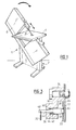
- a band saw 1 comprising a base 2 supporting a saw table 4 and on which is articulated a casing 6 forming a machine frame in the form of a swan neck.
- This casing 6 supports, as we will see later, the drive means of a saw blade 8 in the form of a ribbon and passing through the saw table 4 approximately at its center.
- the housing 6 is pivotally mounted on the base 2 about a horizontal axis 10 located under the saw table 4 near it and away from the passage of the saw blade 8.
- the casing 6 has a flat wall 12 adjacent to the base in which is cut a first lumen 14.
- This lumen 14 is in the form of an arc of a circle whose geometric center is located on an axis 16 around which is articulated a lever 17 on which fixed by one of its ends a threaded rod 18 passing through the lumen 14 to protrude through a second lumen 20 cut from a wall 22 of the base.
- This threaded rod 18 is intended to receive a nut 19 (see Figure 4) for clamping blocking the casing wall 12 relative to the base wall 22.
- This second lumen 20 is rectilinear and slightly inclined at an acute angle with the 'horizontal.
- the base wall 22 extends between two pillars 23 of rectangular section and has an upper edge 24 cut in an arc centered on the axis 10.
- a second locking member 26 secured to the casing wall 12 is located near the upper edge 24 of the base wall 22 and has a threaded part extending beyond the base wall 22.
- a nut 28 is screwed onto this threaded part, which will also make it possible to block the housing wall 12 by tightening with respect to the base wall 22.
- This second locking member 26 is thus located between the pivot axis 10 of the casing and the second lumen 20.
- a standard type balancing cylinder 29 is provided which has one end secured to the base wall 22, and the other end of which is secured to the casing wall 12.
- An indexing element 30 fixed to the casing wall 12 cooperates with holes 32 drilled in the base wall 22. These holes 32 are arranged near the upper edge 24 of the base wall 22 and their axes are located on a circle also centered on the pivot axis 10 of the casing 6.
- This indexing element 30 is shown in section in Figure 3. Referring to it, we see that it has an upper part 34 fixed by any known means on the housing wall 12. This part 34 is located above and near the upper edge 24 and extends from the casing wall 12 to beyond the base wall 22.
- the lower part 36 of the indexing element 30 has a planar face 38 located opposite the upper end 24 and holes 32 in the base wall 22.
- first bore 40 whose bottom is pierced with a bore 42 of smaller diameter to form a shoulder 44.
- the axis of these bores is located on a circle also centered on the axis 10 and passing by the axes of the holes 32.
- the bore 40 slidably receives a cylindrical stud extended at one end by a rod 48 passing through the bore 42.
- the other end of the stud has a frustoconical shape intended to facilitate its introduction into a hole 32.
- a spring 50 resting on the shoulder 44 pushes the stud 46 against the base wall 22 and when the axis of the bore 38 and the hole 32 are aligned, the stud 46 enters the hole 32 thus immobilizing the wall casing in a determined position corresponding to precise angular positions, for example 15 °, 20 ° or others.
- the rod 48 has at its free end a device 52 known per se intended to ensure good grip for removing the stud 46 from the hole 32 and moving it away from the base wall 22 against the stress of the spring 50.
- the base wall 22 has a face 54 facing the casing wall 12.
- the face 54 of the base wall 22 is located in a passing vertical plane by the walls 58 of the pillars 23 facing the casing wall 12.
- the face 56 of the base wall 22 opposite the face 54 is provided with stiffness reinforcements 60 and 62.
- FIG. 5 which shows the housing wall 12, it can be seen that the latter supports a motor 64 projecting from this housing wall 12 towards the base wall 22.
- the motor drives using a belt 66 a drive pulley 68 integral with a guide pulley or flywheel 70, this assembly being located at the lower part of the casing 6 in a swan neck.
- the upper part of the casing 6 comprises a flywheel 72 and the saw blade 8 is stretched over these two flywheels using a tension device not shown.
- a gripping button 74 is provided on the upper part of the casing wall 12 in order to be able to apply the force necessary for the rotation of the casing 6 around the axis 10.
- the casing wall opposite to the wall 12 constitutes a door 76 pivotally mounted on an edge on the discontinuous side of the casing in the form of a swan neck and comprises a button 78 for opening and closing.
- This door 76 also supports the control panel 80 of the band saw 1.
- the nut 19 of the first locking member 18 and the nut 28 of the second locking member are unscrewed 26.
- the element 52 is then pulled from the rod 48 to retract the stud 46 against the spring 50.
- the housing 6 is then pivoted, using the button 74, around the axis 10 to bring it to the desired position.
- the element 52 is then released so that if the angular position of the casing corresponds to a predetermined position by one of the holes 32, the stud 46 is positioned in the corresponding hole 32.
- the stud 46 comes in abutment against the face 56 of the base wall 22. It then suffices to tighten the nuts of the locking members 26 and 18 to lock the housing 6 in position relative to the base 2.
- the band saw is then capable of sawing according to the desired angle of inclination in relation to the saw table.
- a device comprising only two flywheels housed in a compact casing.
- the reliability of the blocking is increased by the presence of two blocking members.
- the points of connection and transmission of forces between the base and the casing are the pivot axis of the casing and the two locking members. These three points are located approximately in the center of the base of the base vertical to the saw table and not cantilevered as in the prior art, which increases the stability of the band saw.
Landscapes
- Engineering & Computer Science (AREA)
- Mechanical Engineering (AREA)
- Sawing (AREA)
- Supporting Of Heads In Record-Carrier Devices (AREA)
- Control And Other Processes For Unpacking Of Materials (AREA)
- Cleaning Implements For Floors, Carpets, Furniture, Walls, And The Like (AREA)
- Harvester Elements (AREA)
- Packaging Of Annular Or Rod-Shaped Articles, Wearing Apparel, Cassettes, Or The Like (AREA)
Priority Applications (1)
| Application Number | Priority Date | Filing Date | Title |
|---|---|---|---|
| AT88402330T ATE64704T1 (de) | 1987-09-16 | 1988-09-15 | Bandsaege mit neigbarem blatt. |
Applications Claiming Priority (2)
| Application Number | Priority Date | Filing Date | Title |
|---|---|---|---|
| FR8712839A FR2620361B1 (fr) | 1987-09-16 | 1987-09-16 | Scie a ruban a lame inclinable |
| FR8712839 | 1987-09-16 |
Publications (2)
| Publication Number | Publication Date |
|---|---|
| EP0309321A1 true EP0309321A1 (de) | 1989-03-29 |
| EP0309321B1 EP0309321B1 (de) | 1991-06-26 |
Family
ID=9354952
Family Applications (1)
| Application Number | Title | Priority Date | Filing Date |
|---|---|---|---|
| EP88402330A Expired - Lifetime EP0309321B1 (de) | 1987-09-16 | 1988-09-15 | Bandsäge mit neigbarem Blatt |
Country Status (6)
| Country | Link |
|---|---|
| US (1) | US4903561A (de) |
| EP (1) | EP0309321B1 (de) |
| AT (1) | ATE64704T1 (de) |
| CA (1) | CA1302845C (de) |
| DE (1) | DE3863413D1 (de) |
| FR (1) | FR2620361B1 (de) |
Cited By (1)
| Publication number | Priority date | Publication date | Assignee | Title |
|---|---|---|---|---|
| CN101406970B (zh) * | 2007-10-12 | 2011-08-24 | 力山工业股份有限公司 | 线锯机及其减震装置 |
Families Citing this family (4)
| Publication number | Priority date | Publication date | Assignee | Title |
|---|---|---|---|---|
| TW563602U (en) * | 2002-05-10 | 2003-11-21 | Pei-Lie Jiang | Orientation adjustment apparatus for band saw machine |
| WO2007111579A1 (en) * | 2006-03-24 | 2007-10-04 | Jourdan James K | Canted and vertical blade assembly |
| US20070221032A1 (en) * | 2006-03-24 | 2007-09-27 | Richen Enterprise, Inc. | Secure band saw work support table |
| US20090044676A1 (en) * | 2007-08-15 | 2009-02-19 | Jourdan James K | Power tilt assembly for band saw |
Citations (2)
| Publication number | Priority date | Publication date | Assignee | Title |
|---|---|---|---|---|
| FR2442704A1 (fr) * | 1978-11-30 | 1980-06-27 | Villeger Jean Pierre | Perfectionnements aux scies a ruban |
| US4503743A (en) * | 1983-04-04 | 1985-03-12 | Chester Ryba | Band saw with tilt and slide frame and quick release vise |
Family Cites Families (4)
| Publication number | Priority date | Publication date | Assignee | Title |
|---|---|---|---|---|
| US442420A (en) * | 1890-12-09 | Band-saw machine | ||
| US797321A (en) * | 1904-10-01 | 1905-08-15 | Benton Rishebarger | Band-saw machine. |
| DE573218C (de) * | 1931-01-08 | 1933-03-30 | Masch Werke Zu Frankfurt A M K | Bandmesserschneid- und -spaltmaschine |
| GB1390455A (en) * | 1971-03-19 | 1975-04-16 | Amada Co Ltd | Vertical band sawing machine |
-
1987
- 1987-09-16 FR FR8712839A patent/FR2620361B1/fr not_active Expired - Lifetime
-
1988
- 1988-09-15 CA CA000577460A patent/CA1302845C/en not_active Expired - Lifetime
- 1988-09-15 EP EP88402330A patent/EP0309321B1/de not_active Expired - Lifetime
- 1988-09-15 AT AT88402330T patent/ATE64704T1/de not_active IP Right Cessation
- 1988-09-15 DE DE8888402330T patent/DE3863413D1/de not_active Expired - Lifetime
- 1988-09-16 US US07/245,677 patent/US4903561A/en not_active Expired - Fee Related
Patent Citations (2)
| Publication number | Priority date | Publication date | Assignee | Title |
|---|---|---|---|---|
| FR2442704A1 (fr) * | 1978-11-30 | 1980-06-27 | Villeger Jean Pierre | Perfectionnements aux scies a ruban |
| US4503743A (en) * | 1983-04-04 | 1985-03-12 | Chester Ryba | Band saw with tilt and slide frame and quick release vise |
Cited By (1)
| Publication number | Priority date | Publication date | Assignee | Title |
|---|---|---|---|---|
| CN101406970B (zh) * | 2007-10-12 | 2011-08-24 | 力山工业股份有限公司 | 线锯机及其减震装置 |
Also Published As
| Publication number | Publication date |
|---|---|
| US4903561A (en) | 1990-02-27 |
| FR2620361A1 (fr) | 1989-03-17 |
| ATE64704T1 (de) | 1991-07-15 |
| DE3863413D1 (de) | 1991-08-01 |
| FR2620361B1 (fr) | 1990-01-19 |
| CA1302845C (en) | 1992-06-09 |
| EP0309321B1 (de) | 1991-06-26 |
Similar Documents
| Publication | Publication Date | Title |
|---|---|---|
| EP0416079B1 (de) | Selbstblockierende abseilvorrichtung mit zwei blockierstellungen | |
| FR2481187A1 (fr) | Appareil pour effectuer une coupe d'onglet avec une scie circulaire portative | |
| CA2233350A1 (fr) | Appareil antichute sur cable vertical | |
| EP0387460A1 (de) | Vorrichtung zum Auf- und Abmontieren von Ventilen und zum Schleifen von Ventilsitzen | |
| FR2754481A1 (fr) | Monture de scie a metaux du type archet monobloc avec dispositif de mise en tension de lame | |
| EP0309321B1 (de) | Bandsäge mit neigbarem Blatt | |
| FR2467670A1 (fr) | Scie munie d'un dispositif d'aspiration de copeaux | |
| FR2642348A1 (fr) | Dispositif pour degager un troncon coupe a longueur sur une scie a moteur | |
| FR2507282A1 (fr) | Dispositif d'articulation autour de deux directions et dispositif de visualisation comportant un tel dispositif d'articulation | |
| FR2645066A1 (fr) | Protecteur de porte-outil degauchisseur | |
| FR2594372A1 (fr) | Support de tronconnage pour meuleuse electrique portative | |
| EP0085636A1 (de) | Schutzvorrichtung für Hobelmaschinen | |
| FR2748959A1 (fr) | Scie a onglet | |
| FR2589098A1 (fr) | Machine pour le sciage semi-automatique de pieces de bois en vue de la realisation de buches de chauffage | |
| CA1150597A (fr) | Dispositif d'abattage d'arbres | |
| FR2763013A1 (fr) | Mecanisme de tension de chaine et de securite pour tronconneuse | |
| FR2613649A1 (fr) | Scie a onglet a table de pivotement donnant une plage de coupe importante | |
| FR2483185A1 (fr) | Scie a os | |
| CH632946A5 (en) | Device for locking a component on a cutting machine | |
| EP0496683A1 (de) | Entaster | |
| EP1249321A1 (de) | Werkzeugmaschine mit Hobel- und Fräsvorrichtungen | |
| FR2771938A1 (fr) | Appareil simulateur d'entrainement equipe d'un dispositif de reglage en position | |
| FR2600829A1 (fr) | Pince de contact electrique a serrage automatique notamment pour la mise a la terre des conducteurs electriques aeriens | |
| FR2553703A1 (fr) | Dispositif de protection pour degauchisseuse | |
| FR2748958A1 (fr) | Scie a onglet avec dispositif d'aspiration |
Legal Events
| Date | Code | Title | Description |
|---|---|---|---|
| PUAI | Public reference made under article 153(3) epc to a published international application that has entered the european phase |
Free format text: ORIGINAL CODE: 0009012 |
|
| AK | Designated contracting states |
Kind code of ref document: A1 Designated state(s): AT BE DE ES GB IT NL SE |
|
| 17P | Request for examination filed |
Effective date: 19890909 |
|
| 17Q | First examination report despatched |
Effective date: 19901019 |
|
| GRAA | (expected) grant |
Free format text: ORIGINAL CODE: 0009210 |
|
| AK | Designated contracting states |
Kind code of ref document: B1 Designated state(s): AT BE DE ES GB IT NL SE |
|
| PG25 | Lapsed in a contracting state [announced via postgrant information from national office to epo] |
Ref country code: SE Effective date: 19910626 Ref country code: NL Effective date: 19910626 Ref country code: GB Effective date: 19910626 Ref country code: ES Free format text: THE PATENT HAS BEEN ANNULLED BY A DECISION OF A NATIONAL AUTHORITY Effective date: 19910626 Ref country code: AT Effective date: 19910626 Ref country code: IT Free format text: LAPSE BECAUSE OF FAILURE TO SUBMIT A TRANSLATION OF THE DESCRIPTION OR TO PAY THE FEE WITHIN THE PRE;WARNING: LAPSES OF ITALIAN PATENTS WITH EFFECTIVE DATE BEFORE 2007 MAY HAVE OCCURRED AT ANY TIME BEFORE 2007. THE CORRECT EFFECTIVE DATE MAY BE DIFFERENT FROM THE ONE RECORDED.SCRIBED TIME-LIMIT Effective date: 19910626 |
|
| REF | Corresponds to: |
Ref document number: 64704 Country of ref document: AT Date of ref document: 19910715 Kind code of ref document: T |
|
| REF | Corresponds to: |
Ref document number: 3863413 Country of ref document: DE Date of ref document: 19910801 |
|
| NLV1 | Nl: lapsed or annulled due to failure to fulfill the requirements of art. 29p and 29m of the patents act | ||
| GBV | Gb: ep patent (uk) treated as always having been void in accordance with gb section 77(7)/1977 [no translation filed] | ||
| PLBE | No opposition filed within time limit |
Free format text: ORIGINAL CODE: 0009261 |
|
| STAA | Information on the status of an ep patent application or granted ep patent |
Free format text: STATUS: NO OPPOSITION FILED WITHIN TIME LIMIT |
|
| 26N | No opposition filed | ||
| PGFP | Annual fee paid to national office [announced via postgrant information from national office to epo] |
Ref country code: DE Payment date: 20070910 Year of fee payment: 20 |
|
| PGFP | Annual fee paid to national office [announced via postgrant information from national office to epo] |
Ref country code: BE Payment date: 20070924 Year of fee payment: 20 |
|
| BE20 | Be: patent expired |
Owner name: S.A. *LUREM Effective date: 20080915 |