EP0309328A1 - Vorrichtung zur Herstellung von Betonbalken - Google Patents
Vorrichtung zur Herstellung von Betonbalken Download PDFInfo
- Publication number
- EP0309328A1 EP0309328A1 EP88402356A EP88402356A EP0309328A1 EP 0309328 A1 EP0309328 A1 EP 0309328A1 EP 88402356 A EP88402356 A EP 88402356A EP 88402356 A EP88402356 A EP 88402356A EP 0309328 A1 EP0309328 A1 EP 0309328A1
- Authority
- EP
- European Patent Office
- Prior art keywords
- mold
- concrete
- construction
- accordance
- casting
- Prior art date
- Legal status (The legal status is an assumption and is not a legal conclusion. Google has not performed a legal analysis and makes no representation as to the accuracy of the status listed.)
- Granted
Links
Images






Classifications
-
- B—PERFORMING OPERATIONS; TRANSPORTING
- B28—WORKING CEMENT, CLAY, OR STONE
- B28B—SHAPING CLAY OR OTHER CERAMIC COMPOSITIONS; SHAPING SLAG; SHAPING MIXTURES CONTAINING CEMENTITIOUS MATERIAL, e.g. PLASTER
- B28B19/00—Machines or methods for applying the material to surfaces to form a permanent layer thereon
-
- B—PERFORMING OPERATIONS; TRANSPORTING
- B28—WORKING CEMENT, CLAY, OR STONE
- B28B—SHAPING CLAY OR OTHER CERAMIC COMPOSITIONS; SHAPING SLAG; SHAPING MIXTURES CONTAINING CEMENTITIOUS MATERIAL, e.g. PLASTER
- B28B1/00—Producing shaped prefabricated articles from the material
- B28B1/08—Producing shaped prefabricated articles from the material by vibrating or jolting
- B28B1/084—Producing shaped prefabricated articles from the material by vibrating or jolting the vibrating moulds or cores being moved horizontally for making strands of moulded articles
-
- B—PERFORMING OPERATIONS; TRANSPORTING
- B28—WORKING CEMENT, CLAY, OR STONE
- B28B—SHAPING CLAY OR OTHER CERAMIC COMPOSITIONS; SHAPING SLAG; SHAPING MIXTURES CONTAINING CEMENTITIOUS MATERIAL, e.g. PLASTER
- B28B23/00—Arrangements specially adapted for the production of shaped articles with elements wholly or partly embedded in the moulding material; Production of reinforced objects
- B28B23/0018—Producing metal-clad stones, such as oven stones
-
- B—PERFORMING OPERATIONS; TRANSPORTING
- B28—WORKING CEMENT, CLAY, OR STONE
- B28B—SHAPING CLAY OR OTHER CERAMIC COMPOSITIONS; SHAPING SLAG; SHAPING MIXTURES CONTAINING CEMENTITIOUS MATERIAL, e.g. PLASTER
- B28B23/00—Arrangements specially adapted for the production of shaped articles with elements wholly or partly embedded in the moulding material; Production of reinforced objects
- B28B23/02—Arrangements specially adapted for the production of shaped articles with elements wholly or partly embedded in the moulding material; Production of reinforced objects wherein the elements are reinforcing members
- B28B23/04—Arrangements specially adapted for the production of shaped articles with elements wholly or partly embedded in the moulding material; Production of reinforced objects wherein the elements are reinforcing members the elements being stressed
- B28B23/046—Post treatment to obtain pre-stressed articles
-
- B—PERFORMING OPERATIONS; TRANSPORTING
- B28—WORKING CEMENT, CLAY, OR STONE
- B28B—SHAPING CLAY OR OTHER CERAMIC COMPOSITIONS; SHAPING SLAG; SHAPING MIXTURES CONTAINING CEMENTITIOUS MATERIAL, e.g. PLASTER
- B28B23/00—Arrangements specially adapted for the production of shaped articles with elements wholly or partly embedded in the moulding material; Production of reinforced objects
- B28B23/02—Arrangements specially adapted for the production of shaped articles with elements wholly or partly embedded in the moulding material; Production of reinforced objects wherein the elements are reinforcing members
- B28B23/22—Arrangements specially adapted for the production of shaped articles with elements wholly or partly embedded in the moulding material; Production of reinforced objects wherein the elements are reinforcing members assembled from preformed parts
-
- B—PERFORMING OPERATIONS; TRANSPORTING
- B28—WORKING CEMENT, CLAY, OR STONE
- B28B—SHAPING CLAY OR OTHER CERAMIC COMPOSITIONS; SHAPING SLAG; SHAPING MIXTURES CONTAINING CEMENTITIOUS MATERIAL, e.g. PLASTER
- B28B3/00—Producing shaped articles from the material by using presses; Presses specially adapted therefor
- B28B3/20—Producing shaped articles from the material by using presses; Presses specially adapted therefor wherein the material is extruded
-
- B—PERFORMING OPERATIONS; TRANSPORTING
- B28—WORKING CEMENT, CLAY, OR STONE
- B28B—SHAPING CLAY OR OTHER CERAMIC COMPOSITIONS; SHAPING SLAG; SHAPING MIXTURES CONTAINING CEMENTITIOUS MATERIAL, e.g. PLASTER
- B28B3/00—Producing shaped articles from the material by using presses; Presses specially adapted therefor
- B28B3/20—Producing shaped articles from the material by using presses; Presses specially adapted therefor wherein the material is extruded
- B28B3/22—Producing shaped articles from the material by using presses; Presses specially adapted therefor wherein the material is extruded by screw or worm
- B28B3/228—Slipform casting extruder, e.g. self-propelled extruder
Definitions
- the present invention relates to a method in accordance with the preamble of claim 1 for fabrication of concrete beams.
- the invention also concerns a slipforming extruder for the implementation of the method as well as a beam construction applicable for fabrication by the slipforming extruder.
- the industrial production of pillars and beams aims to concentrate on products characterized by maximally long production series, maximally low material costs and a rationalized production technology without at the same time compromising a sufficiently broad selection of products.
- the most frequently applied method of conventional technology applied in the production of pillars and beams has been mold casting in which the pillars and beams are cast into individually fabricated wooden or steel molds.
- the molds are almost invariably placed horizontally and casting is made, using a relatively fluid mix of concrete, by feeding the fluid mix from a hopper under manual control into the mold, whereupon the cast mix is vibrated by high-frequency vibrators that may be either manually operated or permanently mounted to the molds.
- frogs and brackets Prior to casting, frogs and brackets are prepared into the molds. Further, any specific additional reinforcement required by the element design is preplaced into the molds.
- Disadvantages of prior art technology include, i.a., the necessity of using fluid mix due to the undeveloped compaction techniques. This results in both an increased hardening time and, moreover, a higher consumption of cement in order to achieve a high final strength.
- the reinforcement operation involves a high proportion of manual skills as well as the fabrication of molds. Bracket constructions required to form element frogs require a high amount of manual work on the molds in addition to the extra reinforcements required.
- a disadvantage of reinforced concrete beams is that their beam height exceeds that of the slabs carried by the beam, which results in an imperfection of leaving the lower flange of the beam visible underneath the slabs thus making it impossible to obtain a smooth lower surface for a combination beam/slab floor construction.
- a possible approach has been sought from the prestressing technology of beams, but at the minimum required height of beams, however, the excessive negative deflection that results from the prestress has presented problems.
- steel beam constructions are capable of offering a sufficiently low height of beams leaving only the flanges supporting the slabs visible below the slab floor.
- a complication involved with the use of steel beams is the need for fire protection, which by itself forms a discontinuity at the underside of the slab floor.
- sagging beams are a source of aesthetic discomfort.
- the aim of the present invention is to overcome the disadvantages associated with the aforedescribed prior art technology and obtain an entirely new kind of method for production of concrete beams.
- the invention is based on fabricating beams with help of a stationary slipforming extruder into a desired mold in a continuous horizontal slip-form casting process by incorporating the casting mold into an integral part of the cast beam structure which thus is formed into a composite structure.
- An advantageous casting method is implemented using extremely stiff concrete mix compacted by a shear compaction method, thereby disposing of the need of conventional high-frequency vibrators.
- the invention provides outstanding benefits.
- Implementation of the invention makes it possible to produce individually designed products on a production line equipped with automated manufacturing technology.
- each mold may be individually designed as to its shape, surface details, and dimensions.
- the final products may be fabricated by cutting the hardened product, e.g., with a saw, to desired length. Due to the efficiency of the shear compaction method and use of extremely stiff concrete, pillars and beams fabricated according to the method are of remarkably higher strength compared with those manufactured using conventional methods. Instead of the conventionally applied strength grades of 20...50 MN/m2, grades up to 50...150 MN/m2 are achieved. Correspondingly, products manufactured with help of the method are essentially thinner than those of conventional technology.
- Prestressing tendons are placed in a hollow-cored section of the concrete construction and their tensioning force is backed by an already hardened concrete. Consequently, stress losses in the tendons remain minimal.
- products manufactured are of extremely high strength and accept, when required, relatively high stress forces and quantities of tensioning tendons.
- Figure 1 illustrates a typical beam extruder for fabrication of a continuous beam structure in a horizontal slip-form casting process.
- the apparatus comprises a stationary casting station 1 resting on a floor 2 of an industrial hall.
- mold parts 3 and 4 are movable upon the hall floor 2 during the casting process.
- the actual casting process is started when a concrete mix feeding hopper 5 of the extruder 1 is filled with stiff mix 6.
- the first auger 7 of the extruder 1 is started into rotation, driven by a rotational drive motor 8, and commences feeding the mix towards a rear part 9 of the extruder, where the actual formation and compaction of the continuous beam takes place.
- the final compaction of mix takes place in the rear part 9 of the extruder 1 with help of a second feeding/compacting auger (not shown).
- the second auger is rotated by the same drive motor 8 as the first auger 7.
- the second auger flight is rotated and subjected to a longitudinal reciprocating movement by means of an eccentric drive motor 10.
- the extruder auger forces the stiff mix into a closed mold space 3, 4 while simultaneously performing a longitudinal movement of compacting action, the stiff mix is compacted in a continuous slip-form casting process into a desired shape.
- the auger is followed by a tubular extension mandrel (not shown) that promotes further compaction and creates a duct in a desired location of the continuous beam structure.
- the duct may later be utilized for insertion of reinforcement steel tendons.
- the movement and shape of the mandrel may be adapted to achieve a desired shape of the duct, which provides at a later state an improved adhesion of injected concrete to the concrete of the beam.
- the actual lower part of the mold for the beam in the continuous slip-form casting is provided by a module-dimensioned steel plate 3, profiled in the desired shape of the beam structure's bottom surface.
- the other part of the mold forming the upper part is provided by a steel plate 4 profiled in an equal manner.
- the steel parts 3 and 4 of the mold are clamped together either before the extruder station 1 or underneath it so that the clamping is performed by means of quick-mounting clamps (not shown) before reaching the actual casting point.
- the steel upper part 4 of the mold which is profiled to the shape of the beam's upper surface, is assembled above the extruder 1 before reaching an actual compaction point 9.
- the lower part 3 of the mold and the upper part 4 of the mold are later clamped together by quick-mounting clamps to be described later so as to form a tight, continuous tubular space about the second auger of the extruder.
- Concrete mix is slip-form cast into the tubular mold space by extrusion with help of the auger in a continuous slip-form casting process so that the mix is compacted into a shape determined by the lower and upper mold structures whereby the cast structure glides forward in the form of a continuous, integral, cast combination mold/beam construction supported by separate bearing blocks 11 mounted on a casting bed 2.
- the moving of the beam on the casting bed 2 is actuated by the back pressure exerted by the second auger of the extruder.
- the glide movement actuating force may be increased by supplying an auxiliary force of, e.g, constant speed or constant force into the steady movement of the continuous beam by means of, e.g., pulling actuators placed between the mold bed and the beam structure.
- a protective shield in the form of a blanket (not shown) can be extended over the integral cast beam structure in order to protect the casting bed from heat losses during heat treatment.
- the dismantling of individual elements is started by first folding the protective blanket away from above the mold structures to allow dismantling of the mold structures 3 and 4. Dismantling is done by removing the quick-mounting clamps and then stripping the upper part 4 of the mold, which is transferred to the vicinity of the extruder 1 for reuse. Correspondingly, the lower part 3 of the mold is stripped in a recess 12 located in the casting bed 2. If the upper or lower part of the mold is to remain an integral part of the final structure of the beam, then this mold part will not be dismantled at this stage from the concrete section of the beam structure.
- elements 14 After hardening of concrete, the elements are cut into individual products to customer specifications by means of a cutting saw 13. Following the cutting operation, elements 14 can be transferred by means of a separate clamping hoist 15 to an intermediate storage.
- FIG. 2 illustrates in detail the construction of the extruder 1.
- a second auger 16 together with its tubular extension mandrel is arranged to form an extension of a first auger 7 on the same drive shaft.
- a possible adaptation of the augers is to provide independent operation of the augers by powering them with separate drive motors.
- An eccentric drive motor 10 is connected by a lever 18 to the drive shaft of the augers 7 and 16 in order to achieve a reciprocating motion of the augers.
- Figure 3 illustrates a mold construction 3 and 4 of circular cross-section.
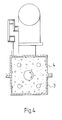
- Figure 4 illustrates a mold construction 3 and 4 of square cross-section.
- Figure 5 illustrates in detail the mold construction 3 and 4 of circular cross-section.
- the upper mold part 4 of a semicircular cross-section includes flanges 19 extending in the direction of the mold's longitudinal axis and protruding radially outward at the ends of the semicircle.
- the upper mold part 4 has a seal lip 22 extending marginally over the flanges 19.
- the lower mold part includes axially aligned, radially protruding flanges 20 and a groove 21, close to the corners of flanges 20, designed to mate with the seal lip 21.
- the mold parts are clamped on both sides with help of clamps 23, which can be, e.g., spring clamps.
- Figure 6 illustrates another preferred mold construction.
- the lower mold part 3 is a planar plate, which rests on chains 24 of a chain conveyor while the chains 24 are gliding in chain troughs on the upper surface of the bed 2.
- the lower mold part carries the U-shaped upper mold part 4 incorporating clamping flanges 26.
- Figure 7 illustrates a U-shaped lower mold part 3, analogous to that of the embodiment illustrated in Fig. 6.
- Figure 8 illustrates a cross-section of a beam fabricated using the mold construction shown in Fig. 6.
- the concrete section 32 shaped by the upper mold part 4 is provided with a duct 31 to accept pretensioning steel tendons 31.
- the clamping flanges 26 are formed to become a part of the reinforcing structure.
- the width a of the flanges is approx. 100 mm.
- the variation range of dimension B can be 300...600 mm.
- Typical dimensions for beam height H are 230...360 mm and for thickness t of the mold shell 4, in the range 6.5...8 mm.
- a correspondingly shaped lower mold part 3 can alternatively be used as the mold part to remain integral with the beam structure.
- the beam cross section can be designed to extend below the underside of a slab 33. This approach is particularly applicable to long spans.
- the slab 33 is jointed to the beam by means of a cast concrete joint 35.
- Figure 10a illustrates a beam construction where the upper mold part 4 is designed to remain an integral part of the final beam structure and, consequently, to perform as a composite construction with the actual concrete structure 32 of the beam.
- the lower mold part 3 has been stripped in the production phases.
- a major section of the beam's mold structure forms an essential part of the beam's final construction and performs as a steel reinforcement.
- the compression load carrying area of the beam is formed by the profiled steel shell of the upper surface and by concrete located in the upper part of the beam. Load carrying capacity of the compressively loaded beam area may be increased by using a mold part 4 of greater strength in the beam's upper section or, alternatively, by complementing the steel reinforcement of the upper section with an additional steel reinforcement 27.
- Fig 10b Illustrated in Fig 10b is the form of the additional steel reinforcement.
- that part of the beam's reinforcement which is designed to carry tensile stress is provided by the lower flanges 26 of the mold part 4 as well as by prestressing tendons 29, which are first inserted into a longitudinal duct 30 of the beam after the casting operation to add additional reinforcement to the beam, then post-tensioned, and finally injected to meet the intended load carrying conditions.
- Selection of design parameters on the tensile-stress-carrying side of the beam is made by varying the number of tendon strands and the strength of the mold flange section.
- the dimensioning of the beam construction for fire resistance does not require a separate fire protection of the lower surface because a cast concrete 35 jointing the slabs 33 and the beam construction forms a dowel with a sufficient load carrying capacity to support the slabs on the beam.
- the separation of the slab elements from the beam construction is prevented by means of additional steel reinforcements 27 anchored to the seams between the elements.
- the fire proctection of the beam's upper surface in a fire situation is provided by the grouting of gaps between the beams and the slab floor.
- the stranded tendons in the lower part of the beam that provide reinforcement against tensile stress are secured by a protective concrete layer, sufficiently thick at the underside.
- support for the slab with respect to the beam construction is provided by dowels 40 placed in the fire-exposed part of the beam construction, whereby the grouting concrete in the gap between the beam construction and the slabs carries, by virtue of the dowel 40, the weight of slab floor weight without the participation of flange parts 26 of the beam, and consequently, the flange parts 26 of the beam perform only as temporary supports for the slabs and as a backing surface for the compressive reaction force of the prestressed tendon strands.
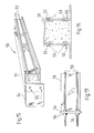
- Figures 12 and 13 illustrate the construction of a beam-to-pillar joint.
- Beams 36 are jointed to each other across a pillar 37 by bolting the beams to plates 38 embracing the pillar 37, with help of tensioned frictional bolts 39 extending through the beam.
- Figs. 14a...14e An alternative method for jointing the beams to the pillar is illustrated in Figs. 14a...14e.
- the beam 36 is cut to a predetermined length in accordance with Fig. 14a so that the shell part 4 of the beam is flush with the beam end.
- a jointing plate 41 whose outer dimensions exceed those of the beam cross-section is welded to the end of the beam 36.
- the center of the jointing plate 41 is provided with a opening 42 for the pillar console and with holes 43 at the corners for securing bolts.
- the beam end is worked to have a recess compatible with the opening 42.
- the jointing plate 41 is also provided with a tube 48 which is inserted into a cavity 30 of the beam 36 in the installation phase.
- An advantageous length of the tube 48 is about 200...500 mm.
- the joint of the cavity 30 and the tube 48 may be bonded by, e.g., grouting or epoxy resin.
- Illustrated in Fig. 14d is a side view of the jointing of the beams 36 to the pillar construction illustrated in Fig. 14c.
- the beams 36 are supported on a pillar console 44 of the pillar 37 by the opening hole 42 of the jointing plate 41, and the beams are jointed to each other across the pillar 37 by bolting the beams to the jointing plates 41 at both sides of the pillar with bolts 45.
- Mounting tolerances may be taken into account in the construction by using spacers 46 inserted between the beams 36 and the pillar structures 37.
- Figure 14e illustrates the pillar-beam joint viewed from the direction of the beam 36.
- the spacers 47 are installed between the pillar console 44 and the jointing plate 41.
- Mold parts 51 illustrated in Figs. 15, 16, and 17 together with their end plates 54 may be prefabricated by, e.g,. a subcontracting machine shop, allowing the concrete product manufacturer to start production operations directly with the filling of the mold 51 with a concrete mix of desired strength grade. Casting is most advantageously done using a conventional manual method to avoid costly investments in additional machinery.
- the mold 51 is oriented for the casting operation in an inverted position compared to that shown in the diagrams.
- the sides of the mold 51 may be provided with longitudinal grooves 52 aligned with the length of a beam 50. After hardening of the concrete, the auxiliary steel tendons 53 are inserted in holes 55 of end plates 54.
- the grooves 52 together with the auxiliary steel tendons 53 act as dowels for the surrounding concrete. Further, the need for postinjections is found superfluous since the auxiliary steel tendons 53 are immersed in the grouting concrete of the seam between the beam and the slabs, thus disposing of additional corrosion and fire protection.
- the auxiliary steel tendons 53 of the lower section of the beam 50 are prestressed either with help of nuts 56 or by using a separate prestressing apparatus.
- the steel tendons 53 of the beam's upper section perform as a compressive stress reinforcement which adds to the compressive stress load capacity of the steel mold structure 51 and the concrete. References made to the upper and lower sections of the beam 50 are applicable to the corresponding beam sections at the installation stage. As described in the aforegoing examples, the reinforcement steel tendons 53 of the upper and lower section may be advantageously utilized in jointing to a pillar.
- Figure 18 illustrates an alternative embodiment of the mold.
- the auxiliary steel reinforcement is implemented by inserting conventional ribbed steel wires 58 into the upper surface of cast concrete in a mold 57.
- FIG 19 illustrates an alternative arrangement for fabrication of beam elements in accordance with the invention.
- Steel plate profiles 59 manufactured by, e.g., rolling from thin plate material, are placed on supports 61 on an elongated casting bed 60 so that the profiles 59 are displaced positively free from the casting bed 60.
- the thin-plate profiles 59 may be selected to be of a constant or modular length, e.g, as of 10...12 meters.
- the length of the profiles 59 may go up to 20 meters, with the only limitation being principally dictated by the desired transportation and handling length.
- the steel profiles 59 may be joined together on the casting bed by welding into a continuous length profile that extends from one end of a long casting bed to the other end reaching lengths up to 50...150 meters.
- pretensioning tendons 67 are inserted in the steel profiles 59 and tensioned with a pretensioning apparatus 62 against prestressing anchor posts 63.
- Intended sawing points 64 of the beams may be complemented with a separate clasping reinforcement 65, which accepts cleaving stresses induced at the beam end by the prestressing tendons.
- the clasping reinforcements 65 may be inserted by 1...3 pieces in the vicinity of each cutting point.
- the mold construction 59 may be filled using any conventional casting method by feeding the concrete mix into the mold, vibrating the mix, and finally trowelling the upper surface of the cast concrete. After these operations, the cast concrete is covered by a protective blanket and heat cured until a sufficient release strength is achieved.
- the elements are cut to desired lengths while elevated on the supports 61, using a separate cutting saw 66 which is capable of sawing both the steel mold part, the prestressing tendons, and the cured concrete in one operation. Due to the supports 61, damage to the casting bed 60 is avoided during sawing. After cutting, the fabricated elements are ready for delivery to the construction site for installation.
- Figure 20 illustrates a beam element fabricated using the arrangement illustrated in Fig. 19 and having the prestressing tendons 67 surrounded by a clasping reinforcement 65.
Landscapes
- Engineering & Computer Science (AREA)
- Chemical & Material Sciences (AREA)
- Ceramic Engineering (AREA)
- Mechanical Engineering (AREA)
- Manufacturing & Machinery (AREA)
- On-Site Construction Work That Accompanies The Preparation And Application Of Concrete (AREA)
- Rod-Shaped Construction Members (AREA)
Priority Applications (1)
| Application Number | Priority Date | Filing Date | Title |
|---|---|---|---|
| AT88402356T ATE69194T1 (de) | 1987-09-22 | 1988-09-19 | Vorrichtung zur herstellung von betonbalken. |
Applications Claiming Priority (4)
| Application Number | Priority Date | Filing Date | Title |
|---|---|---|---|
| FI874133A FI874133L (fi) | 1987-09-22 | 1987-09-22 | Foerfarande och anordning foer framstaellning av betongstomelement, isynnerhet bjaelkar. |
| FI874133 | 1987-09-22 | ||
| FI875327A FI875327A7 (fi) | 1987-09-22 | 1987-12-02 | Menetelmä ja laite betonirunkoelementtienetenkin palkkien valmistamiseksi. |
| FI875327 | 1987-12-02 |
Publications (2)
| Publication Number | Publication Date |
|---|---|
| EP0309328A1 true EP0309328A1 (de) | 1989-03-29 |
| EP0309328B1 EP0309328B1 (de) | 1991-11-06 |
Family
ID=26158231
Family Applications (1)
| Application Number | Title | Priority Date | Filing Date |
|---|---|---|---|
| EP88402356A Expired - Lifetime EP0309328B1 (de) | 1987-09-22 | 1988-09-19 | Vorrichtung zur Herstellung von Betonbalken |
Country Status (5)
| Country | Link |
|---|---|
| EP (1) | EP0309328B1 (de) |
| DE (1) | DE3866074D1 (de) |
| DK (1) | DK524088A (de) |
| FI (1) | FI875327A7 (de) |
| NO (1) | NO884076L (de) |
Cited By (4)
| Publication number | Priority date | Publication date | Assignee | Title |
|---|---|---|---|---|
| EP0462611A3 (en) * | 1990-06-21 | 1992-07-29 | Immobiliare Centro Nord S.P.A. | Process and apparatus for producing reinforced concrete components |
| EP0771627A1 (de) * | 1995-11-02 | 1997-05-07 | Streek Holding B.V. | Verfahren und Vorrichtung zum Herstellen von einem länglichen Gegenstand aus einem aushärtenden Material |
| WO1998034869A1 (de) * | 1997-02-08 | 1998-08-13 | Frank Thielow | Aufzug, insbesondere zur verbindung verschiedener etagen in gebäuden und verfahren zu dessen herstellung |
| CN106149961A (zh) * | 2015-04-22 | 2016-11-23 | 辽宁易筑建筑材料有限公司 | 一种机械成型干硬性混凝土底板及其制作方法 |
Families Citing this family (1)
| Publication number | Priority date | Publication date | Assignee | Title |
|---|---|---|---|---|
| CN113752357B (zh) * | 2021-09-30 | 2026-05-12 | 河南水建集团有限公司 | 一种用于管片流水线化生产取样的试模托架 |
Citations (6)
| Publication number | Priority date | Publication date | Assignee | Title |
|---|---|---|---|---|
| FR805289A (fr) * | 1935-08-01 | 1936-11-16 | Système de béton, armé par tubes d'acier creux | |
| AT156911B (de) * | 1938-01-14 | 1939-09-11 | Fritz Ing Hoffmann | Verfahren und Einrichtung zur Herstellung von Gußkörpern aus Beton oder Eisenbeton u. dgl., insbesondere von Masten, Pfählen, Säulen, Röhren usw. |
| US2794231A (en) * | 1952-10-15 | 1957-06-04 | Pacific Union Metal Company | Portable equipment for making concrete piles |
| GB984389A (en) * | 1962-01-13 | 1965-02-24 | Skanska Cementgjuteriet Ab | Improvements in or relating to methods of casting concrete products and devices therefor |
| DE2138808A1 (de) * | 1970-08-04 | 1972-02-10 | Vereinigte Metallwerke Ranshofen-Berndorf AG, Braunau (Österreich) | Vorrichtung zum Füllen und Gießen von Trägern, Stützen, Säulen und dgl., Schalen-Kernbauweise |
| US3922124A (en) * | 1971-08-12 | 1975-11-25 | Georg Bjorhaag | Sliding mould for concrete piles including slipform and rollers |
-
1987
- 1987-12-02 FI FI875327A patent/FI875327A7/fi not_active Application Discontinuation
-
1988
- 1988-09-14 NO NO88884076A patent/NO884076L/no unknown
- 1988-09-19 DE DE8888402356T patent/DE3866074D1/de not_active Expired - Fee Related
- 1988-09-19 EP EP88402356A patent/EP0309328B1/de not_active Expired - Lifetime
- 1988-09-21 DK DK524088A patent/DK524088A/da not_active Application Discontinuation
Patent Citations (6)
| Publication number | Priority date | Publication date | Assignee | Title |
|---|---|---|---|---|
| FR805289A (fr) * | 1935-08-01 | 1936-11-16 | Système de béton, armé par tubes d'acier creux | |
| AT156911B (de) * | 1938-01-14 | 1939-09-11 | Fritz Ing Hoffmann | Verfahren und Einrichtung zur Herstellung von Gußkörpern aus Beton oder Eisenbeton u. dgl., insbesondere von Masten, Pfählen, Säulen, Röhren usw. |
| US2794231A (en) * | 1952-10-15 | 1957-06-04 | Pacific Union Metal Company | Portable equipment for making concrete piles |
| GB984389A (en) * | 1962-01-13 | 1965-02-24 | Skanska Cementgjuteriet Ab | Improvements in or relating to methods of casting concrete products and devices therefor |
| DE2138808A1 (de) * | 1970-08-04 | 1972-02-10 | Vereinigte Metallwerke Ranshofen-Berndorf AG, Braunau (Österreich) | Vorrichtung zum Füllen und Gießen von Trägern, Stützen, Säulen und dgl., Schalen-Kernbauweise |
| US3922124A (en) * | 1971-08-12 | 1975-11-25 | Georg Bjorhaag | Sliding mould for concrete piles including slipform and rollers |
Cited By (8)
| Publication number | Priority date | Publication date | Assignee | Title |
|---|---|---|---|---|
| EP0462611A3 (en) * | 1990-06-21 | 1992-07-29 | Immobiliare Centro Nord S.P.A. | Process and apparatus for producing reinforced concrete components |
| US5316461A (en) * | 1990-06-21 | 1994-05-31 | Immobiliare Centro Nord S.P.A. | Apparatus for producing reinforced concrete components |
| EP0771627A1 (de) * | 1995-11-02 | 1997-05-07 | Streek Holding B.V. | Verfahren und Vorrichtung zum Herstellen von einem länglichen Gegenstand aus einem aushärtenden Material |
| NL1001558C2 (nl) * | 1995-11-02 | 1997-05-13 | Streek Holding B V | Werkwijze en inrichting voor het uit hardbaar materiaal vervaardigen van een langwerpig voorwerp. |
| WO1998034869A1 (de) * | 1997-02-08 | 1998-08-13 | Frank Thielow | Aufzug, insbesondere zur verbindung verschiedener etagen in gebäuden und verfahren zu dessen herstellung |
| WO1998034872A1 (de) * | 1997-02-08 | 1998-08-13 | Frank Thielow | Hebebühne, insbesondere für kraftfahrzeuge und verfahren zur herstellung der hebebühne |
| CN106149961A (zh) * | 2015-04-22 | 2016-11-23 | 辽宁易筑建筑材料有限公司 | 一种机械成型干硬性混凝土底板及其制作方法 |
| CN106149961B (zh) * | 2015-04-22 | 2019-03-29 | 辽宁易筑建筑材料有限公司 | 一种机械成型干硬性混凝土底板及其制作方法 |
Also Published As
| Publication number | Publication date |
|---|---|
| DE3866074D1 (de) | 1991-12-12 |
| FI875327L (fi) | 1989-03-23 |
| NO884076L (no) | 1989-03-28 |
| NO884076D0 (no) | 1988-09-14 |
| EP0309328B1 (de) | 1991-11-06 |
| DK524088D0 (da) | 1988-09-21 |
| FI875327A0 (fi) | 1987-12-02 |
| FI875327A7 (fi) | 1989-03-23 |
| DK524088A (da) | 1989-03-23 |
Similar Documents
| Publication | Publication Date | Title |
|---|---|---|
| CA2257739C (en) | Method of strengthening an existing reinforced concrete member | |
| JP2001026909A (ja) | 橋桁に於けるコンクリート版付き立体トラスを用いた床版の結合構造 | |
| EP0309328B1 (de) | Vorrichtung zur Herstellung von Betonbalken | |
| JP3836920B2 (ja) | 橋脚張り出し部の施工方法 | |
| CN108068194B (zh) | 用于浇筑预制混凝土产品的方法和设备 | |
| CN1076776C (zh) | 预制构件构成的建筑物 | |
| JP3208530B2 (ja) | プレキャストコンクリート型枠及びこれを用いた構造体 | |
| JP2912554B2 (ja) | ガードフェンス | |
| AU697180B2 (en) | Method and apparatus for producing concrete elements | |
| JP3275017B2 (ja) | プレキャスト部材を使用したケーソンの製作方法 | |
| JPH06129114A (ja) | 既設柱列構造物の補修工法 | |
| JPH0625406B2 (ja) | カンチレバー工法による橋梁架設方法 | |
| JPS6151524B2 (de) | ||
| NL2031784B1 (en) | A method for providing a concrete pile and a concrete pile | |
| JP2504195B2 (ja) | 躯体の施工方法 | |
| EP0229751B1 (de) | Gleitfertiger für Hohldielen aus Beton | |
| JPH0913486A (ja) | コンクリート構造体 | |
| JP2588117B2 (ja) | コンクリート構造物を築造する方法 | |
| EP0295939A2 (de) | Betonfachwerksystem, Verfahren sowie Vorrichtung zur Herstellung von systemkompatiblen Säulen | |
| JP2709870B2 (ja) | 既設柱列構造物の補修用支持枠体 | |
| CN118418284A (zh) | 一种预制梯段板的单模生产方法及楼梯连接结构 | |
| EP0235114A2 (de) | Gleitfertiger für Hohldielen aus Beton | |
| JP2942370B2 (ja) | 鉄筋コンクリート造の梁、壁などの鉛直方向打継ぎ部の型枠工法およびこの工法に用いるガイド金具 | |
| JPH08333828A (ja) | コンクリート構造物の施工方法 | |
| JPH10237993A (ja) | プレキャストコンクリート型枠及びこれを用いた構造体 |
Legal Events
| Date | Code | Title | Description |
|---|---|---|---|
| PUAI | Public reference made under article 153(3) epc to a published international application that has entered the european phase |
Free format text: ORIGINAL CODE: 0009012 |
|
| AK | Designated contracting states |
Kind code of ref document: A1 Designated state(s): AT BE CH DE ES FR GB GR IT LI NL SE |
|
| 17P | Request for examination filed |
Effective date: 19890719 |
|
| 17Q | First examination report despatched |
Effective date: 19900222 |
|
| RAP1 | Party data changed (applicant data changed or rights of an application transferred) |
Owner name: LOHJA PARMA ENGINEERING LPE OY |
|
| GRAA | (expected) grant |
Free format text: ORIGINAL CODE: 0009210 |
|
| AK | Designated contracting states |
Kind code of ref document: B1 Designated state(s): AT BE CH DE ES FR GB GR IT LI NL SE |
|
| PG25 | Lapsed in a contracting state [announced via postgrant information from national office to epo] |
Ref country code: LI Effective date: 19911106 Ref country code: GR Free format text: LAPSE BECAUSE OF FAILURE TO SUBMIT A TRANSLATION OF THE DESCRIPTION OR TO PAY THE FEE WITHIN THE PRESCRIBED TIME-LIMIT Effective date: 19911106 Ref country code: ES Free format text: THE PATENT HAS BEEN ANNULLED BY A DECISION OF A NATIONAL AUTHORITY Effective date: 19911106 Ref country code: CH Effective date: 19911106 Ref country code: BE Effective date: 19911106 Ref country code: AT Effective date: 19911106 |
|
| REF | Corresponds to: |
Ref document number: 69194 Country of ref document: AT Date of ref document: 19911115 Kind code of ref document: T |
|
| REF | Corresponds to: |
Ref document number: 3866074 Country of ref document: DE Date of ref document: 19911212 |
|
| ITF | It: translation for a ep patent filed | ||
| REG | Reference to a national code |
Ref country code: CH Ref legal event code: PL |
|
| ET | Fr: translation filed | ||
| PGFP | Annual fee paid to national office [announced via postgrant information from national office to epo] |
Ref country code: SE Payment date: 19920813 Year of fee payment: 5 |
|
| PLBE | No opposition filed within time limit |
Free format text: ORIGINAL CODE: 0009261 |
|
| STAA | Information on the status of an ep patent application or granted ep patent |
Free format text: STATUS: NO OPPOSITION FILED WITHIN TIME LIMIT |
|
| PG25 | Lapsed in a contracting state [announced via postgrant information from national office to epo] |
Ref country code: GB Effective date: 19920919 |
|
| PGFP | Annual fee paid to national office [announced via postgrant information from national office to epo] |
Ref country code: FR Payment date: 19920922 Year of fee payment: 5 |
|
| PGFP | Annual fee paid to national office [announced via postgrant information from national office to epo] |
Ref country code: NL Payment date: 19920930 Year of fee payment: 5 |
|
| 26N | No opposition filed | ||
| PGFP | Annual fee paid to national office [announced via postgrant information from national office to epo] |
Ref country code: DE Payment date: 19921106 Year of fee payment: 5 |
|
| GBPC | Gb: european patent ceased through non-payment of renewal fee |
Effective date: 19920919 |
|
| PG25 | Lapsed in a contracting state [announced via postgrant information from national office to epo] |
Ref country code: SE Effective date: 19930920 |
|
| PG25 | Lapsed in a contracting state [announced via postgrant information from national office to epo] |
Ref country code: NL Effective date: 19940401 |
|
| NLV4 | Nl: lapsed or anulled due to non-payment of the annual fee | ||
| PG25 | Lapsed in a contracting state [announced via postgrant information from national office to epo] |
Ref country code: FR Free format text: LAPSE BECAUSE OF NON-PAYMENT OF DUE FEES Effective date: 19940531 |
|
| PG25 | Lapsed in a contracting state [announced via postgrant information from national office to epo] |
Ref country code: DE Effective date: 19940601 |
|
| REG | Reference to a national code |
Ref country code: FR Ref legal event code: ST |
|
| EUG | Se: european patent has lapsed |
Ref document number: 88402356.5 Effective date: 19940410 |
|
| PG25 | Lapsed in a contracting state [announced via postgrant information from national office to epo] |
Ref country code: IT Free format text: LAPSE BECAUSE OF NON-PAYMENT OF DUE FEES;WARNING: LAPSES OF ITALIAN PATENTS WITH EFFECTIVE DATE BEFORE 2007 MAY HAVE OCCURRED AT ANY TIME BEFORE 2007. THE CORRECT EFFECTIVE DATE MAY BE DIFFERENT FROM THE ONE RECORDED. Effective date: 20050919 |