EP0309344B1 - Verbindungsvorrichtung für eine Lenksäule und ein mit dieser Vorrichtung ausgestattetes Fahrzeug - Google Patents
Verbindungsvorrichtung für eine Lenksäule und ein mit dieser Vorrichtung ausgestattetes Fahrzeug Download PDFInfo
- Publication number
- EP0309344B1 EP0309344B1 EP88402379A EP88402379A EP0309344B1 EP 0309344 B1 EP0309344 B1 EP 0309344B1 EP 88402379 A EP88402379 A EP 88402379A EP 88402379 A EP88402379 A EP 88402379A EP 0309344 B1 EP0309344 B1 EP 0309344B1
- Authority
- EP
- European Patent Office
- Prior art keywords
- ring
- yoke
- shaft
- threaded element
- steering column
- Prior art date
- Legal status (The legal status is an assumption and is not a legal conclusion. Google has not performed a legal analysis and makes no representation as to the accuracy of the status listed.)
- Expired - Lifetime
Links
Images


Classifications
-
- B—PERFORMING OPERATIONS; TRANSPORTING
- B62—LAND VEHICLES FOR TRAVELLING OTHERWISE THAN ON RAILS
- B62D—MOTOR VEHICLES; TRAILERS
- B62D1/00—Steering controls, i.e. means for initiating a change of direction of the vehicle
- B62D1/02—Steering controls, i.e. means for initiating a change of direction of the vehicle vehicle-mounted
- B62D1/16—Steering columns
-
- F—MECHANICAL ENGINEERING; LIGHTING; HEATING; WEAPONS; BLASTING
- F16—ENGINEERING ELEMENTS AND UNITS; GENERAL MEASURES FOR PRODUCING AND MAINTAINING EFFECTIVE FUNCTIONING OF MACHINES OR INSTALLATIONS; THERMAL INSULATION IN GENERAL
- F16B—DEVICES FOR FASTENING OR SECURING CONSTRUCTIONAL ELEMENTS OR MACHINE PARTS TOGETHER, e.g. NAILS, BOLTS, CIRCLIPS, CLAMPS, CLIPS OR WEDGES; JOINTS OR JOINTING
- F16B41/00—Measures against loss of bolts, nuts, or pins; Measures against unauthorised operation of bolts, nuts or pins
- F16B41/002—Measures against loss of bolts, nuts or pins
-
- F—MECHANICAL ENGINEERING; LIGHTING; HEATING; WEAPONS; BLASTING
- F16—ENGINEERING ELEMENTS AND UNITS; GENERAL MEASURES FOR PRODUCING AND MAINTAINING EFFECTIVE FUNCTIONING OF MACHINES OR INSTALLATIONS; THERMAL INSULATION IN GENERAL
- F16D—COUPLINGS FOR TRANSMITTING ROTATION; CLUTCHES; BRAKES
- F16D1/00—Couplings for rigidly connecting two coaxial shafts or other movable machine elements
- F16D1/06—Couplings for rigidly connecting two coaxial shafts or other movable machine elements for attachment of a member on a shaft or on a shaft-end
- F16D1/08—Couplings for rigidly connecting two coaxial shafts or other movable machine elements for attachment of a member on a shaft or on a shaft-end with clamping hub; with hub and longitudinal key
- F16D1/0852—Couplings for rigidly connecting two coaxial shafts or other movable machine elements for attachment of a member on a shaft or on a shaft-end with clamping hub; with hub and longitudinal key with radial clamping between the mating surfaces of the hub and shaft
- F16D1/0864—Couplings for rigidly connecting two coaxial shafts or other movable machine elements for attachment of a member on a shaft or on a shaft-end with clamping hub; with hub and longitudinal key with radial clamping between the mating surfaces of the hub and shaft due to tangential loading of the hub, e.g. a split hub
-
- F—MECHANICAL ENGINEERING; LIGHTING; HEATING; WEAPONS; BLASTING
- F16—ENGINEERING ELEMENTS AND UNITS; GENERAL MEASURES FOR PRODUCING AND MAINTAINING EFFECTIVE FUNCTIONING OF MACHINES OR INSTALLATIONS; THERMAL INSULATION IN GENERAL
- F16D—COUPLINGS FOR TRANSMITTING ROTATION; CLUTCHES; BRAKES
- F16D3/00—Yielding couplings, i.e. with means permitting movement between the connected parts during the drive
- F16D3/16—Universal joints in which flexibility is produced by means of pivots or sliding or rolling connecting parts
- F16D3/26—Hooke's joints or other joints with an equivalent intermediate member to which each coupling part is pivotally or slidably connected
- F16D3/38—Hooke's joints or other joints with an equivalent intermediate member to which each coupling part is pivotally or slidably connected with a single intermediate member with trunnions or bearings arranged on two axes perpendicular to one another
- F16D3/382—Hooke's joints or other joints with an equivalent intermediate member to which each coupling part is pivotally or slidably connected with a single intermediate member with trunnions or bearings arranged on two axes perpendicular to one another constructional details of other than the intermediate member
- F16D3/387—Fork construction; Mounting of fork on shaft; Adapting shaft for mounting of fork
-
- F—MECHANICAL ENGINEERING; LIGHTING; HEATING; WEAPONS; BLASTING
- F16—ENGINEERING ELEMENTS AND UNITS; GENERAL MEASURES FOR PRODUCING AND MAINTAINING EFFECTIVE FUNCTIONING OF MACHINES OR INSTALLATIONS; THERMAL INSULATION IN GENERAL
- F16D—COUPLINGS FOR TRANSMITTING ROTATION; CLUTCHES; BRAKES
- F16D1/00—Couplings for rigidly connecting two coaxial shafts or other movable machine elements
- F16D1/10—Quick-acting couplings in which the parts are connected by simply bringing them together axially
- F16D2001/102—Quick-acting couplings in which the parts are connected by simply bringing them together axially the torque is transmitted via polygon shaped connections
Definitions
- the present invention essentially relates to a coupling device for a steering column.
- It also relates to a vehicle of any type equipped with such a device.
- the blocking of the shaft in the stirrup is achieved by means of a bolt arranged, and acting on the branches of the stirrup.
- document FR-A-2579 159 has proposed a device in which the bolt screw can be made integral with one of the legs of the stirrup while the nut is in solidarity with the other branch.
- document FR-A-2500 544 describes such a means consisting of a ring screwed onto the threaded element and positively locked on one of the elements to be fixed, said ring then being released during assembly.
- the present invention aims to remedy these drawbacks by proposing an improved coupling device, allowing precise assembly of two elements of a steering column, and ensuring optimum alignment of the screw and the front nut. their commitment to authorize the use of an automatic mounting means such as a robot.
- the invention relates to a device for coupling two elements of a column of steering for example, which comprises a shaft which can be engaged in a stirrup-shaped part, the branches of which can be tightened against the shaft using a bolt comprising a threaded element forming a screw secured to one of the branches of the caliper and a nut-forming element integral with the other branch of the caliper,
- this device being characterized in that it further comprises a ring screwed onto said threaded element as well as a means of immobilizing said ring on the branch of the stirrup which carries the threaded element, said immobilization means being able on the one hand to positively lock the ring on said branch so to put the threaded element in the waiting position before engagement of the shaft in the stirrup, and secondly to allow the unlocking of said ring under the effect of an axial thrust exerted on the threaded element, the ring having a substantially oval shape in cross section to bear, under the effect of the r otation
- the aforementioned ring is housed in a piece forming a trigger guard secured to the branch of the stirrup carrying the threaded element, and provided with means for immobilizing said ring.
- the immobilization means is constituted by a lug made of elastic material acting for example by pressure contact on the periphery of the ring.
- the aforementioned ring is provided with a brake engaged with the thread of the threaded element.
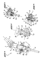
- a coupling device comprises a shaft 1 secured to an upper element 2 of a steering column 3, which is here the lower part 4 of a gimbal 5.
- This shaft 1 can be engaged in a part 6 in the shape of a stirrup secured to a lower element 7 of the steering column 3, which here is a pinion 8 shown in a simplified manner and meshing with a rack, not shown, of a motor vehicle.
- the stirrup 6 has flared ends 6a and 6b arranged in the extension of its sides 11 and 12 allowing easier engagement of the shaft 1 and visible in FIG. 2.
- stirrup-shaped part 6 has two branches 9 and 10 projecting respectively in the extension of the sides 11 and 12 which form the housing 13 receiving the shaft 1.
- These branches transversely comprise a bolt 14 intended to clamp them towards each other in order to block the shaft 1.
- This bolt consists of a first threaded element 15 forming a screw secured to the branch 10 and a second element 16 forming a nut, secured to the branch 9. Note in FIG. 3, representing the threaded element 15 facing the element 16 forming a nut in the waiting position before engagement, that the threaded element 15 cooperates with a ring 17 into which it is screwed. This ring is positively blocked on the branch 10 carrying this element.
- the threaded element 15 is ready to cooperate with the element 16 forming a nut maintained with the element 15 according to a precise axial alignment.
- the ring 17 is housed in a part 18 forming a bridge of substantially cylindrical external shape in which it is made immobile by means of an immobilizing means 19 which is, according to an exemplary embodiment, a lug made of elastic material acting by example by pressure contact on the periphery of the ring 17.
- the part 18 is made integral with the external face of the branch 10 by means of a welded connection 20.
- the ring 17 includes a brake 21, taking the form of an elastomer ring, in engagement with the thread of the element 15 forming a screw.
- This brake 21 keeps the threaded element 15 forming a screw in the ring 17 in its standby position, but also causes the ring 17 to rotate when the element 15 forming a screw cooperates with the element 16 forming a nut.
- the ring 17 is of substantially oval shape in cross section.
- the ring 17 is rotated as explained above and one of its protruding parts 17a or 17b comes into contact against the upper part 1a of the shaft 1 to hold it at the bottom of the stirrup during the blocking phase.
- the shaft 1 is then perfectly positioned in the stirrup 6 and the two elements 4 and 8 are perfectly coaxial.
- the inner part 18a of the trigger guard 18 is a straight groove receiving the ring 17 in a position where the geometric axis 17c of the protruding parts 17a and 17b is always arranged substantially parallel to the geometric axis 1b of the shaft. 1.
- This configuration allows the passage of the ring 17 on the upper part 1a of the shaft 1.
- This groove, as well as the external profile of the part 18 have been shown in dotted lines for a better understanding of the drawings.
- the operation of the coupling device according to the invention is as follows: the shaft 1 is engaged in the housing 13 of the stirrup 6, guided by the free flared ends 6a and 6b.
- the threaded element 15 is pushed by the automatic mounting means, for example a robot, to come into contact with the element 16 forming a nut into which it is then screwed by means of this same mounting means, the ring 17 holding the shaft 1 in position.
- the shaft 1 is made integral with the lower element 7 while the stirrup 6 is made integral with the upper element 5, in particular with the lower part 4 of the gimbal 5.
- FIG 8 there is shown a third embodiment of the coupling device according to the invention.
- the positions of stirrup 6 of shaft 1 have been further modified.
- stirrup 6 is here secured to an upper part 4b of the gimbal 5 now forming the lower element 7 of the steering column 3 while the shaft 1 is made integral with the shaft 3a, now forming the upper element of the steering column 3.
- the trigger guard 18 is produced in the form of a rectangular sheet, shaped then welded on the branch 9, in which the ring 17 is arranged.
- the threaded element 15 is made integral with the branch 9 while the element 16 forming a nut is made integral with the branch 10.
- connection of the element 16 forming a nut on the arms 9 or 10 may be a welded, glued or similar connection, or be an integral part of one of the arms of the stirrup.
- the trigger guard 18 can be fixed on the branch which carries it by means of a welded, glued, or similar connection, or be screwed on the branch which carries it when it is of substantially cylindrical external shape as in the first embodiment of this invention, visible in FIGS. 1 to 4.
- the nut-forming element as well as the trigger guard 18 can be arranged on the inner faces of the branches which carry them if the latter have a recess towards the outside thus increasing the width of the branches.
- the immobilization means 19 can be formed from a rigid material, placed in a housing situated at the periphery of the ring 17, and which can be broken during the movement of this ring.
Landscapes
- Engineering & Computer Science (AREA)
- General Engineering & Computer Science (AREA)
- Mechanical Engineering (AREA)
- Chemical & Material Sciences (AREA)
- Combustion & Propulsion (AREA)
- Transportation (AREA)
- Braking Arrangements (AREA)
- Steering Controls (AREA)
Claims (7)
Applications Claiming Priority (2)
| Application Number | Priority Date | Filing Date | Title |
|---|---|---|---|
| FR8713221 | 1987-09-24 | ||
| FR8713221A FR2620997B1 (fr) | 1987-09-24 | 1987-09-24 | Dispositif d'accouplement pour une colonne de direction et vehicule equipe d'un tel dispositif |
Publications (2)
| Publication Number | Publication Date |
|---|---|
| EP0309344A1 EP0309344A1 (de) | 1989-03-29 |
| EP0309344B1 true EP0309344B1 (de) | 1991-05-08 |
Family
ID=9355186
Family Applications (1)
| Application Number | Title | Priority Date | Filing Date |
|---|---|---|---|
| EP88402379A Expired - Lifetime EP0309344B1 (de) | 1987-09-24 | 1988-09-21 | Verbindungsvorrichtung für eine Lenksäule und ein mit dieser Vorrichtung ausgestattetes Fahrzeug |
Country Status (3)
| Country | Link |
|---|---|
| EP (1) | EP0309344B1 (de) |
| DE (1) | DE3862729D1 (de) |
| FR (1) | FR2620997B1 (de) |
Families Citing this family (13)
| Publication number | Priority date | Publication date | Assignee | Title |
|---|---|---|---|---|
| DE4006787C1 (de) * | 1990-03-03 | 1991-09-19 | Etablissement Supervis, Vaduz, Li | |
| FR2681389B1 (fr) * | 1991-09-13 | 1994-12-23 | Thomson Csf | Dispositif de guidage et de maintien d'une vis impermeable dans un systeme d'assemblage. |
| DE4202684C1 (de) * | 1992-01-31 | 1993-07-29 | Etablissement Supervis, Vaduz, Li | |
| US5984790A (en) * | 1997-08-13 | 1999-11-16 | Nsk Ltd. | Universal joint |
| DE19821646B4 (de) * | 1998-05-14 | 2005-06-16 | ZF Lemförder Metallwaren AG | Befestigungssystem |
| US6350078B1 (en) * | 1999-09-24 | 2002-02-26 | The Torrington Company | Shaft depressor for a slap yoke in a steering assembly |
| US6443650B2 (en) | 2000-02-03 | 2002-09-03 | Nsk Ltd. | Connection structure of lateral insert type yoke and shaft |
| SE525114C2 (sv) | 2002-06-24 | 2004-11-30 | Hemocue Ab | Passiv optisk komponent, samt system och metod för spektrofotometrisk analys som använder en sådan passiv optisk komponent |
| JP2006097884A (ja) | 2004-08-30 | 2006-04-13 | Nsk Ltd | シャフトと自在継手のヨークとの結合部 |
| JP4483485B2 (ja) | 2004-09-01 | 2010-06-16 | 日本精工株式会社 | シャフトと自在継手のヨークとの結合部 |
| DE102005033627A1 (de) * | 2005-07-19 | 2007-01-25 | GM Global Technology Operations, Inc., Detroit | Vorrichtung zur Verbindung einer Zwischenwelle mit einem Ritzel eines Lenkgetriebes |
| JP4735444B2 (ja) * | 2006-07-04 | 2011-07-27 | 日本精工株式会社 | シャフトと自在継手のヨークとの結合部及びその製造方法 |
| JP6514184B2 (ja) * | 2016-12-27 | 2019-05-15 | フタバ産業株式会社 | 車両用の締結構造体 |
Family Cites Families (5)
| Publication number | Priority date | Publication date | Assignee | Title |
|---|---|---|---|---|
| US2948317A (en) * | 1957-07-01 | 1960-08-09 | Gen Electric | Threaded fastener retaining device with resilient holding means |
| BE755157A (fr) * | 1969-11-17 | 1971-02-01 | Pitner Alfred | Assemblage d'un organe d'accouplement et d'un organe transmetteur de couple |
| US4432680A (en) * | 1981-02-23 | 1984-02-21 | Deutsch Fastener Corp. | Stressed panel fastener |
| JPS6085058A (ja) * | 1983-10-17 | 1985-05-14 | Nippon Plast Co Ltd | 分割カバ−の固着装置 |
| JPS60102524U (ja) * | 1983-12-19 | 1985-07-12 | 日産自動車株式会社 | ステアリング装置 |
-
1987
- 1987-09-24 FR FR8713221A patent/FR2620997B1/fr not_active Expired - Fee Related
-
1988
- 1988-09-21 EP EP88402379A patent/EP0309344B1/de not_active Expired - Lifetime
- 1988-09-21 DE DE8888402379T patent/DE3862729D1/de not_active Expired - Fee Related
Also Published As
| Publication number | Publication date |
|---|---|
| EP0309344A1 (de) | 1989-03-29 |
| DE3862729D1 (de) | 1991-06-13 |
| FR2620997B1 (fr) | 1990-02-02 |
| FR2620997A1 (fr) | 1989-03-31 |
Similar Documents
| Publication | Publication Date | Title |
|---|---|---|
| EP0367640B1 (de) | Befestigungsklemme für verschiedene Montagen und beliebige Unterlage, die mit dieser Klemme versehen ist | |
| FR2841871A1 (fr) | Pedale de cycle a positionnement axial reglable | |
| FR2780756A1 (fr) | Systeme de blocage a boulon et ecrou | |
| EP0309344A1 (de) | Verbindungsvorrichtung für eine Lenksäule und ein mit dieser Vorrichtung ausgestattetes Fahrzeug | |
| WO2007113405A1 (fr) | Ecrou pour la fixation d'un pare-brise d'aeronef et dispositif de fixation d'un pare-brise d'aeronef incorporant ledit ecrou | |
| FR2822122A1 (fr) | Assemblage d'un etrier de colonne de direction avec un pignon de direction d'un vehicule automobile | |
| WO2007115622A1 (fr) | Dispositif de serrage | |
| EP0029475A1 (de) | Vorrichtung zum Befestigen oder Sichern eines Gegenstandes auf einem Schaft | |
| EP0086691A1 (de) | Mittel zum Verbinden der Flügel der Kappe der vorderen Übersetzung eines Fahrrads | |
| EP0189216B1 (de) | Webschaft | |
| EP0056228A2 (de) | Steckstift mit einem Kopf und einem Haltering | |
| EP0547945B1 (de) | Torsionsstablager mit Spannringen | |
| EP0112766B1 (de) | Scheibenbremssattel mit entblockbarer Verstärkung | |
| FR2736974A1 (fr) | Attache pour la fixation reglable de deux pieces espacees | |
| EP0802299B1 (de) | Klemm- und Eckverbindungsvorrichtung zwischen zwei rechtwinklig zueinander stehende Metallhohlprofilen | |
| FR2712049A1 (fr) | Dispositif de fixation d'un organe sur un arbre de direction notamment de véhicule automobile. | |
| EP1657085B1 (de) | Vorrichtung zum Verbinden eines Winkelsensors mit einem Stabilisator | |
| FR2733285A1 (fr) | Dispositif de fixation mecanique rigide destine a une rotule, ensemble le comprenant et procedes de montage et demontage | |
| EP0679813B1 (de) | Organ zur mechanischen Befestigung von zwei Elementen aneinander, insbesondere für die Befestigung eines Lenkgetriebegehäuses an einem Lenkgetriebeträger | |
| FR2799515A1 (fr) | Systeme a rattrapage de jeu pour fixer deux pieces l'une a l'autre au moyen d'un organe de fixation du type a vis | |
| EP1104736B1 (de) | Vorrichtung zum Verbinden eines Lenkungsritzels mit einem Bügel | |
| FR3029504A1 (fr) | Attache moteur avant d'aeronef | |
| EP1640620B1 (de) | Vorrichtung zum Befestigen und zum Filtern von Schwingungen und Montageverfahren mit derselben in der Kraftfahrzeugindustrie | |
| EP0754626A1 (de) | Verbindungsvorrichtung zwischen einem rohrförmigen Stab und einem Ankerstück, und deren Anwendung an einer Raumschiffsstruktur | |
| FR2570975A1 (fr) | Outil de serrage manuel. |
Legal Events
| Date | Code | Title | Description |
|---|---|---|---|
| PUAI | Public reference made under article 153(3) epc to a published international application that has entered the european phase |
Free format text: ORIGINAL CODE: 0009012 |
|
| AK | Designated contracting states |
Kind code of ref document: A1 Designated state(s): DE GB IT |
|
| 17P | Request for examination filed |
Effective date: 19890626 |
|
| 17Q | First examination report despatched |
Effective date: 19900612 |
|
| GRAA | (expected) grant |
Free format text: ORIGINAL CODE: 0009210 |
|
| AK | Designated contracting states |
Kind code of ref document: B1 Designated state(s): DE GB IT |
|
| REF | Corresponds to: |
Ref document number: 3862729 Country of ref document: DE Date of ref document: 19910613 |
|
| ITF | It: translation for a ep patent filed | ||
| GBT | Gb: translation of ep patent filed (gb section 77(6)(a)/1977) | ||
| PLBE | No opposition filed within time limit |
Free format text: ORIGINAL CODE: 0009261 |
|
| STAA | Information on the status of an ep patent application or granted ep patent |
Free format text: STATUS: NO OPPOSITION FILED WITHIN TIME LIMIT |
|
| 26N | No opposition filed | ||
| PGFP | Annual fee paid to national office [announced via postgrant information from national office to epo] |
Ref country code: GB Payment date: 19920911 Year of fee payment: 5 |
|
| PGFP | Annual fee paid to national office [announced via postgrant information from national office to epo] |
Ref country code: DE Payment date: 19921005 Year of fee payment: 5 |
|
| PG25 | Lapsed in a contracting state [announced via postgrant information from national office to epo] |
Ref country code: GB Effective date: 19930921 |
|
| GBPC | Gb: european patent ceased through non-payment of renewal fee |
Effective date: 19930921 |
|
| PG25 | Lapsed in a contracting state [announced via postgrant information from national office to epo] |
Ref country code: DE Effective date: 19940601 |
|
| PG25 | Lapsed in a contracting state [announced via postgrant information from national office to epo] |
Ref country code: IT Free format text: LAPSE BECAUSE OF NON-PAYMENT OF DUE FEES;WARNING: LAPSES OF ITALIAN PATENTS WITH EFFECTIVE DATE BEFORE 2007 MAY HAVE OCCURRED AT ANY TIME BEFORE 2007. THE CORRECT EFFECTIVE DATE MAY BE DIFFERENT FROM THE ONE RECORDED. Effective date: 20050921 |