EP0309367A1 - Spender für pastöse Massen mit verbesserter Wirkung und zugehöriges Pumpelement - Google Patents
Spender für pastöse Massen mit verbesserter Wirkung und zugehöriges Pumpelement Download PDFInfo
- Publication number
- EP0309367A1 EP0309367A1 EP88420320A EP88420320A EP0309367A1 EP 0309367 A1 EP0309367 A1 EP 0309367A1 EP 88420320 A EP88420320 A EP 88420320A EP 88420320 A EP88420320 A EP 88420320A EP 0309367 A1 EP0309367 A1 EP 0309367A1
- Authority
- EP
- European Patent Office
- Prior art keywords
- valve
- pumping element
- distributor
- diameter
- pasty product
- Prior art date
- Legal status (The legal status is an assumption and is not a legal conclusion. Google has not performed a legal analysis and makes no representation as to the accuracy of the status listed.)
- Granted
Links
- 238000005086 pumping Methods 0.000 title claims abstract description 64
- 238000003825 pressing Methods 0.000 claims abstract description 5
- 235000011837 pasties Nutrition 0.000 claims description 44
- 238000009826 distribution Methods 0.000 claims description 24
- 230000006835 compression Effects 0.000 claims description 9
- 238000007906 compression Methods 0.000 claims description 9
- 238000003780 insertion Methods 0.000 claims description 9
- 230000037431 insertion Effects 0.000 claims description 9
- 239000000463 material Substances 0.000 claims description 5
- 238000012550 audit Methods 0.000 claims description 3
- 230000003247 decreasing effect Effects 0.000 claims description 3
- 238000007789 sealing Methods 0.000 claims description 3
- 244000043261 Hevea brasiliensis Species 0.000 claims description 2
- 229920003052 natural elastomer Polymers 0.000 claims description 2
- 229920001194 natural rubber Polymers 0.000 claims description 2
- 229920002050 silicone resin Polymers 0.000 claims description 2
- 229920003051 synthetic elastomer Polymers 0.000 claims description 2
- 239000005061 synthetic rubber Substances 0.000 claims description 2
- 229920001169 thermoplastic Polymers 0.000 claims description 2
- 230000000694 effects Effects 0.000 description 10
- 208000031968 Cadaver Diseases 0.000 description 5
- RTZKZFJDLAIYFH-UHFFFAOYSA-N Diethyl ether Chemical compound CCOCC RTZKZFJDLAIYFH-UHFFFAOYSA-N 0.000 description 4
- 229920001903 high density polyethylene Polymers 0.000 description 2
- 239000004700 high-density polyethylene Substances 0.000 description 2
- 229920000728 polyester Polymers 0.000 description 2
- 238000005452 bending Methods 0.000 description 1
- 239000006071 cream Substances 0.000 description 1
- 230000000994 depressogenic effect Effects 0.000 description 1
- 238000007599 discharging Methods 0.000 description 1
- 239000000499 gel Substances 0.000 description 1
- 238000002347 injection Methods 0.000 description 1
- 239000007924 injection Substances 0.000 description 1
- 238000001746 injection moulding Methods 0.000 description 1
- 238000004519 manufacturing process Methods 0.000 description 1
- 238000000034 method Methods 0.000 description 1
- 238000000465 moulding Methods 0.000 description 1
- 239000006072 paste Substances 0.000 description 1
- 230000002093 peripheral effect Effects 0.000 description 1
- 239000004033 plastic Substances 0.000 description 1
- 229920003023 plastic Polymers 0.000 description 1
- 230000001105 regulatory effect Effects 0.000 description 1
- 230000000630 rising effect Effects 0.000 description 1
- 239000000606 toothpaste Substances 0.000 description 1
- 229940034610 toothpaste Drugs 0.000 description 1
Images


Classifications
-
- B—PERFORMING OPERATIONS; TRANSPORTING
- B05—SPRAYING OR ATOMISING IN GENERAL; APPLYING FLUENT MATERIALS TO SURFACES, IN GENERAL
- B05B—SPRAYING APPARATUS; ATOMISING APPARATUS; NOZZLES
- B05B11/00—Single-unit hand-held apparatus in which flow of contents is produced by the muscular force of the operator at the moment of use
- B05B11/01—Single-unit hand-held apparatus in which flow of contents is produced by the muscular force of the operator at the moment of use characterised by the means producing the flow
- B05B11/10—Pump arrangements for transferring the contents from the container to a pump chamber by a sucking effect and forcing the contents out through the dispensing nozzle
- B05B11/1028—Pumps having a pumping chamber with a deformable wall
-
- B—PERFORMING OPERATIONS; TRANSPORTING
- B05—SPRAYING OR ATOMISING IN GENERAL; APPLYING FLUENT MATERIALS TO SURFACES, IN GENERAL
- B05B—SPRAYING APPARATUS; ATOMISING APPARATUS; NOZZLES
- B05B11/00—Single-unit hand-held apparatus in which flow of contents is produced by the muscular force of the operator at the moment of use
- B05B11/01—Single-unit hand-held apparatus in which flow of contents is produced by the muscular force of the operator at the moment of use characterised by the means producing the flow
- B05B11/02—Membranes or pistons acting on the contents inside the container, e.g. follower pistons
- B05B11/028—Pistons separating the content remaining in the container from the atmospheric air to compensate underpressure inside the container
Definitions
- the present invention relates to the field of dispensers for pasty products, comprising a piston sliding in a sealed manner inside a tubular body going towards a dispensing head, as well as pumping means controlled by an actuator and a valve d expulsion or closure of a distribution or exit passage of the pasty product.
- pasty product here designates any product which can be distributed by such a distributor, whether it is described as paste, gel or cream.
- Document FR-A-2557076 describes a dispenser meeting the definition given above, with two embodiments: the first where the bottom piston provided with a non-return metallic skirt moves upward under the effect of the depression caused by the evacuation of the product out of the chamber surmounting this piston, the underside of the piston being at atmospheric pressure and the second where the bottom piston is pulled up step by step, in the direction of the orifice outlet, during successive uses of the dispenser, by a connecting rod coupled to the actuating lever so that the piston rises along the rod each time the latter is depressed.
- the Applicant has found that the effort for dispensing the pasty product (effort to be exerted on the actuator support veil) was too high: 2.5 kg instead of less than 1.5 kg desirable, in this case with a return time to the initial position or cycle time of 2 to 3 seconds, which is acceptable in itself.
- the Applicant has sought to develop a means for reducing the expulsion effort, and secondarily a means for reducing the return time or cycle time of the distributor.
- said upper end of the upper tube of the deformable pumping element consists of an annular end edge and said expulsion valve comprises a flexible disc whose periphery is held in abutment on said end edge of the tubing by a central support means of this disc, this support means being linked to said actuator, said flexible disc and said end edge of the tubing thus constituting respectively the valve and the seat of said expulsion valve .
- the new expulsion valve there is a direct passage of the pasty product between the upper end edge of the pumping element and the periphery of the flexible disc forming a valve, and the height of the peripheral gap of passage obtained for a given expulsion force is a function of the thickness of the flexible disc and of the flexibility of the material of this disc, which makes it possible to modify the opening force or the width of this passage interval, by changing this material and / or by changing this thickness.
- the central support means of the flexible disc is advantageously a longitudinal rod supported by its lower end on the disc or linked to this disc, the top of this rod being held by a centering means carried by the actuator, by example a small tubing of the bottom of the veil of the actuator in which is embedded the top of the rod or reliefs of the same function.
- the flexible disc and its longitudinal support rod are in one piece with the tubular pumping element, typically forming a molded part in a single operation, and the flexible disc is then connected to it.
- the interior of the upper tube by flexible connecting means, for example flexible rods succeeding a short central rod carried by the underside of the disc.
- the arrangement of the flexible connection means is such that the periphery of the flexible disc can be kept in sealed contact with the pasty product on the end edge of its upper tube, acting on its longitudinal support rod.
- the tubular pumping element is in its various presentations preferably in one of the materials of the group formed by: thermoplastic polymers, silicone resins, natural rubber and synthetic rubbers.
- the flexible disk has, outside its central zone carrying the longitudinal support rod and, below, a means of connection to the upper tube, a thickness typically between 0.15 and 0.45 mm.
- the new expulsion valve of the distributor of the invention has been associated with a suction valve described in a French patent application not yet published by the applicant, filed on 10/13/86 under the number n ° 86-14348.
- the tubular body of the dispenser then has a top carrying a passage orifice surrounded by an annular surface constituting the seat of a suction valve for the pasty product in the compression chamber which is delimited by the tubular pumping element, the valve of this valve consisting of an upper web, the annular rim of which is applied in a sealed manner on said annular surface in the closed position of the valve, and an underlying portion engaged in said passage orifice and provided at its lower part with one or more retaining reliefs of overall diameter greater than 0.4 to 2 mm in diameter of said passage orifice.
- the new valve developed, facilitating the suction of the pasty product in the compression chamber, has a surprising influence on the return time or cycle time, as will be seen in the tests.
- the underlying portion of the valve of this new suction valve differs from the corresponding portion of the previous valve in one fundamental point: it has spaced reliefs whose longitudinal outer edges serve as means of guiding the valve in the orifice. passage of the top of the tubular body, these reliefs allowing the passage between them of the pasty product, and the overall diameter of these reliefs being 0.3 to 1.5 mm less than the diameter of said passage orifice.
- the passage of the pasty product through the valve is then multi-radial, whereas in the precise case of the previous valve the product can only pass around the underlying cylindrical portion of the valve, between this portion and the orifice of passage.
- the means for retaining the underlying portion of the valve of the invention preferably consist, in particular for molding, of a substantially circular rod carried by the lower part of the outer edges of the spaced reliefs.
- the upper veil of the valve then comprises a hollow central zone, the underside of this central zone being substantially halfway up the windows for the passage of the pasty product through the valve delimited by the annular edge of the veil of the valve, the spaced reliefs and the circular retaining ring.
- the retaining ring preferably has an outside diameter greater than 0.5 to 1 mm than the diameter of the passage orifice of the top of the tubular body and the longitudinal outer edges of the reliefs spaced from the valve preferably have a smaller overall diameter. from 0.3 to 0.8 mm at this diameter of the passage opening.
- the suction valve As described for the suction valve of EP-A-02130248, the suction valve which has just been described can be injected at the same time as the top of the tubular body on the skirt of this tubular body, the circular rod of the valve being connected to the aperture of the top by a breakable crown of small thickness. This crown is broken after demolding and the circular rod is forced through the passage orifice.
- the sliding piston of which comprises a flexible, flared upper lip sliding inside the skirt of the tubular body, ensuring sealing for the pasty product, a rigid central part recessed by relative to the internal surface of the skirt and a lower flared semi-rigid guide end sliding with a slight play or a slight forcing inside said skirt
- the tubular body preferably comprises means for air leakage during the insertion of said piston into this body until contact with the pasty product contained therein, consisting of a transverse internal relief situated at the bottom of said circular cylindrical skirt and of minimum internal diameter less than 0.3 to 1.5 mm to the inside diameter of said skirt as well as to a flared entry area of this relief of decreasing inside diameter since in engagement diameter at least equal to the outside diameter in the free state of said lip e flexible upper piston until said minimum internal diameter of said relief, the external diameter of said central portion of the piston being less than at least 0.3 mm to said minimum internal diameter of said relief.
- the expulsion valve of the invention has a variety of embodiments, in several pieces or in one piece with the tubular pumping element, and it allows adjustments the opening force or the width of the passage interval of this valve.
- the suction valve which is preferably associated with it makes it possible to surprisingly reduce the time for returning to the rest position of the dispensing head, in particular when the search for a low dispensing force has caused a tubular element to be chosen. low spring effect pumping.
- the first control distributor 1 (FIG. 1), used in the tests (case “a"), firstly comprises a tubular body 2 made of HDPE having a top 3, molded on the cylindrical skirt 4 with an external diameter of 35 mm and 1 mm thick also in HDPE, this apex 3 carrying in its center a central orifice 5 of 22 mm diameter with on the upper periphery of this orifice 5 a planar annular surface 6 serving as a seat for the suction valve 7.
- This valve 7 comprises a sealing veil 8, the annular rim 9 of which is applied in a sealed manner to the annular surface 6, and an underlying cylindrical portion 10 without lateral opening, carrying longitudinal relief reliefs 11 of outside diameter -all 20.5 mm and transverse retaining bosses 12 of circumscribed cylinder diameter 23.5 mm.
- the retaining bosses 12 have been forced through the orifice 5, the valve 7 having been molded at the same time as the crown 3 with a breakable connecting ring, according to the principle commented on below (FIG. 6).
- the axial stroke of the valve 7 in the orifice 5 is 3 mm.
- the deformable tubular pumping element 13 is fixed by its rim lower 14 on the top 3 of the tubular body 2, with clamping between this top 3 and the outer skirt 15 of the actuator 16, the rib 17 of this skirt 15 being snapped into the circular groove 18 of the top 3.
- the actuator 16 comprises a tilting central part 23 connected to its fixed outer skirt 15 by a deformable tab 24 constituting a flexible articulation, and this tilting part 23 itself comprises a support web 25 and, under this web 25, a distribution duct 26 comprising an outlet portion 27 as well as the bottom of a longitudinal chimney 28 carried by the web 25, the outlet duct 27 opening into this chimney 28.
- the upper pipe 21 is fixed in the chimney 28 by the snap-fastening of its outer rib 29 into a groove 30 at the bottom of this chimney 28.
- the flexible upper lip 22 therefore comes to rest in a sealed manner on the underside of the support web 25.
- a cover 31 can be placed on the dispensing head and then rests on a rim of the outer skirt 15.
- the support of the actuator 16 produces: a deformation of the pumping element 13 similar to that of FIG. 5, the closing of the valve 7, as well as a compression of the pasty product contained in the element 13 and its expulsion by passage between the veil 25 and the flexible lip 22, followed by its escape by the outlet duct 27.
- the second control distributor 32 differs from the first distributor 1 only by its actuator 33, described in a French patent application not yet published by the applicant, filed on 23/1/87 under the number 87-01212 .
- the actuator 33 comprises an external tubular part 34 fixed by snap-fastening on the top 3 of the tubular body 2, and an axial pusher 35, initially connected to the tubular part 34 by breakable bridges 36, this pusher 35 being tightly fixed by its chimney 28 to the tubular pumping element 13 as in the first distributor 1.
- the pumping element 13 then constituting elastic means with spring effect which cooperate with the pusher 35 and the tight fixing 28 and 29 allowing the rotation of the chimney 28 around the element 21, the pusher 35 is movable in rotation inside the external tubular part 34 and can slide axially in the positions where this tubular part 34 allows its insertion.
- the distribution duct 26 of the pusher 35 here has an outlet portion 27 with lateral outlet which constitutes its lateral insertion stop, and the external tubular part 34 has three cutouts such as 36 allowing engagement and a selected insertion of the stop lateral 27 and therefore of the plunger 35, as well as an upper edge preventing the plunger from being pushed in when the lateral stop 27 overcomes it.
- the pusher 35 differs from the tilting part 23 of the distributor 1 only by its support veil 37 and its axial driving mode. Its distribution conduit 26 and its chimney 28 as well as its attachment to the pumping element 13 have the same geometry as in the distributor 1, and the skirt 38 for sliding the pusher 35 in the external tubular part 34 does not intervene on the problems studied.
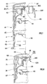
- the first distributor according to the invention 38 differs essentially from the first control distributor 1 only by its pumping element 39, shown separately in FIG. 4 and its suction valve 40.
- the upper tube 41 of the pumping element 39 ends in an annular end edge 42, at right angles to the axis longitudinal of the distributor 38 and of the element 39, edge 42 located just below the interior 43 of the outlet portion 27 of the outlet conduit 26, this end edge 42 constituting the seat of the expulsion valve 42 and 44.
- This valve has for valve a flexible disc 44, of thickness 0.3 mm outside the central zone, disc 44 whose periphery, of outside diameter intermediate between the inside and outside diameters of the end 42 of the upper tube 41 is held in abutment on the edge 42 by the intermediary area of a central longitudinal rod 45, the upper end of which is itself blocked by the underside of the support veil 250 of the actuator 160.
- This support veil 250 carries on its underside a small centering tube 46 in which is embedded the upper end of the central support rod 45.
- the flexible disc 44 and its rod 45 are integral with each other and with the pumping element 39, the underside of the disc 44 being connected to the upper tube 41 by flexible connecting means consisting of a central lug 47 of the underside of the disc 44 and in 3 flexible rods at 120 ° such as 48 and 48 ′ shown incompletely, of cross section 1 x 0.6 mm and inclination 30 ° upwards in the free state ( Figure 4) starting from lug 47 and connecting inside of the tubing 41, just below the end 42 of this tubing.
- the flexible disc 44 As mounted and at rest, that is to say without support from the actuator, the flexible disc 44 is horizontal or barely dug towards its center, and its periphery is in support impervious to the pasty product on the edge of end 42. The operation of this expulsion valve 42 and 44 will be discussed with reference to FIG. 5.
- the suction valve 40 of the distributor 38 differs from the valve 7 or "C1" of the control distributors 1 and 32 by its underlying portion 49 which has 12 reliefs spaced regularly radials such as 50.50 ′, 50 ⁇ , whose longitudinal edges such as 51, with an overall diameter of 21 mm, serve as means for guiding the valve 40 in the orifice 5 with a diameter of 22 mm, as well as a rod 52 retaining a circular contour, supported by the reliefs 50 and of substantially semicircular cross section.
- the obturation veil 53 of the valve 40 has a central hollow area 54, the underside of this area 54 being at an intermediate height of the pasty product passage windows delimited by the annular rim 52, which facilitates the passage of the pasty product through the valve 40 while allowing improved crushing of the pumping element 39 (Figure 5).
- the axial stroke of the valve 40 in the orifice 5 is 3 mm like that of the valve 7.
- the half-figure 5 on the left takes up the arrangement of the complex pumping element 39 and of the valve 40 in FIG. 3: we are at the end of the suction phase, the pumping element 39 has almost resumed its shape initial, pressing on the actuator web 250 being released.
- the periphery of the flexible disc 44 has resumed its shape elastically and is supported on the end 42 of the upper tube 41 of the pumping element 39, closing the top of the pumping or compression chamber 56 delimited by this element of pumping.
- the arrow 57 shows diagrammatically the radial path of the pasty product between two reliefs 50 and 50 ′ then through the opening interval of the annular flange 55 of the valve. Overall, the passage of the pasty product through the central orifice 5 is of the direct multi-radial type.
- the half-figure 5 on the right shows the same pumping element 39 at the end of compression.
- Its deformable veil 20 is folded up as a thermowell between the more rigid lower and upper pipes 41, and its upper fold 58 abuts against the shutter veil 53 of the valve 40, at the top of its hollow central zone 54.
- the geometry of this zone 54 can be modified to allow a more pronounced collapse of the pumping element 39.
- the compression of the chamber 56 produces the expulsion of the pasty product between the end edge 42 of the upper tube 41 and the disc flexible 44 whose periphery curves, expulsion shown diagrammatically by arrow 59.
- the valve 40 is closed, its web 53 being applied by pressure to the annular surface 6.
- FIG. 6 represents the same valve 40, molded at the same time as the rest of the top 3 of the tubular body 2 of the distributor 38 on its cylindrical skirt 4, the bottom of its circular retaining ring being connected to the top of the orifice 5 of the crown 3 by a crown of breakable plastic material 60, about 0.15 mm thick and 0.6 to 0.8 mm wide.
- the pushing of the valve 40 down causes the crown 60 to break and the snap ring 52 to snap below the orifice 5.
- the second distributor according to the invention 61 differs from the first distributor 38 according to the invention (FIG. 3) by its actuator 330 with pusher 350 identical to the actuator of the second indicator distributor 32 (FIG. 2) at l except for a small central tube 46 below the support web 37 of the pusher 350 which holds the central support rod 45 of the flexible disc 44 of the pumping element 39 as in the distributor 38.
- Figure 7 shows the lower part of the tubular body 2, which comprises, at the bottom of the circular cylindrical skirt 4 with an internal diameter of 33 mm, an internal relief 62 with a minimum internal diameter of 32.2 mm, preceded by a flared entry zone 63 of half cone angle of 15 ° and height 4 mm, with an engagement diameter 64 of the flexible upper flared lip 65 of the sliding piston 66 of 34 mm.
- This transverse relief 62 has two effects: escape of the occluded air between the piston 66 and the pasty product during the introduction of the piston 66, as a result of the residual transverse undulation of the flexible lip 65 of the piston 66 due to its constriction of introduction and prohibition of the withdrawal of the piston from below (inviolability).
- Such relief is present in the other distributors according to the invention 38 and 67.
- the third distributor according to the invention 67 differs from the second 61 in that the distribution conduit 68 of its pusher 351 consists essentially of the bottom part of the longitudinal chimney 280 carried by the underside of the support veil 371 of this pusher 351, this veil 371 carrying 6 orifices 69 of 1.5 mm diameter regularly spaced apart, outside the small centering tube 46 and comprised between a circle of diameter 10 mm centered on the longitudinal axis Z and the diameter 13 mm from the bottom of the chimney 280.
- This distributor 67 is used as a fixed or installed distribution pot, actuated with one hand, and in this case the pusher 351 has a lateral insertion stop 70, the cutout 71 of the part outer tubular 34 of the actuator 331 regulating the insertion of this stop 70.
- the control expulsion valve "T” is the valve 22 and 25 or 22 and 37, of the control valves 1 and 32, and the suction valve “C1" is the valve 7 of these distributors tested in the cases “a ".
- the expulsion valve "Inv.” is that 42 and 44 of the first two distributors according to the invention 38 and 61 mounted either with the valve 40 "C2" as in the examples, or with the valve 7 "C1" and with one or the other of two elements pumping tubes 39 of polyester ether having a deformable web thickness 20 respectively 0.9 mm and 0.75 mm.
Landscapes
- Reciprocating Pumps (AREA)
- Pens And Brushes (AREA)
- Coating Apparatus (AREA)
- Transition And Organic Metals Composition Catalysts For Addition Polymerization (AREA)
- Closures For Containers (AREA)
- Die Bonding (AREA)
- Manufacture Of Motors, Generators (AREA)
Priority Applications (1)
| Application Number | Priority Date | Filing Date | Title |
|---|---|---|---|
| AT88420320T ATE61990T1 (de) | 1987-09-25 | 1988-09-22 | Spender fuer pastoese massen mit verbesserter wirkung und zugehoeriges pumpelement. |
Applications Claiming Priority (2)
| Application Number | Priority Date | Filing Date | Title |
|---|---|---|---|
| FR8713927 | 1987-09-25 | ||
| FR8713927A FR2621014B1 (fr) | 1987-09-25 | 1987-09-25 | Distributeur de produit pateux a fonctionnement ameliore et element de pompage correspondant |
Publications (2)
| Publication Number | Publication Date |
|---|---|
| EP0309367A1 true EP0309367A1 (de) | 1989-03-29 |
| EP0309367B1 EP0309367B1 (de) | 1991-03-27 |
Family
ID=9355639
Family Applications (1)
| Application Number | Title | Priority Date | Filing Date |
|---|---|---|---|
| EP88420320A Expired - Lifetime EP0309367B1 (de) | 1987-09-25 | 1988-09-22 | Spender für pastöse Massen mit verbesserter Wirkung und zugehöriges Pumpelement |
Country Status (8)
| Country | Link |
|---|---|
| US (1) | US4962870A (de) |
| EP (1) | EP0309367B1 (de) |
| JP (1) | JPH01111668A (de) |
| AT (1) | ATE61990T1 (de) |
| DE (1) | DE3862183D1 (de) |
| ES (1) | ES2021462B3 (de) |
| FR (1) | FR2621014B1 (de) |
| GR (1) | GR3001674T3 (de) |
Cited By (1)
| Publication number | Priority date | Publication date | Assignee | Title |
|---|---|---|---|---|
| FR2828679A1 (fr) | 2001-08-17 | 2003-02-21 | Cebal | Tube souple a tete distributrice sans retour d'air |
Families Citing this family (12)
| Publication number | Priority date | Publication date | Assignee | Title |
|---|---|---|---|---|
| US5052592A (en) * | 1989-08-14 | 1991-10-01 | Bramlage Gesellschaft Mit Beschrankter Haftung | Dispenser for paste compositions |
| FR2659632B1 (fr) * | 1990-03-14 | 1992-10-16 | Cebal | Distributeur de produit pateux melange d'un produit pateux secondaire et son utilisation. |
| US5253787A (en) * | 1992-08-03 | 1993-10-19 | Package Research Corporation | Fluid dispenser with tiltable dispensing nozzle and sealing membrane |
| US5699934A (en) * | 1996-01-29 | 1997-12-23 | Universal Instruments Corporation | Dispenser and method for dispensing viscous fluids |
| DE20201742U1 (de) * | 2002-02-05 | 2003-03-20 | RPC Wiko GmbH & Co. KG, 50259 Pulheim | Spender für fließfähige Produkte |
| DE102008029004A1 (de) * | 2007-06-29 | 2009-01-02 | Rpc Bramlage Gmbh | Spender zur Ausgabe flüssiger oder pastöser Massen |
| FR2919589B1 (fr) * | 2007-08-01 | 2009-11-13 | Airlessystems Soc Par Actions | Clapet d'obturation et procede pour fabriquer un tel clapet. |
| US8640926B2 (en) | 2010-11-04 | 2014-02-04 | Gojo Industries, Inc. | Dispenser with flexible cover |
| IT1406090B1 (it) * | 2011-02-22 | 2014-02-06 | Taplast Srl | Dispositivo per l'erogazione di fluidi o miscele. |
| US9555428B2 (en) * | 2011-02-22 | 2017-01-31 | Taplast S.P.A. | Device for dispensing fluids or mixtures |
| CN114521185B (zh) * | 2019-07-23 | 2024-08-06 | 里克包装系统有限公司 | 具有内部塞件密封的全聚合物泵分配器 |
| IT202000025597A1 (it) * | 2020-10-28 | 2022-04-28 | Guala Dispensing Spa | Dispenser per prodotti pastosi con valvola di mandata |
Citations (6)
| Publication number | Priority date | Publication date | Assignee | Title |
|---|---|---|---|---|
| US2774517A (en) * | 1955-09-19 | 1956-12-18 | James E Teegardin | Fluid dispenser device |
| FR2350278A1 (fr) * | 1976-05-03 | 1977-12-02 | Wischerath Kg Josef | Tube a coulisse pour produit en baton |
| FR2581370A1 (fr) * | 1985-05-06 | 1986-11-07 | Cebal | Distributeur pour produits pateux |
| EP0213048A1 (de) * | 1985-07-24 | 1987-03-04 | Cebal | Spender für pastöse oder sahnige Produkte |
| EP0221362A2 (de) * | 1985-11-06 | 1987-05-13 | F.P.D. Future Patents Development Company S.A. | Spender für pastöse Massen |
| EP0266284A1 (de) * | 1986-10-13 | 1988-05-04 | Cebal | Spender für Pasteten-Produkte und Verfahren zur Fabrikation |
Family Cites Families (8)
| Publication number | Priority date | Publication date | Assignee | Title |
|---|---|---|---|---|
| US3244332A (en) * | 1964-11-18 | 1966-04-05 | Howard L Rogers | Self-closing cap |
| US3752366A (en) * | 1971-10-27 | 1973-08-14 | W Lawrence | Two-piece suction pump |
| US3874563A (en) * | 1973-06-19 | 1975-04-01 | Gilbert Schwartzman | Applicator having multiple valve assemblies |
| US3986644A (en) * | 1975-05-21 | 1976-10-19 | Diamond International Corporation | Dispensing pump |
| JPS5393961A (en) * | 1977-01-27 | 1978-08-17 | Hiroshige Ishikawa | Cushion suitable for beauty and health |
| US4201317A (en) * | 1977-07-28 | 1980-05-06 | Aleff Hans P | Finger actuated pump assembly |
| DE3035742A1 (de) * | 1980-09-22 | 1982-05-13 | Henkel KGaA, 4000 Düsseldorf | Klappenventil |
| EP0144879B1 (de) * | 1983-12-02 | 1988-10-12 | Bramlage GmbH | Spender für pastöse Massen, Insbesonder Zahncremespender |
-
1987
- 1987-09-25 FR FR8713927A patent/FR2621014B1/fr not_active Expired
-
1988
- 1988-09-21 JP JP63237470A patent/JPH01111668A/ja active Pending
- 1988-09-22 ES ES88420320T patent/ES2021462B3/es not_active Expired - Lifetime
- 1988-09-22 EP EP88420320A patent/EP0309367B1/de not_active Expired - Lifetime
- 1988-09-22 AT AT88420320T patent/ATE61990T1/de not_active IP Right Cessation
- 1988-09-22 DE DE8888420320T patent/DE3862183D1/de not_active Expired - Lifetime
- 1988-09-22 US US07/247,502 patent/US4962870A/en not_active Expired - Fee Related
-
1991
- 1991-03-28 GR GR90401137T patent/GR3001674T3/el unknown
Patent Citations (6)
| Publication number | Priority date | Publication date | Assignee | Title |
|---|---|---|---|---|
| US2774517A (en) * | 1955-09-19 | 1956-12-18 | James E Teegardin | Fluid dispenser device |
| FR2350278A1 (fr) * | 1976-05-03 | 1977-12-02 | Wischerath Kg Josef | Tube a coulisse pour produit en baton |
| FR2581370A1 (fr) * | 1985-05-06 | 1986-11-07 | Cebal | Distributeur pour produits pateux |
| EP0213048A1 (de) * | 1985-07-24 | 1987-03-04 | Cebal | Spender für pastöse oder sahnige Produkte |
| EP0221362A2 (de) * | 1985-11-06 | 1987-05-13 | F.P.D. Future Patents Development Company S.A. | Spender für pastöse Massen |
| EP0266284A1 (de) * | 1986-10-13 | 1988-05-04 | Cebal | Spender für Pasteten-Produkte und Verfahren zur Fabrikation |
Cited By (2)
| Publication number | Priority date | Publication date | Assignee | Title |
|---|---|---|---|---|
| FR2828679A1 (fr) | 2001-08-17 | 2003-02-21 | Cebal | Tube souple a tete distributrice sans retour d'air |
| WO2003016159A2 (fr) | 2001-08-17 | 2003-02-27 | Cebal S.A.S. | Tube souple a tete distributrice sans retour d'air |
Also Published As
| Publication number | Publication date |
|---|---|
| FR2621014A1 (fr) | 1989-03-31 |
| FR2621014B1 (fr) | 1989-11-24 |
| ES2021462B3 (es) | 1991-11-01 |
| EP0309367B1 (de) | 1991-03-27 |
| DE3862183D1 (de) | 1991-05-02 |
| ATE61990T1 (de) | 1991-04-15 |
| JPH01111668A (ja) | 1989-04-28 |
| US4962870A (en) | 1990-10-16 |
| GR3001674T3 (en) | 1992-11-23 |
Similar Documents
| Publication | Publication Date | Title |
|---|---|---|
| EP0623060B1 (de) | Vordruckpumpe | |
| EP0816253B1 (de) | Vorrichtung und Verfahren zur getrennten Aufbewahrung von mindestens zwei Produkten, zur deren Mischung sowie zur Abgabe dieser Mischung | |
| EP0888823B1 (de) | Pumpanordnung enthaltender Spender für pastöses oder flüssiges Material | |
| EP0410858B1 (de) | Abgabevorrichtung für wenigstens ein flüssiges Produkt, insbesondere kosmetischer oder pharmazeutischer Art | |
| EP0309367B1 (de) | Spender für pastöse Massen mit verbesserter Wirkung und zugehöriges Pumpelement | |
| EP0939039A1 (de) | Ausgabekopf zur Ausgabe eines Stoffs sowie eine mit einem solchen Ausgabekopf versehene Ausgabevorrichtung | |
| FR2626851A1 (fr) | Dispositif pour faciliter le remplissage des vaporisateurs | |
| EP0905052B1 (de) | Aufbewahrungs- und Ausgabevorrichtung für flüssige oder halbflüssige Produkte | |
| EP1701799B1 (de) | Flüssigkeitsspendereinheit und behälter mit einer solchen einheit | |
| EP0329582B1 (de) | Spender für pastöse Produkte, versehen mit einem zur seitlichen Ausgabe dienenden axialen Betätigungskopf, und Verhüllungselement für seine Ausgabeöffnung | |
| EP0477083B1 (de) | Vordruck-Handpumpe | |
| EP0266284B1 (de) | Spender für Pasteten-Produkte und Verfahren zur Fabrikation | |
| EP1038799A1 (de) | Aerosoldose mit gegossene fliegendem Kolben und Verfahren zur Herstellung desselben | |
| EP1814672A1 (de) | Ein auslassventil und eine rückstellfeder für eine abgabevorrichtung bildendes flexibles teil | |
| FR2710036A1 (fr) | Conditionnement composé d'un récipient rigide à l'intérieur duquel est monté un récipient déformable contenant un produit délivré par doses à l'aide d'une pompe. | |
| EP2178649B1 (de) | Ausgabeelement für ein flüssigprodukt | |
| EP0277893A1 (de) | Spender für pastöse Produkte mit drehbarem Druckknopf | |
| EP1262241B1 (de) | Membranpumpe und damit ausgerüsteter Behälter | |
| EP1074479B1 (de) | Membranpumpe für Behälter | |
| EP0213048A1 (de) | Spender für pastöse oder sahnige Produkte | |
| FR2708314A1 (fr) | Perfectionnements aux pompes doseuses. | |
| FR2746076A1 (fr) | Dispositif d'obturation et de prelevement controle de produit fluide pour recipient de stockage et recipient equipe d'un tel dispositif | |
| FR2974792A1 (fr) | Distributeur de produit fluide. | |
| FR3113253A1 (fr) | Assemblage d’une membrane souple de pompage et d’un embout rigide d’une pompe d’un systeme de distribution sans air d’un produit liquide ou pateux |
Legal Events
| Date | Code | Title | Description |
|---|---|---|---|
| PUAI | Public reference made under article 153(3) epc to a published international application that has entered the european phase |
Free format text: ORIGINAL CODE: 0009012 |
|
| AK | Designated contracting states |
Kind code of ref document: A1 Designated state(s): AT BE CH DE ES FR GB GR IT LI LU NL SE |
|
| 17P | Request for examination filed |
Effective date: 19890410 |
|
| 17Q | First examination report despatched |
Effective date: 19900827 |
|
| GRAA | (expected) grant |
Free format text: ORIGINAL CODE: 0009210 |
|
| AK | Designated contracting states |
Kind code of ref document: B1 Designated state(s): AT BE CH DE ES FR GB GR IT LI LU NL SE |
|
| REF | Corresponds to: |
Ref document number: 61990 Country of ref document: AT Date of ref document: 19910415 Kind code of ref document: T |
|
| GBT | Gb: translation of ep patent filed (gb section 77(6)(a)/1977) | ||
| REF | Corresponds to: |
Ref document number: 3862183 Country of ref document: DE Date of ref document: 19910502 |
|
| ITF | It: translation for a ep patent filed | ||
| PGFP | Annual fee paid to national office [announced via postgrant information from national office to epo] |
Ref country code: ES Payment date: 19910705 Year of fee payment: 4 |
|
| PGFP | Annual fee paid to national office [announced via postgrant information from national office to epo] |
Ref country code: GR Payment date: 19910729 Year of fee payment: 4 |
|
| PGFP | Annual fee paid to national office [announced via postgrant information from national office to epo] |
Ref country code: AT Payment date: 19910814 Year of fee payment: 4 |
|
| PGFP | Annual fee paid to national office [announced via postgrant information from national office to epo] |
Ref country code: SE Payment date: 19910816 Year of fee payment: 4 Ref country code: DE Payment date: 19910816 Year of fee payment: 4 |
|
| PGFP | Annual fee paid to national office [announced via postgrant information from national office to epo] |
Ref country code: CH Payment date: 19910819 Year of fee payment: 4 |
|
| PGFP | Annual fee paid to national office [announced via postgrant information from national office to epo] |
Ref country code: LU Payment date: 19910828 Year of fee payment: 4 |
|
| PG25 | Lapsed in a contracting state [announced via postgrant information from national office to epo] |
Ref country code: BE Effective date: 19910930 |
|
| PGFP | Annual fee paid to national office [announced via postgrant information from national office to epo] |
Ref country code: NL Payment date: 19910930 Year of fee payment: 4 |
|
| EPTA | Lu: last paid annual fee | ||
| PLBE | No opposition filed within time limit |
Free format text: ORIGINAL CODE: 0009261 |
|
| STAA | Information on the status of an ep patent application or granted ep patent |
Free format text: STATUS: NO OPPOSITION FILED WITHIN TIME LIMIT |
|
| 26N | No opposition filed | ||
| BERE | Be: lapsed |
Owner name: CEBAL Effective date: 19910930 |
|
| REG | Reference to a national code |
Ref country code: FR Ref legal event code: TP |
|
| REG | Reference to a national code |
Ref country code: GR Ref legal event code: FG4A Free format text: 3001674 |
|
| PG25 | Lapsed in a contracting state [announced via postgrant information from national office to epo] |
Ref country code: LU Free format text: LAPSE BECAUSE OF NON-PAYMENT OF DUE FEES Effective date: 19920922 Ref country code: GB Effective date: 19920922 Ref country code: AT Effective date: 19920922 |
|
| PG25 | Lapsed in a contracting state [announced via postgrant information from national office to epo] |
Ref country code: SE Effective date: 19920923 Ref country code: ES Free format text: LAPSE BECAUSE OF EXPIRATION OF PROTECTION Effective date: 19920923 |
|
| PG25 | Lapsed in a contracting state [announced via postgrant information from national office to epo] |
Ref country code: LI Effective date: 19920930 Ref country code: CH Effective date: 19920930 |
|
| PG25 | Lapsed in a contracting state [announced via postgrant information from national office to epo] |
Ref country code: GR Free format text: THE PATENT HAS BEEN ANNULLED BY A DECISION OF A NATIONAL AUTHORITY Effective date: 19930331 |
|
| PG25 | Lapsed in a contracting state [announced via postgrant information from national office to epo] |
Ref country code: NL Effective date: 19930401 |
|
| NLV4 | Nl: lapsed or anulled due to non-payment of the annual fee | ||
| GBPC | Gb: european patent ceased through non-payment of renewal fee |
Effective date: 19920922 |
|
| REG | Reference to a national code |
Ref country code: CH Ref legal event code: PL |
|
| PG25 | Lapsed in a contracting state [announced via postgrant information from national office to epo] |
Ref country code: DE Effective date: 19930602 |
|
| REG | Reference to a national code |
Ref country code: GR Ref legal event code: MM2A Free format text: 3001674 |
|
| EUG | Se: european patent has lapsed |
Ref document number: 88420320.9 Effective date: 19930406 |
|
| REG | Reference to a national code |
Ref country code: ES Ref legal event code: FD2A Effective date: 19990601 |
|
| PGFP | Annual fee paid to national office [announced via postgrant information from national office to epo] |
Ref country code: FR Payment date: 20010913 Year of fee payment: 14 |
|
| PG25 | Lapsed in a contracting state [announced via postgrant information from national office to epo] |
Ref country code: FR Free format text: LAPSE BECAUSE OF NON-PAYMENT OF DUE FEES Effective date: 20030603 |
|
| REG | Reference to a national code |
Ref country code: FR Ref legal event code: ST |
|
| PG25 | Lapsed in a contracting state [announced via postgrant information from national office to epo] |
Ref country code: IT Free format text: LAPSE BECAUSE OF NON-PAYMENT OF DUE FEES;WARNING: LAPSES OF ITALIAN PATENTS WITH EFFECTIVE DATE BEFORE 2007 MAY HAVE OCCURRED AT ANY TIME BEFORE 2007. THE CORRECT EFFECTIVE DATE MAY BE DIFFERENT FROM THE ONE RECORDED. Effective date: 20050922 |