EP0309397B2 - Sanitäre Wasseranschlussanordnung - Google Patents
Sanitäre Wasseranschlussanordnung Download PDFInfo
- Publication number
- EP0309397B2 EP0309397B2 EP88810601A EP88810601A EP0309397B2 EP 0309397 B2 EP0309397 B2 EP 0309397B2 EP 88810601 A EP88810601 A EP 88810601A EP 88810601 A EP88810601 A EP 88810601A EP 0309397 B2 EP0309397 B2 EP 0309397B2
- Authority
- EP
- European Patent Office
- Prior art keywords
- housing
- valve
- connection
- arrangement according
- pipe
- Prior art date
- Legal status (The legal status is an assumption and is not a legal conclusion. Google has not performed a legal analysis and makes no representation as to the accuracy of the status listed.)
- Expired - Lifetime
Links
Images


Classifications
-
- E—FIXED CONSTRUCTIONS
- E03—WATER SUPPLY; SEWERAGE
- E03C—DOMESTIC PLUMBING INSTALLATIONS FOR FRESH WATER OR WASTE WATER; SINKS
- E03C1/00—Domestic plumbing installations for fresh water or waste water; Sinks
- E03C1/02—Plumbing installations for fresh water
- E03C1/04—Water-basin installations specially adapted to wash-basins or baths
- E03C1/042—Arrangements on taps for wash-basins or baths for connecting to the wall
-
- E—FIXED CONSTRUCTIONS
- E03—WATER SUPPLY; SEWERAGE
- E03C—DOMESTIC PLUMBING INSTALLATIONS FOR FRESH WATER OR WASTE WATER; SINKS
- E03C1/00—Domestic plumbing installations for fresh water or waste water; Sinks
- E03C1/02—Plumbing installations for fresh water
- E03C1/021—Devices for positioning or connecting of water supply lines
Definitions
- the present invention relates to a sanitary water connection arrangement according to the preamble of independent claim 1.
- the generic EP-B-119 960 known armature connection member provided a so-called battery piece, which the disordered supply lines according to the definition in claim 1 arranged offset to one another in the axial direction are.
- the fitting engages in the hole in the battery piece. If either in the valve or in the Battery piece two parallel circumferential grooves each communicating with an inflow line are provided, the valve can be used in any rotational position with regard to the battery piece. But if hot and cold water supply the part of the valve that dips into the hole must be separated from it, to make it possible to change the plug.
- the insert part with its axial bores is very expensive in production, so that it hardly arouses great interest in new installation technology can.
- This conventional assembly is opposed to the so-called chaotic assembly, for example Due to structural reasons it is not possible to arrange the supply lines for hot and cold water supply, or in old buildings, in which due to the old separate taps, the connections must be made in an orderly manner are. Therefore, an adjustment or even change should be possible.
- the connector itself is only designed for an end connection of the two water pipes and not intended for the passage of two water pipes. However, this connector shows one central connection, which communicates with the one water pipe and a ring channel leading around it, who communicates with the other water pipe. This ensures that the valve is in position.
- a disadvantage of the proposed solution is that the position of the fitting is only corrected via the thread can be used, so that only a very specific type of fittings can be used. Correcting the thickness of the Plastering can also only be corrected by screwing it in more or less deep, which is the case with such Diameter of the screw parts is difficult. Furthermore, none can be arranged with such an arrangement Install filter or backflow preventer or other additional elements.
- DE-A-17 24 793 shows an arrangement which is very similar to that according to DE-A-18 11 936, but in which the housing of the fitting is connected to the connecting piece via a connecting threaded tube.
- connection device for mixing fittings has become known, which has a fitting, which has comparatively complex channels and can be rotated around a connection to correct.
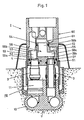
- FIGS. 1 to 5 are not covered by claim 1 and serve only for explanation.
- connection pieces 12, 12 'and 13, 13' are arranged parallel to one another in the connecting part 10.
- the connecting pieces 12, 12 'on the one hand and 13, 13' on the other hand form two separate pipe connections.
- a branch line 14, 15 is branched off from each of these pipe connections, the axes of which are perpendicular to the plane of the pipe connection and are arranged parallel to the axis of the cylindrical base part 11.
- Any known single or multi-lever mixer can be used as a fitting.
- FIG Embodiments drawn For the rigid connection between the valve housing 21 and the base part 11, two different ones are shown in FIG Embodiments drawn.
- a union nut 16a by means of a Threaded ring 17 held captive on the base part 11.
- the uebrew mother carries 16a a thread with which it is screwed onto the housing of the fitting 2.
- the stop for the screw-in depth of the union nut 16a is given by the length of the nipples 3, 3 ', which engage with their cylindrical pin 32 in an insertion opening and abut there.
- CH-A-381 170 are nipples for connecting a flush-mounted connector to a valve known. Only the nipples have a bead with the known, with which a support plate to the Wall is used. The fitting is attached to the support plate using a union nut. As a result, the nipples are permanently loaded and could therefore change structurally. Serve against it the nipple according to the present invention only the adjustable adjustment of the valve. The force fit occurs between the housing of the valve and the connection housing.
- connection housing 1 can be covered with a plastic protective sleeve 18, which is used to keep the space required for fastening the fitting can be designed in a known manner as a cap, to be cut off after pouring.
- the second embodiment for the union nut 16b is shown on the right in FIG.
- the only difference The first embodiment described above is that it does not have a threaded ring is held on the connection housing 1, but with a second thread. If the top thread is one has a smaller pitch than the lower thread, e.g. 2 mm and 1.5 mm, the armature 2 for Be brought stop between the sleeves 30 and the pin 32 as long as the union nut 16b is screwed to it.
- This distributor 4 is thus provided with plug sockets 30, 30 'for the nipples 3, 3', which are also the Make stops for the insertion depth. From the outside, the distributor 4 consists of a base cylinder 53 and a plug-in cylinder 54 for the connection to the fitting 2, which will be discussed later.
- the two cylinders 53, 54 differ in diameter, the base cylinder 53 being one has a larger diameter than the insertion cylinder 54.
- the passages within the distributor 4 are simple axial bores, one of which is a passage 59 in the shoulder surface 55, as the top surface of the base cylinder 53, opens as an opening 59b and between the corresponding plug-in socket 30, 30 'and this opening as an axially parallel bore and the other passage 58 is composed of two bores 58a, 58b, one of which in the base part 53 eccentrically but axially parallel and that in the insert cylinder 54 are coaxial and themselves overlap at least partially and form a free passage.
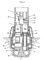
- no backflow preventers are provided. But these can be in the simplest way according to the embodiment of Figure 2 can be installed in the distributor 4 by the additional length of the two cavities 58c, 59c is extended.
- the housing must of course also be used 21 of the armature 2 can be extended by the same amount.
- the remaining parts such as connection housing 1, nipple 3, 3 'and armature 2 are the same as in the previously described exemplary embodiments.
- Another advantage of this invention is the fact that instead of the nipples 3, 3 'plugs for pressing of the lines or ventilation valves can be screwed in, so that the entire pre-installation is feasible.
- connection housing 1 with the connection part 10 and a cylindrical Housing part 11 recognizable.
- connecting part 10 On the connecting part 10 there are again two pairs of connecting pieces 12, 12 'and 13, 13' arranged in parallel to each other.
- An eccentric, axially parallel bore is arranged above the pair 12, 12 ', which leads into the connecting piece connection penetrates and so forms a stub 15.
- a central bore 117 is in the housing part 11 present, which has a radius that is the distance between the axis of the housing part 11 and the extreme peripheral point of the stub 15 corresponds, or as shown in Fig.3, slightly larger than this Distance is. From the bottom 119 of this central bore 117 there is a blind hole 14 between the two pairs the connecting piece 12, 12 '13, 13' drilled, which the wall of the second pair of connecting pieces 13, 13 ' breaks through and thus creates a radial stub.
- a cylindrical recess 116 is formed centrally in the bottom 119 in the central bore 117 is located above the blind hole 14 and serves as a seat for a pipe section 105.
- connection part of the fitting which is the connection to the second feed hole 126.
- the line 127 is shown for connection for mixed water.
- a union nut 129 is caught on the connection housing 1 with a threaded ring 118 and is open a thread 128 is screwed to the housing 21, so that the housing 21 and the connection housing 1 are rigid are interconnectable.
- valve can be precisely positioned even with inaccurately laid conduits Alignment to be corrected.
- this can result in the swapping of hot and cold water pipes cannot be undone.
- an additional element according to FIG. 4 is used instead of the pipe section 105 in Fig.3 required.
- This distributor 4 is in the central bore 117 in the connection housing 1 and in the central bore 122 used in the housing 21 of the armature 2.
- the distributor 4 engages in the cylindrical recess on the one hand 116 in the connection part 10 of the connection housing 1 and on the other hand into the bore 123 in the housing 21 a.
- a radial flange 142 bears sealingly against the wall of the central bore 122 of the housing 21 and divides the ring channel in Figure 3 into an annular channel 143 in the connection housing 1 and an annular channel 144 in Housing 21.
- the axially parallel lines 145, 146 and radial openings 147, 148 separate the two ring channels 143, 144 connected to the respective connector 140, 141 located at the opposite end of the distributor 4. This means that the connection paths according to FIG. 3 are interchanged.
- a union nut 129 which is caught on the connection housing, for fastening the valve 2 on the connection housing 1 must be provided to the two parts, the pipe section 105 or to keep the distributor 4 interchangeable, can be an adjustment of the distance from the wall surface cannot be made possible without additional funds.
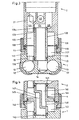
- FIG. 5 Such an arrangement for setting both conventional precise installation and chaotic Installation with adjustment of the wall distance is shown in Fig. 5. Although only the execution here is shown with a distributor, this distributor could of course also by a piece of pipe according Fig.3 to be replaced.
- the changes compared to the explanations according to FIGS. 3 and 4 thus relate to an extension of the cylindrical recess 116 in Figures 3 and 4, an extension of the lower neck of the distributor 4 and an extension engaging in the central bore 117 in the connection housing 1 the wall of the housing 21.
- connecting part 10 with four pipe sockets 12, 12 '13, 13 'provided, which are arranged in pairs parallel to each other in a row.
- neck Above this neck there is a cylindrical base part 11 with an axial main bore 218.
- the one connecting piece pair 13, 13 ' is open to the main bore 218 with a first stub 15.
- the other connection pipe pair 12, 12 ' is cut with a second stub 14, so that a passage 19 is radial Direction in the main bore 218 results.
- a cylindrical distributor 4 is rotatably inserted into the main bore 218.
- This distributor 4 has one pierced pin 221, which is sealingly inserted into the second stub 14.
- One across from the front edge 222 of the pin 221 set back surface 223 forms with the bottom 217 of the main bore 218 together an annular channel 224 leading around the pin 221.
- An axially parallel first passage 225 in the distributor 4 communicates with the first stub 15 in Connecting part 11 and a second passage 226 diametrically opposite this stub 15 communicates with a coaxial bore 227 in the pin 221 via a connection 226 '. Centric between the Mouths of the passages 225, 226 there is an axial bore 228.
- the distributor 4 is held in the housing part 11 by means of a holding plate 229.
- This holding plate 229 in turn is rigidly held by means of three screws 230 which are screwed into peripheral eyes 216 on the housing part 11.
- it has a central position another threaded bore 233 aligned with bore 228.
- connection housing 1 can be dismantled and, provided that the screw-in depth of the bolt 246 does not change it can be put back on and fastened after any repairs have been made.
- the Water-carrying parts, namely the distributor 4 and the nipples 3, 3 ', are not under load.
- the Krafl River arrives from the bolt 246 to the holding plate 229 and via the screws 230 into the connection housing 1.
- Two are used for the basic setting of the screwing depth of the stud screw 246 into the holding plate 229 or one or more spacer rings 234, 235, of which one spacer ring 234 on the valve housing 21 the fitting 2 is screwed on.
- exemplary embodiments for fittings with a mixed water line are provided for direct outlet from the fitting, have the following exemplary embodiments according to Fig. 9 to 17 mixed water pipes, which via the plastered connection housing, to a shower and / or a bath water inlet.
- DE-A-35 19 652 provides an arrangement with an additional connection piece for mixed water, however, four valves are arranged in the connection housing, two of which each have an outlet at the end Communicate the hole on the one hand and the continuous cold or hot water channel on the other.
- the two holes are aligned with further holes in a distributor on which the Mixer tap is attached.
- Cold or warm water can be supplied to the two holes so that a wrong connection to the connecting piece can be corrected.
- This is special Useful if fittings are connected to the same pipes on both sides of the wall should be.
- this known arrangement requires that the cold and hot water pipes run horizontally. This makes complex installations required.
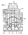
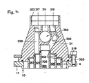
- a further embodiment for a connection arrangement for a mixing valve is in section in FIG shown. It comprises a sub-concealed connection housing 1 with a cold water pipe and one Hot water pipe with one connection piece 12, 12 ', 13, 13' (Fig.11), so that the connection housing 1 can be used in continuous lines. Transversely to the connection piece pairs 12, 12 ', 13, 13' two mixed water connecting pieces 306, 307 are arranged. Perpendicular to the level of the connection pipe pairs 12, 12 ', 13, 13', coaxial, cylindrical bores 308 are machined in the connection housing. Coaxial a valve housing 21 is fastened to the bores 308 on the connection housing 1 by means of screws 323.
- the screw head presses a collar 319 of the valve housing 21 against the connection housing 1 and is supported on the outside by a ring 320. This allows the valve body 21 to be around turn its axis in relation to the connection housing 1 and fix it with the screws 323.
- the valve housing 21 has a threaded bore 322 with a flat base 323 for inserting a mixing valve, not shown.
- a mixing valve not shown.
- the base area 323 three axially parallel Holes 316, 317.318 for hot water, cold water and mixed water, with corresponding holes the mixer tap.
- a distributor 4 is used, which in the Embodiment according to Figure 9 consists of two coaxial tubes 326, 327. These enclose together with the outermost bore 308 three coaxial ring channels 328, 329, 330. These ring channels connect passages 333, 334 or stub lines 14, 15 of the connection housing 1 with passages 335, 336, 337 of Fitting housing 21, which are each connected to one of the bores 316, 317, 318.
- Passages 333, 334 and branch lines 14, 15 open into the coaxial bores at different radial distances 308 and connect the three ring channels 328, 329, 330 to the connecting piece pairs 12, 12 ', 13, 13', wherein the outermost ring channel 330 is connected to both mixed water connecting pieces 306, 307.
- the distributor 4 is opposite on both sides by two concentric O-rings 338 of different diameter Fitting housing 21 or the connection housing 1 sealed.
- the inner tube 326 of the distributor 4 is exchanged for a distributor 4, according to FIG. 10.
- the distributor 4 seals with a flange 344 and an O-ring 345 in the tube 327.
- the two passages 328, 329 connect the passages 331 and 336 or 332 and 335 to one another here, so that cold and Hot water swapped over to the variant according to Fig. 9 reaches the mixer tap.
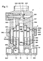
- Connection housing 1 also has a shuttle valve 352 installed.
- this valve 352 the mixed water can optionally via one of the two outlets 353, 354 one of the two mixed water connections 306, 307, e.g. for connecting a bath spout or a shower. Otherwise this corresponds Embodiment of that according to FIG. 9.
- the shuttle valve 352 is arranged in the valve housing 21.
- the distributor 4 has a further coaxial tube 357, which has the two outlets 353, 354 of the valve 352 separates from each other, so that they are each connected to one of the mixed water connecting pieces 306, 307 are.
- the two channels 333, 334 of the connection housing 1 open in different radial Distances in one of the coaxial bores 308.
- the embodiment corresponds to FIG. 13 and 14 those according to Fig.12.
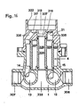
- FIG. 15 A further variant of the embodiment according to FIGS. 13 and 14 is shown in FIG. 15, in which the Fitting housing 21 can be rotated relative to the connection housing 1 as well as being continuously axially displaceable and is noticeable.
- the valve housing 21 has a tubular extension 360, which is in the outermost one Bore 308 of the connection housing 1 longitudinally displaceable and rotatable and with another O-ring 361 is sealed.
- a clamped on the shoulder 360, conical on both sides, is used for clamping tapered, slotted ring 362. This is in corresponding conical surfaces of a flange 363 of the Connection housing 1 and a ring 364 used.
- the ring 364 is countered by the screws 323 pulled the flange 363 and thereby presses the ring 362 radially against the shoulder 360.
- the tubes 326, 327, 357 of the distributor 4 are connected here by axially parallel ribs 365 and engage in coaxial, tubular lugs 366 rigidly connected to the connection housing 1.
- the innermost tube 326 is over a thread 367 is screwed into the valve housing 21. Otherwise, the embodiment corresponds to Fig. 15 that according to Fig. 13 and 14.
- the embodiment according to FIG. 16 differs from that according to FIG. 9 by a different arrangement of the passages.
- the housing bore 318 for mixed water is here via the central ring line 328 of the distributor 4 with the common passage 333 connecting the mixed water connections 306, 307 connected in the connection housing 1.
- Cold and hot water are connected to the two ring channels 329, 330 Bores 316, 317 out.
- the embodiment according to FIG. 16 corresponds to that according to FIG. 9.
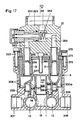
- valve housing 21 is opposite the connection housing 1 as in the example of FIG. 15, both rotatable and axially steplessly displaceable.
- the distributor As in the embodiment according to FIG. 13, 4 is in coaxial cylindrical bores 308 of the connection housing 1 with cylindrical lugs 371 used sealing.
- the distributor is on the opposite end 4 flat and is rotatable against one by means of screws 372 and a washer 373 on the connection housing 1 attached washer 374.
- the disk 374 has four eccentric through holes 375 which align with axially parallel holes 376 in the distributor 4. Each of the holes 376 communicates with one the ring channels 328, 329, 330, 330a.
- valve body 21 Longitudinally displaceable in the bores 376, sealed by O-rings 377, into the fitting housing 21 screwed nipples 3, 3 '.
- the valve body 21 is through the Screws 323 over a ring 379 against a central support screw screwed into the washer 374 380 dressed. Due to the screwing depth of the screw 380, the axial position of the valve housing 21 fixed relative to the connection housing 1 and thus an inaccuracy in the thickness of the plaster or Wall cladding can be balanced. Otherwise, the embodiment according to FIGS. 17 and 18 corresponds to that 15.
- the distributor 4 can be very simple in all of the described embodiments and e.g. be produced as a plastic injection molded part. An exchange of this distributor with one with another Routing is possible with little effort. This way, for a given connection hole pattern the mixer tap the inlets and outlets of this tap arbitrarily with the different Connection pieces of the distributor are connected.
Landscapes
- Health & Medical Sciences (AREA)
- Life Sciences & Earth Sciences (AREA)
- Engineering & Computer Science (AREA)
- Hydrology & Water Resources (AREA)
- Public Health (AREA)
- Water Supply & Treatment (AREA)
- Valve Housings (AREA)
- Domestic Plumbing Installations (AREA)
Priority Applications (1)
| Application Number | Priority Date | Filing Date | Title |
|---|---|---|---|
| AT88810601T ATE74641T1 (de) | 1987-09-09 | 1988-09-02 | Sanitaere wasseranschlussanordnung. |
Applications Claiming Priority (8)
| Application Number | Priority Date | Filing Date | Title |
|---|---|---|---|
| CH351287 | 1987-09-09 | ||
| CH3510/87 | 1987-09-09 | ||
| CH3511/87 | 1987-09-09 | ||
| CH3512/87 | 1987-09-09 | ||
| CH351187 | 1987-09-09 | ||
| CH351087 | 1987-09-09 | ||
| CH396587 | 1987-10-08 | ||
| CH3965/87 | 1987-10-08 |
Publications (3)
| Publication Number | Publication Date |
|---|---|
| EP0309397A1 EP0309397A1 (de) | 1989-03-29 |
| EP0309397B1 EP0309397B1 (de) | 1992-04-08 |
| EP0309397B2 true EP0309397B2 (de) | 1999-04-14 |
Family
ID=27428641
Family Applications (1)
| Application Number | Title | Priority Date | Filing Date |
|---|---|---|---|
| EP88810601A Expired - Lifetime EP0309397B2 (de) | 1987-09-09 | 1988-09-02 | Sanitäre Wasseranschlussanordnung |
Country Status (3)
| Country | Link |
|---|---|
| EP (1) | EP0309397B2 (es) |
| DE (1) | DE3869890D1 (es) |
| ES (1) | ES2030207T5 (es) |
Families Citing this family (10)
| Publication number | Priority date | Publication date | Assignee | Title |
|---|---|---|---|---|
| DE3907585A1 (de) * | 1989-03-09 | 1990-09-13 | Grohe Armaturen Friedrich | Anschlussvorrichtung fuer mischarmaturen |
| DE3941106C2 (de) * | 1989-11-07 | 1994-03-03 | Scheffer Kludi Armaturen | Sanitäre Mischbatterie für den Wandanschluß |
| CH685205A5 (de) * | 1992-05-18 | 1995-04-28 | Fides Treuhand Gmbh | Anschlussvorrichtung für eine sanitäre Mischarmatur. |
| IT1283068B1 (it) * | 1996-05-23 | 1998-04-07 | Real S R L | Dispositivo per la connessione di componenti di rubinetteria a sanitari quali lavelli,lavabi,bidet,vasche e simili. |
| DE19622368A1 (de) * | 1996-06-04 | 1997-12-11 | Hansa Metallwerke Ag | Mehrzahl von sanitären Mischarmaturen |
| DE19856155A1 (de) | 1998-12-05 | 2000-06-08 | Hansgrohe Ag | System von Sanitärarmaturen |
| EP1798349B1 (de) * | 2005-12-15 | 2008-10-15 | arwa AG | Anschlußvorrichtung für eine wandmontierte Unterputzarmatur |
| DE102012201693B4 (de) | 2012-02-06 | 2017-08-24 | Hansgrohe Ag | Adapterelement |
| DE102019134956A1 (de) * | 2019-12-18 | 2021-06-24 | Kwc Ag | Befestigungsvorrichtung für Sanitärarmaturen |
| CN115822045B (zh) * | 2022-11-18 | 2026-03-31 | 广东浪鲸智能卫浴有限公司 | 一种可调深度的埋墙水嘴 |
Family Cites Families (5)
| Publication number | Priority date | Publication date | Assignee | Title |
|---|---|---|---|---|
| AT177382B (de) * | 1952-10-27 | 1954-01-25 | Johannes Dipl Ing Dr T Twaroch | Mischarmatur für Heiß- und Kaltwasser |
| US3136570A (en) * | 1960-08-12 | 1964-06-09 | Sunnyview Invest Corp | Adapter for nipple on bath tub spout |
| DE1811936A1 (de) * | 1968-11-30 | 1970-06-18 | Hansa Metallwerke Ag | Einlochwand-Mischbatterie fuer Kalt- und Warmwasser |
| DE3462543D1 (en) * | 1983-03-16 | 1987-04-09 | Walter Hussauf | Connecting armature device for sanitary installations |
| DE3519652C2 (de) * | 1985-06-01 | 1997-12-18 | Grohe Armaturen Friedrich | Unterputzanschlußstück für Sanitärarmaturen |
-
1988
- 1988-09-02 EP EP88810601A patent/EP0309397B2/de not_active Expired - Lifetime
- 1988-09-02 ES ES88810601T patent/ES2030207T5/es not_active Expired - Lifetime
- 1988-09-02 DE DE8888810601T patent/DE3869890D1/de not_active Expired - Lifetime
Also Published As
| Publication number | Publication date |
|---|---|
| ES2030207T5 (es) | 1999-07-01 |
| ES2030207T3 (es) | 1992-10-16 |
| EP0309397B1 (de) | 1992-04-08 |
| EP0309397A1 (de) | 1989-03-29 |
| DE3869890D1 (de) | 1992-05-14 |
Similar Documents
| Publication | Publication Date | Title |
|---|---|---|
| DE69817573T2 (de) | Verteiler für brauchwasser und heizwasser | |
| DE102004040084B4 (de) | Sanitäre Unterputzarmatur | |
| EP0309397B2 (de) | Sanitäre Wasseranschlussanordnung | |
| DE19603398B4 (de) | Heizungsanschlussvorrichtung, Verteiler und Bauelement für Heizungen | |
| DE102013205250B4 (de) | Rohranschlussadapter und Sanitärarmatur | |
| EP0119960B1 (de) | Sanitär-Armaturanschlussorgan | |
| DE3826064C2 (es) | ||
| DE102012212302B4 (de) | Sanitärarmatur | |
| DE2527132C3 (de) | Anschlußvorrichtung für einen Heizkörper | |
| EP0942104A2 (de) | Wasserarmatur | |
| EP3055463B1 (de) | Vorrichtung zum anschluss von sanitärarmaturen | |
| DE3826008A1 (de) | Sanitaere wasseranschlussanordnung | |
| EP3839156B1 (de) | Befestigungsvorrichtung für sanitärarmaturen | |
| DE3519763A1 (de) | Sanitaerarmaturenanschlussstueck | |
| EP1690486A2 (de) | Duscheinrichtung | |
| EP3848517B1 (de) | Fluidverteilereinheit für sanitäre umstellarmaturen | |
| EP1435480B1 (de) | Sanitärarmatur | |
| EP3307962A1 (de) | Montagevorrichtung für ein armaturenpaneel | |
| EP2816160B1 (de) | Wandarmatur mit einstellbarem Abstand der Anschlüsse | |
| EP0354177B1 (de) | Anschlussarmatur für flexible Rohrleitungen | |
| DE3712625C2 (es) | ||
| DE202005003778U1 (de) | Rohrverteiler, insbesondere für Heizungsanlagen | |
| EP2072695B2 (de) | Unterputzspülkasten mit einem Anschlussstück zum Anschliessen einer Wasserversorgungsleitung und Verfahren zum Anschliessen eines Unterputzspülkastens an eine Wasserversorgungsleitung | |
| DE10233863A1 (de) | Anschlussblock für Sanitärarmaturen | |
| DE3826009C2 (de) | Anschlußvorrichtung für eine sanitäre Mischarmatur |
Legal Events
| Date | Code | Title | Description |
|---|---|---|---|
| PUAI | Public reference made under article 153(3) epc to a published international application that has entered the european phase |
Free format text: ORIGINAL CODE: 0009012 |
|
| AK | Designated contracting states |
Kind code of ref document: A1 Designated state(s): AT BE CH DE ES FR GB GR IT LI LU NL SE |
|
| 17P | Request for examination filed |
Effective date: 19890713 |
|
| 17Q | First examination report despatched |
Effective date: 19901129 |
|
| GRAA | (expected) grant |
Free format text: ORIGINAL CODE: 0009210 |
|
| AK | Designated contracting states |
Kind code of ref document: B1 Designated state(s): AT BE CH DE ES FR GB GR IT LI LU NL SE |
|
| PG25 | Lapsed in a contracting state [announced via postgrant information from national office to epo] |
Ref country code: SE Effective date: 19920408 Ref country code: GR Free format text: LAPSE BECAUSE OF FAILURE TO SUBMIT A TRANSLATION OF THE DESCRIPTION OR TO PAY THE FEE WITHIN THE PRESCRIBED TIME-LIMIT Effective date: 19920408 |
|
| REF | Corresponds to: |
Ref document number: 74641 Country of ref document: AT Date of ref document: 19920415 Kind code of ref document: T |
|
| ET | Fr: translation filed | ||
| REF | Corresponds to: |
Ref document number: 3869890 Country of ref document: DE Date of ref document: 19920514 |
|
| GBT | Gb: translation of ep patent filed (gb section 77(6)(a)/1977) | ||
| ITF | It: translation for a ep patent filed | ||
| PG25 | Lapsed in a contracting state [announced via postgrant information from national office to epo] |
Ref country code: LU Free format text: LAPSE BECAUSE OF NON-PAYMENT OF DUE FEES Effective date: 19920930 |
|
| REG | Reference to a national code |
Ref country code: ES Ref legal event code: FG2A Ref document number: 2030207 Country of ref document: ES Kind code of ref document: T3 |
|
| PLBI | Opposition filed |
Free format text: ORIGINAL CODE: 0009260 |
|
| 26 | Opposition filed |
Opponent name: FRIEDRICH GROHE AKTIENGESELLSCHAFT Effective date: 19921212 |
|
| NLR1 | Nl: opposition has been filed with the epo |
Opponent name: FRIEDRICH GROHE AG. |
|
| APAC | Appeal dossier modified |
Free format text: ORIGINAL CODE: EPIDOS NOAPO |
|
| APAC | Appeal dossier modified |
Free format text: ORIGINAL CODE: EPIDOS NOAPO |
|
| APCC | Communication from the board of appeal sent |
Free format text: ORIGINAL CODE: EPIDOS OBAPO |
|
| APCC | Communication from the board of appeal sent |
Free format text: ORIGINAL CODE: EPIDOS OBAPO |
|
| APCC | Communication from the board of appeal sent |
Free format text: ORIGINAL CODE: EPIDOS OBAPO |
|
| APCC | Communication from the board of appeal sent |
Free format text: ORIGINAL CODE: EPIDOS OBAPO |
|
| APAC | Appeal dossier modified |
Free format text: ORIGINAL CODE: EPIDOS NOAPO |
|
| PLAW | Interlocutory decision in opposition |
Free format text: ORIGINAL CODE: EPIDOS IDOP |
|
| REG | Reference to a national code |
Ref country code: CH Ref legal event code: PUE Owner name: FIDES TREUHANDGESELLSCHAFT TRANSFER- GEBERIT TECHN |
|
| REG | Reference to a national code |
Ref country code: FR Ref legal event code: CD |
|
| PUAH | Patent maintained in amended form |
Free format text: ORIGINAL CODE: 0009272 |
|
| STAA | Information on the status of an ep patent application or granted ep patent |
Free format text: STATUS: PATENT MAINTAINED AS AMENDED |
|
| 27A | Patent maintained in amended form |
Effective date: 19990414 |
|
| AK | Designated contracting states |
Kind code of ref document: B2 Designated state(s): AT BE CH DE ES FR GB GR IT LI LU NL SE |
|
| REG | Reference to a national code |
Ref country code: CH Ref legal event code: AEN Free format text: AUFRECHTERHALTUNG DES PATENTES IN GEAENDERTER FORM |
|
| ET3 | Fr: translation filed ** decision concerning opposition | ||
| NLR2 | Nl: decision of opposition | ||
| REG | Reference to a national code |
Ref country code: ES Ref legal event code: DC2A Kind code of ref document: T5 Effective date: 19990504 |
|
| GBTA | Gb: translation of amended ep patent filed (gb section 77(6)(b)/1977) | ||
| NLR3 | Nl: receipt of modified translations in the netherlands language after an opposition procedure | ||
| REG | Reference to a national code |
Ref country code: GB Ref legal event code: 732E |
|
| REG | Reference to a national code |
Ref country code: FR Ref legal event code: TP |
|
| BECH | Be: change of holder |
Free format text: 19990526 *ARMATURENFABRIK WALLISELLEN A.G.;*GEBERIT TECHNIK A.G. |
|
| NLS | Nl: assignments of ep-patents |
Owner name: GEBERIT TECHNIK AG;ARMATURENFABRIK WALLISELLEN AG; |
|
| NLT1 | Nl: modifications of names registered in virtue of documents presented to the patent office pursuant to art. 16 a, paragraph 1 |
Owner name: FIDES |
|
| PGFP | Annual fee paid to national office [announced via postgrant information from national office to epo] |
Ref country code: NL Payment date: 20010930 Year of fee payment: 14 |
|
| PGFP | Annual fee paid to national office [announced via postgrant information from national office to epo] |
Ref country code: BE Payment date: 20011001 Year of fee payment: 14 |
|
| PGFP | Annual fee paid to national office [announced via postgrant information from national office to epo] |
Ref country code: ES Payment date: 20011116 Year of fee payment: 14 |
|
| REG | Reference to a national code |
Ref country code: GB Ref legal event code: IF02 |
|
| PGFP | Annual fee paid to national office [announced via postgrant information from national office to epo] |
Ref country code: GB Payment date: 20020919 Year of fee payment: 15 |
|
| PG25 | Lapsed in a contracting state [announced via postgrant information from national office to epo] |
Ref country code: BE Free format text: LAPSE BECAUSE OF NON-PAYMENT OF DUE FEES Effective date: 20020930 |
|
| BERE | Be: lapsed |
Owner name: *GEBERIT TECHNIK A.G. Effective date: 20020930 Owner name: *ARMATURENFABRIK WALLISELLEN A.G. Effective date: 20020930 |
|
| PG25 | Lapsed in a contracting state [announced via postgrant information from national office to epo] |
Ref country code: NL Free format text: LAPSE BECAUSE OF NON-PAYMENT OF DUE FEES Effective date: 20030401 |
|
| PG25 | Lapsed in a contracting state [announced via postgrant information from national office to epo] |
Ref country code: GB Free format text: LAPSE BECAUSE OF NON-PAYMENT OF DUE FEES Effective date: 20030902 |
|
| PG25 | Lapsed in a contracting state [announced via postgrant information from national office to epo] |
Ref country code: ES Free format text: LAPSE BECAUSE OF NON-PAYMENT OF DUE FEES Effective date: 20030903 |
|
| GBPC | Gb: european patent ceased through non-payment of renewal fee | ||
| REG | Reference to a national code |
Ref country code: ES Ref legal event code: FD2A Effective date: 20030903 |
|
| APAH | Appeal reference modified |
Free format text: ORIGINAL CODE: EPIDOSCREFNO |
|
| PGFP | Annual fee paid to national office [announced via postgrant information from national office to epo] |
Ref country code: FR Payment date: 20060830 Year of fee payment: 19 |
|
| PGFP | Annual fee paid to national office [announced via postgrant information from national office to epo] |
Ref country code: DE Payment date: 20060914 Year of fee payment: 19 |
|
| PGFP | Annual fee paid to national office [announced via postgrant information from national office to epo] |
Ref country code: AT Payment date: 20060929 Year of fee payment: 19 |
|
| PGFP | Annual fee paid to national office [announced via postgrant information from national office to epo] |
Ref country code: IT Payment date: 20060930 Year of fee payment: 19 |
|
| PGFP | Annual fee paid to national office [announced via postgrant information from national office to epo] |
Ref country code: CH Payment date: 20070718 Year of fee payment: 20 |
|
| REG | Reference to a national code |
Ref country code: CH Ref legal event code: NV Representative=s name: ISLER & PEDRAZZINI AG Ref country code: CH Ref legal event code: PUE Owner name: ARWA AG Free format text: GEBERIT TECHNIK AG#SCHACHENSTRASSE 77#8645 JONA (CH) $ ARMATURENFABRIK WALLISELLEN AG#RICHTISTRASSE 2#CH-8304 WALLISELLEN (CH) -TRANSFER TO- ARWA AG#RICHTISTRASSE 2#8304 WALLISELLEN (CH) |
|
| PG25 | Lapsed in a contracting state [announced via postgrant information from national office to epo] |
Ref country code: AT Free format text: LAPSE BECAUSE OF NON-PAYMENT OF DUE FEES Effective date: 20070902 |
|
| PG25 | Lapsed in a contracting state [announced via postgrant information from national office to epo] |
Ref country code: DE Free format text: LAPSE BECAUSE OF NON-PAYMENT OF DUE FEES Effective date: 20080401 |
|
| REG | Reference to a national code |
Ref country code: FR Ref legal event code: ST Effective date: 20080531 |
|
| REG | Reference to a national code |
Ref country code: CH Ref legal event code: PL |
|
| PG25 | Lapsed in a contracting state [announced via postgrant information from national office to epo] |
Ref country code: FR Free format text: LAPSE BECAUSE OF NON-PAYMENT OF DUE FEES Effective date: 20071001 |
|
| PG25 | Lapsed in a contracting state [announced via postgrant information from national office to epo] |
Ref country code: IT Free format text: LAPSE BECAUSE OF NON-PAYMENT OF DUE FEES Effective date: 20070902 |