EP0309630A1 - Système de contrôle de visée optique 3-dimensionnel - Google Patents
Système de contrôle de visée optique 3-dimensionnel Download PDFInfo
- Publication number
- EP0309630A1 EP0309630A1 EP87309463A EP87309463A EP0309630A1 EP 0309630 A1 EP0309630 A1 EP 0309630A1 EP 87309463 A EP87309463 A EP 87309463A EP 87309463 A EP87309463 A EP 87309463A EP 0309630 A1 EP0309630 A1 EP 0309630A1
- Authority
- EP
- European Patent Office
- Prior art keywords
- lens
- images
- image
- mirror
- eye
- Prior art date
- Legal status (The legal status is an assumption and is not a legal conclusion. Google has not performed a legal analysis and makes no representation as to the accuracy of the status listed.)
- Withdrawn
Links
Images
Classifications
-
- G—PHYSICS
- G02—OPTICS
- G02B—OPTICAL ELEMENTS, SYSTEMS OR APPARATUS
- G02B30/00—Optical systems or apparatus for producing three-dimensional [3D] effects, e.g. stereoscopic images
- G02B30/20—Optical systems or apparatus for producing three-dimensional [3D] effects, e.g. stereoscopic images by providing first and second parallax images to an observer's left and right eyes
- G02B30/26—Optical systems or apparatus for producing three-dimensional [3D] effects, e.g. stereoscopic images by providing first and second parallax images to an observer's left and right eyes of the autostereoscopic type
Definitions
- the present invention relates to a system for 3-dimensional viewing of objects such as printed circuit boards, hybrid microelectronics assemblies, eye implant lenses,medical devices, and the like, where close inspection is necessary to pinpoint any irregularities or defects which may be on a relatively small scale.
- the object In order for small defects or irregularities on such objects to be seen and understood, the object must normally be magnified. It is also desirable to see a 3-dimensional view of the object so that the depth of any edges in the object can be understood, and also so that the observer can see around edges and observe defects or features of the object which would otherwise be hidden or unclear in a 2-dimensional view.
- Magnifying lenses are limited in magnitying power and field of view, and are tiring to use.
- Screen projectors produce a flat 2-dimensional image of limited resolution.
- the 3-dimensional effect in normal vision is produced by two slightly different retinal images being produced by each eye, with the brain combining these images to produce an impression of depth. This is known as the "stereoscopic" effect.
- the optical inspection device of this invention is designed to present two different and separated views of one object simultaneously, either at a single eye opening or exit pupil where they will be combined in one eye as a 3-D picture, or at two eye openings or exit pupils so that one of the images is seen by the left eye and the other is seen by the right eye and the two images are combined as a 3-D image by the brain.
- the system includes a projector-image separator for projecting two separate images of the object from different angles.
- this comprises an image projecting lens and two mirrors arranged to shutter the lens into two halves and to direct separate images of the object from different angles into the exit pupil or an eye positioned at the exit pupil.
- the mirrors are contiguous so that they from a so-called "corner mirror " . They may be positioned after the lens in the optical path so that their dividing line splits the image projected from the lens, with each mirror reflecting a separate image of the object from the different halves of the lens along separate optical paths through the system. Alternatively, they may be positioned between the object and the lens so as to reflect two separate images of the object onto teh lens.
- a single eye opening or exit pupil is provided and a concave mirror is used to reflect the separate images to the exit pupil,where they are combined by the observer's eye to produce a 3-D effect.
- the concave mirror is suitably a spherical mirror or spherical mirror with aspheric correction,with the exit pupil located at the radius of the mirror and a beamsplitter is inclined across the optical paths of the images to reflect the images to the exit pupil.
- the beamsplitter may be omitted with the exit pupil suitably positioned to receive both images from the spherical mirror.
- Some advantages of this invention are the production of excellent resolution in a 3-D image and improved depth of focus and field of view.
- Another advantage of this invention is the production of an enhanced 3-D effect at relatively high magnifications,with little flattening out of the image.
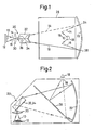
- Figures 1 and 2 of the drawings illustrate a first embodiment of an optical viewing system according to the invention for producing a 3-dimensional effect.
- the system will be contained in a suitable housing (shown is dotted outline in Figure 2)for shielding the system from stray light, and the various components of the sytem will be mounted in the housing by means of suitable supporting structures.
- a suitable housing shown is dotted outline in Figure 2 for shielding the system from stray light
- the various components of the sytem will be mounted in the housing by means of suitable supporting structures.
- suitable housing shown is dotted outline in Figure 2 for shielding the system from stray light
- the various components of the sytem will be mounted in the housing by means of suitable supporting structures.
- An object 10 to be viewed is positioned in a suitable holder 12 provided in the housing in the optical path of the system.
- the holder may be either fixed or movable manually for scanning across larger objects.
- the optical system is arranged to project two separate images the object 10 along separate paths 14, 16 which are prevented from co-mingling in the system,and to reflect these images into an eye opening or exit pupil 18.
- An eye 19 positioned at the exit pupil will receive the images separately on opposite halves of the retina, and the two sets of information will be registered by the brain and interpreted as a 3-dimensional picture, as discussed in more detail below.
- the optical system basically comprises an image projecting assembly 20 for projecting two separate images of the object 10 from slightly different angles along the separate paths 14 and 16, and a concave reflecting mirror 22 on which the separate images are focussed at separate locations 24 and 26.
- the images are reflected from the concave mirror onto a beamsplitter 28 which reflects them into the exit pupil 18.
- the image projecting assembly 20 comprises a lens 30 mounted above the object, and a pair of contiguous planar mirrors 32, 34 meeting along a single edge 36 to form a corner mirror.
- the mirrors 32 and 34 are arranged to reflect two separate images of the object along the paths 14 and 16 from opposite halves of the lens 30.
- the mirrors are positioned so that they do not coincide with a focal plane of the lens and so that their dividing line 36 splits the image from the lens.
- Each mirror acts as a shutter for one half of the lens.
- one mirror 32 is directed at one half of the lens so as to project the image from that half of the lens only, and the other mirror 34 is directed at the opposite half of the lens so as to project the image from that half only.
- the mirrors 32 and 34 meet at a 90 degree angle.
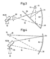
- the elements of the image projecting assembly are extended in a flattened out position to facilitate the illustration of the individual optical paths. The lens and object would actually be below the pair of mirrors.
- the mirrors 32, 34 in both Figure 2 and Figure 3 are preferably positioned as close to the lens as possible to give the best possible separation of the two images.
- the separate images then pass through the beamsplitter 28 and are focused at the separate locations 24, 26 on the surface of the concave mirror 22.
- the concave mirror is preferably substantially spherical.
- the images are reflected from the concave mirror 22 onto the beamsplitter 28, which reflects both images separately into the exit pupil 18 for viewing by a single eye.
- the exit pupil 18 is located at a radius of the spherical mirror 22, as seen in Figure 2, so that the images received at the exit pupil and eye 19 are in focus. Since two different views of the object from slightly different angles are simultaneously and separately directed into the exit pupil 18 and viewer's eye 19, the eye will "see " a 3-dimensional effect.
- optical system described above allows a 3-dimensional effect to be seen with one eye only, eliminating focussing and alignment problems with two eye viewing.
- the exit pupil in Figures 1 and 2 may be very small and need not be larger than the eye pupil, since no head or eye movement is neces sary to "see " the 3-dimensional effect or depth of the object. In fact at very high magnifications (125X) the exit pupil may be smaller than the eye pupil while still allowing the 3-D effect to be seen.
- a pair of exit pupils 18A and 18B are used, one for each eye, instead of the single exit opening shown in the drawings.
- the separate images are kept separate in this embodiment and directed to the right and left eye exit pupils 18A, 18B, respectively, so that the two separate imagesare combined by the viewer into a 3-D picture.
- the embodiment of the invention in which two exit pupils are used is useful for those individuals who find it awkward to view objects using one eye only and prefer to use both eyes.
- one image is received by the retina of the left eye and the other image is received by the retina of the right eye.
- the two images are registered by the brain as a 3-D picture.
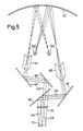
- FIG 5 separate images viewed from the left and from the right of the object 10 are projected by lens 30 through a beamsplitter 40 along the separated paths 44, 42.
- the lefthand image 44 is reflected via an inclined mirror 46 and corner mirror 48 through a further beamsplitter onto concave spherical mirror 22, and then reflected through the exit pupil 18B into the left eye of an observer.
- the righthand image 42 is reflected via inclined mirrors 50, 52 and corner mirror 54 through a beamsplitter onto the spherical mirror, and then directed out via right exit pupil 18A into the right eye of the observer.
- the ninety-degree corner mirrors 48 and 54 are at 45° to the optical path to invert and revert the separate images.
- the system of inclined beamspliter 40 and mirrors 46,48, 50, 52 and 54 are arranged to reflect separate views of the object 10 from different sides along separate paths through the entire optical system.
- Mirror 50 is therefore inclined so as to effectively shutter the lefthand side of the lens 30 and only views the image projected through the righthand side of the lens 30, i.e. the view of the object 10 from the right.
- the mirror 46 is inclined to the beamsplitter 40 so as to shutter the righthand side of the reflected lens image and views only the image projected through the left of the lens, i.e. a view of the object from the left.
- the 3-dimensional picture viewed in the optical systems of this invention described above has little or no tendency to flatten out at high magnifications and will have no "color fringing" effects, with distinct “clean " edges on objects viewed through the system. It will be possible to "see around" objects in the field of view by moving the eye position in the exit pupil.
- the optical viewing system of this invention has improved resolution, with resolutions of the order of 1 micron at 92X magnification having been achieved. It may be used, for example, for inspecting or viewing objects on which very small scale features, defects or irregularities can occur, such as solder joints on printed circuit boards, hybrid microelectronics assemblies, eye implant lenses, surface mount devices, and so on.
Landscapes
- Physics & Mathematics (AREA)
- General Physics & Mathematics (AREA)
- Optics & Photonics (AREA)
Applications Claiming Priority (2)
| Application Number | Priority Date | Filing Date | Title |
|---|---|---|---|
| JP62244845A JPS6488420A (en) | 1987-09-29 | 1987-09-29 | Stereoscopic image optical device |
| JP244845/87 | 1987-09-29 |
Publications (1)
| Publication Number | Publication Date |
|---|---|
| EP0309630A1 true EP0309630A1 (fr) | 1989-04-05 |
Family
ID=17124829
Family Applications (1)
| Application Number | Title | Priority Date | Filing Date |
|---|---|---|---|
| EP87309463A Withdrawn EP0309630A1 (fr) | 1987-09-29 | 1987-10-27 | Système de contrôle de visée optique 3-dimensionnel |
Country Status (2)
| Country | Link |
|---|---|
| EP (1) | EP0309630A1 (fr) |
| JP (1) | JPS6488420A (fr) |
Cited By (5)
| Publication number | Priority date | Publication date | Assignee | Title |
|---|---|---|---|---|
| GB2284068A (en) * | 1993-11-12 | 1995-05-24 | Sharp Kk | Three-dimensional projection display apparatus |
| US5552934A (en) * | 1994-03-18 | 1996-09-03 | Spm Corporation | Background reflection-reducing plano-beam splitter for use in real image projecting system |
| US5886818A (en) * | 1992-12-03 | 1999-03-23 | Dimensional Media Associates | Multi-image compositing |
| US6318868B1 (en) | 1997-05-01 | 2001-11-20 | Larussa Joseph A. | Interactive virtual image store window |
| WO2006003157A1 (fr) * | 2004-07-01 | 2006-01-12 | Siemens Aktiengesellschaft | Dispositif de visualisation et procede pour faire fonctionner ce dernier |
Families Citing this family (1)
| Publication number | Priority date | Publication date | Assignee | Title |
|---|---|---|---|---|
| US7381064B2 (en) * | 2003-08-26 | 2008-06-03 | Methode Electronics, Inc. | Flexible flat cable termination structure for a clockspring |
Citations (3)
| Publication number | Priority date | Publication date | Assignee | Title |
|---|---|---|---|---|
| DE2058675A1 (de) * | 1970-11-28 | 1972-06-08 | Leitz Ernst Gmbh | Bildumlenksystem fuer Stereomikroskope |
| US4232968A (en) * | 1978-12-26 | 1980-11-11 | Kempf Paul S | Optical comparator with 3-D image |
| EP0140836A2 (fr) * | 1983-11-03 | 1985-05-08 | Projectina AG | Appareil optique pour engendrer une image visuelle stéréoscopique |
Family Cites Families (1)
| Publication number | Priority date | Publication date | Assignee | Title |
|---|---|---|---|---|
| DE3565322D1 (en) * | 1984-06-29 | 1988-11-03 | Wild Heerbrugg Ag | Microscope with a binocular tube |
-
1987
- 1987-09-29 JP JP62244845A patent/JPS6488420A/ja active Pending
- 1987-10-27 EP EP87309463A patent/EP0309630A1/fr not_active Withdrawn
Patent Citations (3)
| Publication number | Priority date | Publication date | Assignee | Title |
|---|---|---|---|---|
| DE2058675A1 (de) * | 1970-11-28 | 1972-06-08 | Leitz Ernst Gmbh | Bildumlenksystem fuer Stereomikroskope |
| US4232968A (en) * | 1978-12-26 | 1980-11-11 | Kempf Paul S | Optical comparator with 3-D image |
| EP0140836A2 (fr) * | 1983-11-03 | 1985-05-08 | Projectina AG | Appareil optique pour engendrer une image visuelle stéréoscopique |
Cited By (6)
| Publication number | Priority date | Publication date | Assignee | Title |
|---|---|---|---|---|
| US5886818A (en) * | 1992-12-03 | 1999-03-23 | Dimensional Media Associates | Multi-image compositing |
| GB2284068A (en) * | 1993-11-12 | 1995-05-24 | Sharp Kk | Three-dimensional projection display apparatus |
| US5703717A (en) * | 1993-11-12 | 1997-12-30 | Sharp Kabushiki Kaisha | Three-dimensional projection display apparatus |
| US5552934A (en) * | 1994-03-18 | 1996-09-03 | Spm Corporation | Background reflection-reducing plano-beam splitter for use in real image projecting system |
| US6318868B1 (en) | 1997-05-01 | 2001-11-20 | Larussa Joseph A. | Interactive virtual image store window |
| WO2006003157A1 (fr) * | 2004-07-01 | 2006-01-12 | Siemens Aktiengesellschaft | Dispositif de visualisation et procede pour faire fonctionner ce dernier |
Also Published As
| Publication number | Publication date |
|---|---|
| JPS6488420A (en) | 1989-04-03 |
Similar Documents
| Publication | Publication Date | Title |
|---|---|---|
| US4840455A (en) | 3-dimensional optical viewing system | |
| US4623223A (en) | Stereo image display using a concave mirror and two contiguous reflecting mirrors | |
| US3818125A (en) | Stereo television microscope | |
| US3712199A (en) | Three-dimensional color photographic process, apparatus and product | |
| US4756601A (en) | Three-dimensional image-viewing apparatus | |
| JP2548524B2 (ja) | 光学拡大装置 | |
| US3959580A (en) | Directly viewable stereoscopic projection system | |
| US5351152A (en) | Direct-view stereoscopic confocal microscope | |
| JPH05504449A (ja) | 自動ステレオスコピックディスプレイ用の単一の像レシーバで像を記録する方法及び装置 | |
| EP0795142A1 (fr) | Ameliorations apportees a l'eclairage et la visualisation stereo d'un microscope | |
| EP0577268B1 (fr) | Système optique | |
| US4704012A (en) | Stereoscopic microscope | |
| US6020993A (en) | 3-D photo attachment for a 2-D light microscope | |
| US4943860A (en) | Three-dimensional photographing and three-dimensional playback device by spatial time-sharing method | |
| EP0309630A1 (fr) | Système de contrôle de visée optique 3-dimensionnel | |
| JPH01118814A (ja) | 凹面鏡と接合鏡を用いた立体画像表示装置、立体画像装置および立体画像作成方法 | |
| US20040169922A1 (en) | Stereo microscopy | |
| EP0310721A1 (fr) | Dispositif de visualisation stéréoscopique utilisant un miroir concave et deux miroirs réflecteurs contigus | |
| JPH0297910A (ja) | 顕微鏡用光学系アタッチメント | |
| JPS62166310A (ja) | 固体撮像素子を用いた実体顕微鏡 | |
| SU1515133A1 (ru) | Устройство дл воспроизведени стереоскопических изображений | |
| JPH05244643A (ja) | 立体テレビ装置 | |
| CN215499362U (zh) | 立体镜头 | |
| JP3735134B2 (ja) | 立体映像表示装置 | |
| JPWO2016035891A1 (ja) | 光学アダプタおよびこれを用いた立体撮像システム |
Legal Events
| Date | Code | Title | Description |
|---|---|---|---|
| PUAI | Public reference made under article 153(3) epc to a published international application that has entered the european phase |
Free format text: ORIGINAL CODE: 0009012 |
|
| 17P | Request for examination filed |
Effective date: 19880920 |
|
| AK | Designated contracting states |
Kind code of ref document: A1 Designated state(s): DE FR GB IT NL |
|
| STAA | Information on the status of an ep patent application or granted ep patent |
Free format text: STATUS: THE APPLICATION IS DEEMED TO BE WITHDRAWN |
|
| 18D | Application deemed to be withdrawn |
Effective date: 19910510 |
|
| RIN1 | Information on inventor provided before grant (corrected) |
Inventor name: YAMAZAKI, ARATA |