EP0309633B1 - Alarmsystem mit pneumatischer Steuerung für ein pneumatisches Beatmungsgerät - Google Patents
Alarmsystem mit pneumatischer Steuerung für ein pneumatisches Beatmungsgerät Download PDFInfo
- Publication number
- EP0309633B1 EP0309633B1 EP87420261A EP87420261A EP0309633B1 EP 0309633 B1 EP0309633 B1 EP 0309633B1 EP 87420261 A EP87420261 A EP 87420261A EP 87420261 A EP87420261 A EP 87420261A EP 0309633 B1 EP0309633 B1 EP 0309633B1
- Authority
- EP
- European Patent Office
- Prior art keywords
- valve
- reservoir
- gas
- audible alarm
- alarm system
- Prior art date
- Legal status (The legal status is an assumption and is not a legal conclusion. Google has not performed a legal analysis and makes no representation as to the accuracy of the status listed.)
- Expired - Lifetime
Links
- 230000000007 visual effect Effects 0.000 claims description 7
- 239000012528 membrane Substances 0.000 claims description 5
- 230000005764 inhibitory process Effects 0.000 claims description 4
- 230000001960 triggered effect Effects 0.000 abstract description 2
- 239000007789 gas Substances 0.000 description 26
- 238000009434 installation Methods 0.000 description 9
- 240000008042 Zea mays Species 0.000 description 3
- 230000005236 sound signal Effects 0.000 description 3
- GQPLMRYTRLFLPF-UHFFFAOYSA-N Nitrous Oxide Chemical compound [O-][N+]#N GQPLMRYTRLFLPF-UHFFFAOYSA-N 0.000 description 2
- QVGXLLKOCUKJST-UHFFFAOYSA-N atomic oxygen Chemical compound [O] QVGXLLKOCUKJST-UHFFFAOYSA-N 0.000 description 2
- 239000000203 mixture Substances 0.000 description 2
- 239000001301 oxygen Substances 0.000 description 2
- 229910052760 oxygen Inorganic materials 0.000 description 2
- 238000010926 purge Methods 0.000 description 2
- 230000000241 respiratory effect Effects 0.000 description 2
- 238000011144 upstream manufacturing Methods 0.000 description 2
- 238000010586 diagram Methods 0.000 description 1
- 230000000694 effects Effects 0.000 description 1
- 239000001272 nitrous oxide Substances 0.000 description 1
- 230000007420 reactivation Effects 0.000 description 1
- 230000029058 respiratory gaseous exchange Effects 0.000 description 1
- 238000013022 venting Methods 0.000 description 1
Images

Classifications
-
- A—HUMAN NECESSITIES
- A61—MEDICAL OR VETERINARY SCIENCE; HYGIENE
- A61M—DEVICES FOR INTRODUCING MEDIA INTO, OR ONTO, THE BODY; DEVICES FOR TRANSDUCING BODY MEDIA OR FOR TAKING MEDIA FROM THE BODY; DEVICES FOR PRODUCING OR ENDING SLEEP OR STUPOR
- A61M16/00—Devices for influencing the respiratory system of patients by gas treatment, e.g. ventilators; Tracheal tubes
- A61M16/0051—Devices for influencing the respiratory system of patients by gas treatment, e.g. ventilators; Tracheal tubes with alarm devices
Definitions
- Alarm systems can be divided into two types: electrical or electronic, and pneumatic.
- Electric or electronic alarm systems do not have any major drawbacks when it comes to respirators associated with fixed installations, which is the case in operating theaters.
- these systems require electrical energy supplied by batteries or accumulators.
- the batteries or accumulators are not always in working order; and in addition, such sources of electrical energy cannot be used in certain atmospheres, for example in an explosion-proof atmosphere.
- French Patent No. 2,203,481 and British No. 817,289 disclose pneumatic alarm systems, very different from the subject of claim 1 as said gas comprise two circuits one of which is primary and the other secondary and that the operation of the alarm requires the use of two gases, the gas of the secondary circuit (nitrous oxide) causing the triggering of the alarm depending on the pressure prevailing in the circuit.
- the invention aims to remedy these drawbacks by proposing a fully pneumatic control alarm system which, associated with a pneumatic respirator, can be used on any fixed or mobile installation, is very simple and requires only one very low gas consumption.
- a bypass comprising a valve of the snap-open type which is held in the open position by a spring and which, in its open position, supplies gas an audible pneumatic alarm system, this valve being subjected to a piloting signal to control, as a function of the pressure prevailing in the circuit connecting the pneumatic respirator to the patient, either upon closing of this valve and stopping the audible alarm, on the contrary, the opening of this valve and the operation of the alarm.
- the audible alarm system consists of a reservoir which is connected to the outlet port of the valve and is divided by a membrane into two chambers connected to the source of gas coming from the valve, one by a pipe containing a fixed resistance, and the other by a pipe containing a variable resistance, the latter chamber comprising an orifice for venting to the open air. It is the vibration of this membrane which constitutes the sound signal; its intensity is adjustable by acting on the variable resistance provided on the pipe supplying the chamber communicating with the open air.
- an amplifier relay connected to the circuit connecting the ventilator to the patient, and supplied by a source of pressurized gas, and this relay is connected, with the interposition of a non-return valve, to a reservoir which is connected to the valve controlling the audible alarm and whose gas under pressure constitutes the means for controlling the closing of this valve which has two other orifices for its connection respectively to a source of pressurized gas and to the sound signal.
- this pneumatically controlled alarm system to be effective in all conditions of use, it is supplemented by a visual signal consisting of an indicator pneumatic with logic "inhibition" function which is connected on the one hand, to the gas tank controlling the closing of the valve controlling the operation of the audible alarm, and on the other hand to the circuit connecting the patient to the ventilator.
- 1 designates the source of pressurized gas supply; it can be a portable bottle or the network of a fixed installation.
- 2 designates a valve whose normal position is that of opening; this type of valve is generally designated by the acronym "NO”.
- 3 generally designates an audible alarm.
- the valve 2 subjected to the action of a spring 4 tending to keep it in the open position is slaved to a piloting signal whose operation is controlled for example by the pressure prevailing in the connecting circuit the patient on the respirator or by the pressure of the breathing gas in the safety mixer usually used.
- This valve 2 is connected to the gas supply source 1 by a pipe 5 comprising from upstream to downstream a non-return valve 6 and a small tank 7.
- the valve 2 is connected not only to this tank 7, but also to the audible alarm 3 by a pipe 8 having two branches respectively 9 and 10 ending in the body of the alarm which is divided into two chambers 12 and 13 by a membrane 11.
- In the chamber 12 opens the pipe 9 which contains a fixed resistance 14.
- In the chamber 13 opens the pipe 10 which contains a variable resistance 15; and this chamber 13 comprises a vent tube 16.
- the valve 2 When the system is in the rest position, the valve 2 occupies the open position shown in FIG. 1. In this position, the alarm 3 is supplied through the valve 2 by the reservoir 7 connected to the source 1 d gas supply. The gas entering the body of the alarm through the lines 9 and 10 causes vibration of the membrane 11; and the sound level of this vibration is adjustable by manual action on the resistor 15.
- the reservoir 7 may or may not be supplied by the same source of gas as the respirator connected to the patient. If the power supply is the same, the system can be completely autonomous.
- the operating time of the audible signal 3 is of the order of 7 to 10 seconds in the event of a complete cut off of the supply to the reservoir 7 of gas, but that if the pressure drop is gradual, the signal run time is much longer.
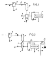
- FIGS 3 and 4 show a system of the same kind, but in which the valve 2 (NO valve) is controlled by an amplifier relay 17 controlled at very low pressure.
- the control signal comes from the connection of the relay 17 by a pipe 18 on the circuit connecting the patient to the ventilator; and the amplifier relay 17 is also connected directly to the gas supply source 19, the supply pressure generally being between 1 and 10 bars.
- valve 2 normally maintained in the open position by its return spring 4 is connected, on the one hand, directly by a pipe 21 to a gas supply source 22 which may be identical or different from the source 19.
- the valve 2 is also connected, as in the previous case, to the audible alarm 3.
- each insuflation causes an increase in the pressure and thus controls the amplifier relay 17 which delivers an amplified signal whose pressure is for example 1.5 bar.
- This signal causes the valve 2 to close and thus suppresses the operation of the alarm sound signal, because the amplifier relay 17 is connected to the valve 2 by a pipe 23 comprising a non-return valve 24, and by a connected tank 25 on valve 2.
- the amplifier relay 17 is released, and the reservoir 25 is purged very slowly by an inverse flow rate of the non-return valve 24 which in fact opposes a very high resistance.
- the system is reactivated; and it takes more than ten seconds without reactivation for the valve 2 to open suddenly under the effect of its return spring 4, causing the operation of the audible alarm. This is particularly the case if the circuit connecting the patient to the ventilator no longer registers a rise in pressure; this is particularly the case if the patient disconnects.
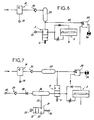
- FIG. 5 and 6 The system shown in Figures 5 and 6 is identical to that of Figures 3 and 4, but is improved in that the audible alarm 3 is associated with a visual alarm.
- This alarm is constituted by a pneumatic indicator 26 with logic "inhibition" function 27, connected on the one hand by a pipe 28 to or at the outlet of the tank 25, and connected on the other hand by a pipe 29 on the control of inspiration.
- the indicator 26 When the pressure in the reservoir 25 is sufficiently high, the indicator 26 is inhibited. On the other hand, when the pressure drops, the inhibition disappears, and the indicator 26 is then actuated at the same rate as the ventilator. This is the case, for example, when the patient is disconnected.
- the system shown in Figure 7 differs from that illustrated in Figures 5 and 6 only by the addition of an additional member.
- It is a command button 31 which allows at will to deactivate the audible alarm 3.
- This member 31 is constituted by a valve 32 which is connected by a pipe 33 to a reservoir 34 and which has a purge orifice 35.
- This valve 32 is subjected to the action of a tensioning spring 36 to keep it in the closed position; and it includes a push button 37 allowing manual opening.
- the reservoir 34 is interposed between the valve 2 (NO valve) and the gas supply source 22; and upstream of the reservoir 34, a resistance 38 and a non-return valve 39 are provided.
- the valve 32 In the normal position, the valve 32 is closed; the audible alarm 3 and the indicator light 26 therefore operate as in the previous case (FIGS. 5 and 6), the supply of the audible alarm 3 being made through the valve 2 by the reservoir 34.
- the audible alarm 3 and the indicator 26 thus operate normally in the event of disconnection of the patient or in the event of a pressure drop; but an action on the push-button 37 makes it possible to immediately purge the tank 34.
- the audible alarm 3 therefore stops working; but the visual alarm 26 continues to operate. It suffices to release the push button 37 so that the reservoir 34 fills again through the resistance 38 which is weaker than that of the audible alarm 3 and so that after a few moments, the audible alarm 3 works again.
Landscapes
- Health & Medical Sciences (AREA)
- Emergency Medicine (AREA)
- Pulmonology (AREA)
- Engineering & Computer Science (AREA)
- Anesthesiology (AREA)
- Biomedical Technology (AREA)
- Heart & Thoracic Surgery (AREA)
- Hematology (AREA)
- Life Sciences & Earth Sciences (AREA)
- Animal Behavior & Ethology (AREA)
- General Health & Medical Sciences (AREA)
- Public Health (AREA)
- Veterinary Medicine (AREA)
- Respiratory Apparatuses And Protective Means (AREA)
Claims (5)
- Alarmsystem mit pneumatischer Steuerung für ein pneumatisches Beatmungsgerät, dadurch gekennzeichnet, daß von dem Kreislauf (1, 22) der das Beatmungsgerät mit dem Patienten verbindet, eine Zweigleitung abgezweigt ist, die ein Schnellschaltventil (2) welches mit Hilfe einer Feder (4) in Durchlaßstellung gehalten wird und welches ein pneumatisch funktionierendes akustisches Alarmsystem (3) mit Gas versorgt, beinhaltet, wobei das Ventil (2) durch ein Steuersignal x beaufschlagt wird, um abhängig von dem Druck, der in dem Kreislauf zwischen Beatmungsgerät und Patient herrscht, sei es das Schließen des Ventils (2) und das Unterbrechen des akustischen Alarms (3), sei es im Gegenteil das Öffnen des Ventils (2) und das Ingangsetzen des Alarms (3) zu steuern, wobei ein durch ein Rückschlagventil (6) gefüllter Gasspeicher (7) vorgesehen ist, der das Ventil (2) mit der Versorgungsquelle (1) verbindet und der die Funktion des akustischen Alarms bei Öffnen des Ventils (2) sicherstellt.
- Alarmsystem mit pneumatischer Steuerung nach Anspruch 1, dadurch gekennzeichnet, daß sein akustisches Alarmsystem einen Speicher beinhaltet, der mit der Ausgangsöffnung des Ventiles (2) verbunden ist und der durch eine Membrane (11) in zwei Kammern (12, 13) geteilt wird, die unter Zwischenschaltung des Ventiles (2) mit der Gasquelle verbunden sind, wobei sich in der Leitung zwischen Ventil (2) und Kammer (12) ein fester Widerstand befindet, wohingegen sich in der Zuleitung zur Kammer (13), die eine Öffnung zur Umgebungsluft hat, ein regelbarer Widerstand (15) befindet.
- Alarmsystem mit pneumatischer Steuerung nach den Ansprüchen 1 und 2, dadurch gekennzeichnet, daß mit dem Kreislauf zwischen Patient und Beatmungsgerät ein Verstärkungsrelais (17) verbunden ist, das von einer Druckgasquelle versorgt wird und der unter Zwischenschaltung eines Rückschlagventils (24) an einen Speicher (25) angeschlossen ist, der wiederum mit dem Ventil (2), welches den akustischen Alarm steuert, verbunden ist, wobei folglich dessen Gas das Steuermittel zum Schließen des Ventils bildet, das zwei weitere Anschlußöffnungen für eine Druckgasquelle und für das akustische Alarmsignal besitzt.
- Alarmsystem mit pneumatischer Steuerung nach einem der Ansprüche 1 bis 3, dadurch gekennzeichnet, daß sie durch ein optisches Signal vervollständigt wird, das durch eine pneumatische Anzeigeeinrichtung (26) mit logischer Inhibitionsfunktion, die auf der einen Seite mit dem Gasspeicher (25), der das Schließen des Ventiles (2) veranlaßt, welches die Funktion des akustischen Alarms (3) steuert, und auf der anderen Seite mit dem Kreislauf zwischen Beatmungsgerät und Patient verbunden ist.
- Alarmsystem mit pneumatischer Steuerung nach einem der Ansprüche 1 bis 4, dadurch gekennzeichnet, daß der akustische Alarm (3) über das Ventil (2) von einem Speicher (34) versorgt wird, der unter Zwischenschaltung eines Widerstandes (38) und eines Rückschlagventils (39) mit einer Druckgasquelle verbunden ist, wobei der Speicher (34) mit einem zweiten Ventil (31) in Verbindung steht, welches eine Öffnung zur Umgebungsluft besitzt und mit Hilfe einer Feder (36) in Schließstellung gehalten wird und welches einen Druckknopf trägt, der es ermöglicht, das Ventil zu öffnen, um dem Speicher (34) mit der Umgebungsluft zu verbinden.
Priority Applications (4)
| Application Number | Priority Date | Filing Date | Title |
|---|---|---|---|
| FR8610932A FR2601877B1 (fr) | 1986-07-24 | 1986-07-24 | Systeme d'alarme a commande pneumatique pour respirateur pneumatique |
| AT87420261T ATE74284T1 (de) | 1987-09-30 | 1987-09-30 | Alarmsystem mit pneumatischer steuerung fuer ein pneumatisches beatmungsgeraet. |
| DE8787420261T DE3778021D1 (de) | 1987-09-30 | 1987-09-30 | Alarmsystem mit pneumatischer steuerung fuer ein pneumatisches beatmungsgeraet. |
| EP87420261A EP0309633B1 (de) | 1987-09-30 | 1987-09-30 | Alarmsystem mit pneumatischer Steuerung für ein pneumatisches Beatmungsgerät |
Applications Claiming Priority (1)
| Application Number | Priority Date | Filing Date | Title |
|---|---|---|---|
| EP87420261A EP0309633B1 (de) | 1987-09-30 | 1987-09-30 | Alarmsystem mit pneumatischer Steuerung für ein pneumatisches Beatmungsgerät |
Publications (2)
| Publication Number | Publication Date |
|---|---|
| EP0309633A1 EP0309633A1 (de) | 1989-04-05 |
| EP0309633B1 true EP0309633B1 (de) | 1992-04-01 |
Family
ID=8198294
Family Applications (1)
| Application Number | Title | Priority Date | Filing Date |
|---|---|---|---|
| EP87420261A Expired - Lifetime EP0309633B1 (de) | 1986-07-24 | 1987-09-30 | Alarmsystem mit pneumatischer Steuerung für ein pneumatisches Beatmungsgerät |
Country Status (3)
| Country | Link |
|---|---|
| EP (1) | EP0309633B1 (de) |
| AT (1) | ATE74284T1 (de) |
| DE (1) | DE3778021D1 (de) |
Families Citing this family (3)
| Publication number | Priority date | Publication date | Assignee | Title |
|---|---|---|---|---|
| US5632270A (en) * | 1994-09-12 | 1997-05-27 | Puritan-Bennett Corporation | Method and apparatus for control of lung ventilator exhalation circuit |
| US9999546B2 (en) | 2014-06-16 | 2018-06-19 | Illinois Tool Works Inc. | Protective headwear with airflow |
| US11812816B2 (en) | 2017-05-11 | 2023-11-14 | Illinois Tool Works Inc. | Protective headwear with airflow |
Family Cites Families (4)
| Publication number | Priority date | Publication date | Assignee | Title |
|---|---|---|---|---|
| GB817289A (en) * | 1956-04-17 | 1959-07-29 | British Oxygen Co Ltd | Fluid pressure warning device |
| GB1073704A (en) * | 1964-07-20 | 1967-06-28 | Westinghouse Brake & Signal | Fluid operable sound producing apparatus |
| FR2203481A5 (de) * | 1972-10-16 | 1974-05-10 | Minerve Sa | |
| US4155357A (en) * | 1976-12-10 | 1979-05-22 | Sandoz, Inc. | Patient ventilator disconnect alarm |
-
1987
- 1987-09-30 EP EP87420261A patent/EP0309633B1/de not_active Expired - Lifetime
- 1987-09-30 DE DE8787420261T patent/DE3778021D1/de not_active Expired - Fee Related
- 1987-09-30 AT AT87420261T patent/ATE74284T1/de not_active IP Right Cessation
Also Published As
| Publication number | Publication date |
|---|---|
| ATE74284T1 (de) | 1992-04-15 |
| EP0309633A1 (de) | 1989-04-05 |
| DE3778021D1 (de) | 1992-05-07 |
Similar Documents
| Publication | Publication Date | Title |
|---|---|---|
| US8307906B2 (en) | Apparatus and method for automatic conversion of sprinkler system | |
| CA2338178C (fr) | Regulateur a la demande pour systeme respiratoire | |
| EP0289386B1 (de) | Hydraulisches Dreiweg-Ventil | |
| EP0287461B1 (de) | Bedarfsabhängiger Regler für Atemgas | |
| EP0309633B1 (de) | Alarmsystem mit pneumatischer Steuerung für ein pneumatisches Beatmungsgerät | |
| FR2601877A1 (fr) | Systeme d'alarme a commande pneumatique pour respirateur pneumatique | |
| FR3002150A1 (fr) | Sprinkler comprenant un opercule d'obturation maintenu en position par un fusible a l'aide d'un moyen d'appui deplacable | |
| EP2300104A1 (de) | Sprühkopf | |
| EP0701841B1 (de) | Feuerschutzeinrichtung | |
| EP2958641B1 (de) | Brandbekämpfungsanlage mit einem netz aus vakuumsprinklern, auslösbar durch einen mittels eines membran-master-aktuators betriebenen aktuator | |
| CA1104907A (fr) | Dispositif de securite pour circuit de commande oleopneumatique | |
| FR2725776A1 (fr) | Generateur de gaz comprime utilise notamment pour l'extinction d'incendie | |
| EP3609753B1 (de) | Vereinfachtes führerbremsventil und pneumatischer bremskreis eines schienenfahrzeugs mit einem solchen führerbremsventil | |
| WO2025068664A1 (fr) | Dispositif d'actionnement securise d'un recipient d'approvisionnement en gaz sous pression dans un aeronef | |
| FR2469183A1 (fr) | Regulateur a la demande pour installation respiratoire | |
| FR2472134A2 (fr) | Separateur de gaz pour dispositif de distribution de liquide | |
| EP0869311A1 (de) | Sicherheitsvorrichtung einer Flüssigkeitsabgabeeinrichtung | |
| WO2014128389A2 (fr) | Installation de lutte contre les incendies, incluant un réseau de sprinklers sous vide, et un organe d'isolement intercalé entre une ligne de contrôle et une ligne d'activation d'alarme hydraulique | |
| FR2756390A1 (fr) | Appareil de regulation automatique de pression de gaz | |
| FR3064964A1 (fr) | Robinet de mecanicien simplifie et circuit pneumatique de freinage d’une rame ferroviaire incorporant un tel robinet de mecanicien | |
| FR2761754A1 (fr) | Dispositif de securite pour installation de distribution d'eau | |
| FR2911379A1 (fr) | Systeme de soupape de securite a assistance perfectionnee |
Legal Events
| Date | Code | Title | Description |
|---|---|---|---|
| PUAI | Public reference made under article 153(3) epc to a published international application that has entered the european phase |
Free format text: ORIGINAL CODE: 0009012 |
|
| AK | Designated contracting states |
Kind code of ref document: A1 Designated state(s): AT BE CH DE ES GB GR IT LI LU NL SE |
|
| 17P | Request for examination filed |
Effective date: 19890623 |
|
| 17Q | First examination report despatched |
Effective date: 19901109 |
|
| GRAA | (expected) grant |
Free format text: ORIGINAL CODE: 0009210 |
|
| AK | Designated contracting states |
Kind code of ref document: B1 Designated state(s): AT BE CH DE ES GB GR IT LI LU NL SE |
|
| PG25 | Lapsed in a contracting state [announced via postgrant information from national office to epo] |
Ref country code: IT Free format text: LAPSE BECAUSE OF FAILURE TO SUBMIT A TRANSLATION OF THE DESCRIPTION OR TO PAY THE FEE WITHIN THE PRE;WARNING: LAPSES OF ITALIAN PATENTS WITH EFFECTIVE DATE BEFORE 2007 MAY HAVE OCCURRED AT ANY TIME BEFORE 2007. THE CORRECT EFFECTIVE DATE MAY BE DIFFERENT FROM THE ONE RECORDED.SCRIBED TIME-LIMIT Effective date: 19920401 Ref country code: GR Free format text: LAPSE BECAUSE OF FAILURE TO SUBMIT A TRANSLATION OF THE DESCRIPTION OR TO PAY THE FEE WITHIN THE PRESCRIBED TIME-LIMIT Effective date: 19920401 Ref country code: NL Effective date: 19920401 Ref country code: SE Effective date: 19920401 Ref country code: AT Effective date: 19920401 |
|
| REF | Corresponds to: |
Ref document number: 74284 Country of ref document: AT Date of ref document: 19920415 Kind code of ref document: T |
|
| REF | Corresponds to: |
Ref document number: 3778021 Country of ref document: DE Date of ref document: 19920507 |
|
| GBT | Gb: translation of ep patent filed (gb section 77(6)(a)/1977) | ||
| PG25 | Lapsed in a contracting state [announced via postgrant information from national office to epo] |
Ref country code: ES Free format text: LAPSE BECAUSE OF FAILURE TO SUBMIT A TRANSLATION OF THE DESCRIPTION OR TO PAY THE FEE WITHIN THE PRESCRIBED TIME-LIMIT Effective date: 19920712 |
|
| NLV1 | Nl: lapsed or annulled due to failure to fulfill the requirements of art. 29p and 29m of the patents act | ||
| PGFP | Annual fee paid to national office [announced via postgrant information from national office to epo] |
Ref country code: GB Payment date: 19920929 Year of fee payment: 6 |
|
| PG25 | Lapsed in a contracting state [announced via postgrant information from national office to epo] |
Ref country code: CH Effective date: 19920930 Ref country code: BE Effective date: 19920930 Ref country code: LU Free format text: LAPSE BECAUSE OF NON-PAYMENT OF DUE FEES Effective date: 19920930 Ref country code: LI Effective date: 19920930 |
|
| PGFP | Annual fee paid to national office [announced via postgrant information from national office to epo] |
Ref country code: DE Payment date: 19921008 Year of fee payment: 6 |
|
| PLBE | No opposition filed within time limit |
Free format text: ORIGINAL CODE: 0009261 |
|
| STAA | Information on the status of an ep patent application or granted ep patent |
Free format text: STATUS: NO OPPOSITION FILED WITHIN TIME LIMIT |
|
| 26N | No opposition filed | ||
| BERE | Be: lapsed |
Owner name: DRAGER Effective date: 19920930 |
|
| REG | Reference to a national code |
Ref country code: CH Ref legal event code: PL |
|
| PG25 | Lapsed in a contracting state [announced via postgrant information from national office to epo] |
Ref country code: GB Effective date: 19930930 |
|
| GBPC | Gb: european patent ceased through non-payment of renewal fee |
Effective date: 19930930 |
|
| PG25 | Lapsed in a contracting state [announced via postgrant information from national office to epo] |
Ref country code: DE Effective date: 19940601 |