EP0309655B1 - Appareil et procédé de traitement d'images - Google Patents
Appareil et procédé de traitement d'images Download PDFInfo
- Publication number
- EP0309655B1 EP0309655B1 EP88110385A EP88110385A EP0309655B1 EP 0309655 B1 EP0309655 B1 EP 0309655B1 EP 88110385 A EP88110385 A EP 88110385A EP 88110385 A EP88110385 A EP 88110385A EP 0309655 B1 EP0309655 B1 EP 0309655B1
- Authority
- EP
- European Patent Office
- Prior art keywords
- image data
- endpoint
- black
- run length
- lines
- Prior art date
- Legal status (The legal status is an assumption and is not a legal conclusion. Google has not performed a legal analysis and makes no representation as to the accuracy of the status listed.)
- Expired - Lifetime
Links
Images



Classifications
-
- H—ELECTRICITY
- H04—ELECTRIC COMMUNICATION TECHNIQUE
- H04N—PICTORIAL COMMUNICATION, e.g. TELEVISION
- H04N1/00—Scanning, transmission or reproduction of documents or the like, e.g. facsimile transmission; Details thereof
- H04N1/41—Bandwidth or redundancy reduction
- H04N1/411—Bandwidth or redundancy reduction for the transmission or storage or reproduction of two-tone pictures, e.g. black and white pictures
-
- H—ELECTRICITY
- H04—ELECTRIC COMMUNICATION TECHNIQUE
- H04N—PICTORIAL COMMUNICATION, e.g. TELEVISION
- H04N1/00—Scanning, transmission or reproduction of documents or the like, e.g. facsimile transmission; Details thereof
- H04N1/41—Bandwidth or redundancy reduction
- H04N1/411—Bandwidth or redundancy reduction for the transmission or storage or reproduction of two-tone pictures, e.g. black and white pictures
- H04N1/413—Systems or arrangements allowing the picture to be reproduced without loss or modification of picture-information
- H04N1/419—Systems or arrangements allowing the picture to be reproduced without loss or modification of picture-information in which encoding of the length of a succession of picture-elements of the same value along a scanning line is the only encoding step
-
- G—PHYSICS
- G06—COMPUTING OR CALCULATING; COUNTING
- G06T—IMAGE DATA PROCESSING OR GENERATION, IN GENERAL
- G06T9/00—Image coding
- G06T9/005—Statistical coding, e.g. Huffman, run length coding
Definitions
- the present invention relates to an image processing apparatus as described in the preamble part of claim 1.
- the present invention relates to an image processing method as described in the preamble part of claim 10.
- a run length coding method is widely used in various image processing apparatuses such as facsimiles to compress image data.
- an original image is subjected to a raster scanning operation to obtain binary image data.
- the binary image data are used to make a bit map, each line of the bit map comprising black dots and white dots.
- the length (run length) of a series of consecutive black dots hereinafter referred to as a "black run”
- the length of a series of consecutive white dots hereinafter referred to as a "white run” as well as positional information of endpoints of the black and white runs are coded with run length codes.
- each run length code comprises, for instance, eight bits.
- a first bit of the eight-bit code is a flag for indicating whether a run is white (0) or black (1), and the remaining bits of the code indicating the length of the run. Supposing a data comprises two consecutive white dots, three consecutive black dots and two consecutive white dots, the data will be coded as "02, 83, 02" in hexadecimal notation.
- horizontal and vertical run length data are frequently used to extract linear elements from an input image or to remove noises from the input image.
- horizontal and vertical black runs are used as information to find horizontal and vertical projections.
- the run length coding is generally carried out for the same direction as that of raster scan which takes place, for instance in a horizontal direction. Therefore, to obtain information of vertical components, coded horizontal run data shall be decoded into an original bit map (binary image data), and based on which vertical run length codes shall be prepared to obtain vertical projections, etc. Due to this, an image memory needed for the method shall have a large capacity. Further, the process to obtain vertical components shall be carried out for every pixel so that the number of memory accesses and the number of computation may be increased to extend an operation time.
- the conventional image processing apparatus requires a large memory capacity and takes a long time in carrying out an image process such as the horizontal-to-vertical converting operation to obtain run length codes for a direction different from a scanning direction.
- An object of the present invention is to provide an image processing apparatus and an image processing method as described hereinabove which can obtain run length codes from a direction different from a scanning direction at a high speed and with a small memory capacity.
- an image processing apparatus which encodes an original image with run length codes for a first direction to obtain input image data and carries out an exclusive OR operation on the data of adjacent two lines of the input image data to detect endpoints for a second direction which is different from the first direction.
- the apparatus comprises an input image memory for storing the input image data obtained by coding the original image data with the run length codes for the first direction, a reading circuit for sequentially reading from the input image memory the inputted image data of the two lines which are adjacent to each other in the second direction orthogonal to the first direction, an exclusive OR processing circuit for carrying out an exclusive OR operation on the input image data of the adjacent two lines sequentially read by the reading device without decoding the data into the original image data to detect endpoint positions for the second direction of the original image data, and a second directional processing circuit for carrying out a predetermined image process for the second direction according to the endpoint positions for the second direction detected by the exclusive OR processing circuit.
- the data of adjacent two lines of the input image data are subjected to the exclusive OR operation to extract positions where the run length codes are different from each other to detect endpoint positions for the second direction. Once the endpoint positions for the second direction are detected, an image process for the second direction may be easily performed.
- the input image data coded with run length codes are not decoded into the original image data but processed as they are to detect the endpoint positions for the second direction, thereby realizing a high-speed process with a small memory capacity.
- Figs. 1 to 7 are views for explaining a horizontal-to-vertical conversion processing apparatus according to an embodiment of the present invention.
- the apparatus is for converting horizontal runs (runs in a first direction) into vertical runs (runs in a second direction).
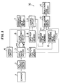
- Fig. 1 is a block diagram showing the constitution of the apparatus.
- a scanner 1 carries out a raster scanning operation on an original image to output binary image data as original image data.
- a run length coding circuit 2 sequentially encodes the binary image data with run length codes to provide horizontal run length data which are outputted as input image data to an input image memory 3.
- the input image memory 3 stores the input image data transferred from the run length coding circuit 2.
- a first-line flag memory 4 is a register for storing flags only in the first line data among the input image data stored in the input image memory 3.
- a control circuit 5 specifies a read address with respect to the input image memory 3 to read the data of adjacent two lines, i.e., a line "j-1" and a line "j" from the input image memory 3.
- the data of the lines j-1 and j sequentially read out of the input image memory 3 under the control of the control circuit 5 are given to an exclusive logical add processing circuit (hereinafter referred to as the "EX-OR processing circuit") 6.
- the EX-OR processing circuit 6 carries out an exclusive OR operation on the data of the lines j-1 and j to detect endpoint coordinate values for a vertical direction.
- An endpoint coordinate value memory 7 stores the endpoint coordinate values detected in the EX-OR processing circuit 6.
- a first-run flag memory 8 is a register for storing flags of first runs of respective lines detected in the EX-OR processing circuit 6.
- a control circuit 9 properly reads data of the endpoint coordinate value memory 7 and of the first-run flag memory 8 to provide the read data to a vertical run conversion processing circuit 10 which is the second directional processing means, and gives a read timing to the control circuit 5 to read the input image memory 3.
- the vertical run conversion processing circuit 10 comprises an endpoint count memory 11, an endpoint coordinate value memory 12, a run length coding circuit 13 and a run length code memory 14.
- the endpoint count memory 11 stores the numbers of endpoints for a vertical direction in each column of the input image data.
- the endpoint coordinate value memory 12 is a memory for storing coordinate values of the vertical endpoints of each column.
- the run length coding circuit 13 receives the numbers of endpoints of the respective columns from the endpoint count memory 11, the endpoint coordinate values of the respective columns from the endpoint coordinate value memory 12 and the flags of respective runs in the first line from the first-line flag memory 4 to carry out the vertical run length coding operation.
- the run length code memory 14 is a memory for storing the vertical run length codes prepared in the run length coding circuit 13.
- Original image data read by the scanner 1 are encoded with run length codes for the horizontal direction in the run length coding circuit 2.
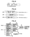
- Each run length code comprises, for instance, one byte (eight bits) as shown in Fig. 2.
- a first bit of the code is a flag for identifying that a run is white (0) or black (1).
- the following 7 bits indicate the length of the run.
- lines j-1, j and j+1 of the original image data shown in Fig. 3 are coded with run length codes as indicated with hexadecimal numerals in the right side of the figure. These run length codes are stored for each line in the input image memory 3.
- the input image data for adjacent two lines are sequentially read and transferred to the EX-OR processing circuit 6 for an endpoint detection process.
- Fig. 4 is a view showing an example of the constitution of the EX-OR processing circuit 6.
- the run length codes for the lines j-1 and j are given to endpoint coordinate value detecting circuits 21 and 22 respectively to find endpoint coordinate values for the horizontal direction.
- the horizontal endpoint coordinate values of the respective lines thus found are stored in endpoint coordinate value memories 23 and 24.
- the endpoint coordinate values stored in the memories 23 and 24 are given to and sorted in a sorting circuit 25.
- the sorting circuit 25 abandons the values and, when the memories 23 and 24 provide different values, the circuit 25 sorts the values.
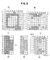
- Fig. 5 shows various processing states of image data.
- input image data 32 represented with run length codes for the horizontal direction.
- the run length codes are converted into horizontal coordinate values (i) to obtain data 33.
- Only different values in adjacent two lines among the data 33 are arranged in an ascending order, and a line head number "1" is added to the head of the arranged line while a line tail number plus one, i.e., "11" is added to the tail of the arranged line to obtain output data 34.
- the output data 34 are stored in the endpoint coordinate value memory 7.
- the output data 34 may correspond to image data 35 shown in Fig. 5. Comparing the image data 35 with the original image data 31, it will be seen that the image data 35 have bits at changing points where dots change from white to black or from black to white. Namely, the image data 35 indicate endpoint positions for the vertical direction.
- a first-run flag EX-OR circuit 26 shown in Fig. 4 extracts first-run flags of the lines j-1 and j to carry out the exclusive OR operation on the extracted flags and output the results to the first-run flag memory 8.
- the endpoint count memory 11 is a one-dimensional memory corresponding to one line of the original image data.
- the contents of the memory 11 are represented with N(i).
- the endpoint coordinate value memory 12 is a two-dimensional memory having a capacity of storing vertical endpoints for every line of the original image data.
- the contents of the memory 12 are represented with J(i, k).
- the endpoint coordinate value memory 7 shown in Fig. 1 is a one-dimensional memory of which contents are represented with K(l , k) where "k" indicates a current processing point.
- the run length coding circuit 13 refers to the first flag data stored in the first-line flag memory 4 and the endpoint coordinate value data in the endpoint coordinate value memory 12 to provide vertical run length codes. As a result, vertical run length codes as shown in Fig. 7 are obtained and stored in the run length code memory 14.
- the coordinate values of all lines may be stored in the endpoint coordinate value memory 7 before starting the vertical run converting process. Further, it is possible to perform the vertical run length coding operation for every registering operation into the endpoint coordinate value memory 12.
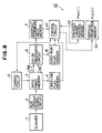
- Figs. 8 to 10 are views showing a vertical projection detector according to another embodiment of the present invention.
- a vertical projection detecting circuit 42 which is used as the second directional processing means comprises a previous change position memory 43 and a vertical projection memory 44.
- the previous change position memory 43 and the vertical projection memory 44 are one-dimensional memories respectively each having a capacity of storing one line of original image data.
- the contents of the memories 43 and 44 are represented with Prev(i) and Proj(i) respectively.
- Flags of a first line in the first-line flag memory 4 are checked, and "i"s of the Prev(i) of the previous change position memory 43 are initially filled with 1s (the "1" representing the first line) for black runs and with 0s for white runs.
- a control circuit 41 reads the endpoint coordinate value memory 7 according to the value of a flag of a first run as in the case of the previous embodiment.
- a value Prev(i) is positive, it means that a vertical run in the line in question has been changed from black to white, and the positive value indicates a position where a previous change from white to black has occurred.
- the Proj(i) indicates the projection value of a column "i".
- the vertical projection memory 44 stores vertical projection data of the original image as shown in Fig. 10.
- the previous change position memory 43 has stored the starting point coordinate values of vertical black runs, it is possible to obtain the vertical projection by subtracting change position coordinate values from the vertical projection memory Proj(i) when the vertical run changes from white to black, and by adding change position coordinate values to the Proj(i) when the vertical run changes from black to white.
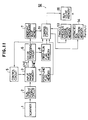
- Figs. 11 to 13 are views showing a vertical component extracting apparatus according to still another embodiment of the present invention.
- a vertical component extracting circuit 52 which is used as the second directional processing means comprises a previous change position memory 53, an extracted run position memory 54 and a run count memory 55.
- the previous change position memory 53 is a memory having the same function as that of the previous change position memory 43.
- the extracted run position memory 54 is a two-dimensional memory having a capacity of storing extracted runs for three lines. The contents of the memory 54 are represented with Run(m, n).
- the run count memory 55 is a memory for storing the number "n" of runs to be extracted and has an initial value of 0.
- the contents Prev(i) of the previous change position memory 53 are initialized.
- a control circuit 51 reads the endpoint coordinate value memory 7 according to the value of a flag of a first run. Supposing endpoint coordinate values K(l 1, k1) and K(l 2, k1) have been read, the data Prev(i) for "i"s satisfying K(l 1, K1) ⁇ i ⁇ K(l 2, k1) are read from the previous change position memory 53. Among the read data, runs with "i"s satisfying K1 - Prev(i) > th ("th" indicating a predetermined run length threshold) are registered as extracted runs.
- this registration is carried out by reading "n” from the run count memory 55, by incrementing the value, and by registering a column number "i” into a Run(1, n) of the extracted run position memory 54, Prev(i) into a Run(2, n) and k-1 into a Run(3, n).
- a column number "i” of the extracted run is registered into the Run(1, n), a starting point line position of the extracted run into the Run(2, n), and an endpoint line position of the extracted run into the Run(3, n).
- Prev(i) are read and, for all "i"s satisfying kmax + 1 - Prev(i) > th among "i"s satisfying Prev(i) > 0, the line count memory 55 is read and incremented while a column number "i" is registered into a Run(1, n), a Prev(i) into a Run(2, n) and the kmax into a Run(3, n) to complete the operation.
- vertical runs having run lengths longer than the predetermined run length are extracted as shown in Fig. 12.
- the contents of the extracted run position memory 54 are as shown in Fig. 13.
- run length codes for a first direction are subjected to an exclusive OR operation to find endpoint coordinate values for a second direction which is different from the first direction.
- an optional image process is carried out for the second direction so that a high-speed image processing is realized with a small capacity memory.
Landscapes
- Engineering & Computer Science (AREA)
- Multimedia (AREA)
- Signal Processing (AREA)
- Physics & Mathematics (AREA)
- General Physics & Mathematics (AREA)
- Theoretical Computer Science (AREA)
- Image Processing (AREA)
- Compression Of Band Width Or Redundancy In Fax (AREA)
- Image Analysis (AREA)
- Editing Of Facsimile Originals (AREA)
Claims (16)
- Dispositif de traitement d'image pour exécuter un codage de longueur de série suivant une première direction sur des données d'image originales afin d'obtenir des données d'image d'entrée et pour effectuer un traitement d'image suivant une seconde direction sur les données d'image d'entrée obtenues, ledit dispositif comprenant(a) un moyen de codage de longueur de série (2) pour effectuer un codage de longueur de série en codant des séries noires et blanches suivant une première direction sur les données d'image originales (31) afin d'obtenir les données d'image d'entrée (32),(b) un moyen de mémoire de données d'image d'entrée (3) pour mémoriser les données d'image d'entrée (32) obtenues en effectuant le codage de longueur de série suivant ladite première direction sur les données d'image originales (31) par ledit moyen de codage de longueur de série (2), et(c) un moyen de lecture (5) pour lire de façon séquentielle, à partir dudit moyen de mémoire (3), des données d'image d'entrée (32) de groupes de deux lignes j) qui sont contigües l'une à l'autre suivant la seconde direction,caractérisé par
(d) un moyen de traitement par OU exclusif (6) pour déterminer les positions de points d'extrémité dans les séries noires et blanches suivant la seconde direction en effectuant des opérations d'OU exclusif entre les données de l'une desdites deux lignes et l'autre desdites deux lignes, lues par ledit moyen de lecture (5). - Dispositif de traitement d'image selon la revendication 1, dans lequel ladite première direction et ladite seconde direction sont perpendiculaires l'une à l'autre.
- Dispositif de traitement d'image selon la revendication 2, dans lequel ladite première direction est horizontale et la seconde direction est verticale.
- Dispositif de traitement d'image selon l'une quelconque des revendications précédentes, dans lequel ledit moyen de traitement par OU exclusif (6) comprend- un moyen de détection de position de points d'extrémité (21, 22) pour détecter les positions des points d'extrémité dans les séries noires et blanches suivant la première direction, et- un moyen de mémoire de position de points d'extrémité (23, 24, 7) pour mémoriser les positions de points d'extrémité de chaque deux lignes contigües (j-1, j) détectées par ledit moyen de détection de position de points d'extrémité (21, 22), en tant que données indicatives des positions de points d'extrémité dans les séries noires et blanches suivant la seconde direction existant entre lesdites chaque deux lignes contigües.
- Dispositif de traitement d'image selon la revendication 4, dans lequel ledit moyen de traitement OU exclusif (6) comprend un moyen de tri (25) relié audit moyen de mémoire de position de points d'extrémité (23, 24) afin d'abandonner leurs valeurs lorsqu'elles sont égales, et afin de les trier lorsqu'elles sont différentes.
- Dispositif de traitement d'image selon la revendication 1, dans lequel un second moyen de traitement directionnel (10; 42; 52) est prévu pour effectuer un traitement d'image prédéterminé suivant la seconde direction conformément aux positions de points d'extrémité dans les séries noires et blanches suivant la seconde direction, déterminées par ledit moyen de traitement par OU exclusif (6).
- Dispositif de traitement d'image selon la revendication 6, dans lequel ledit second moyen de traitement directionnel (10) comprend un second circuit de traitement de série directionnelle (13) pour effectuer un codage de longueur de série suivant la seconde direction des données d'image originales (31).
- Dispositif de traitement d'image selon la revendication 6 ou la revendication 7, dans lequel ledit second moyen de traitement directionnel (10) comprend un second circuit de détection de saillie directionnelle (42) afin d'obtenir des saillies suivant la seconde direction des données d'image originales (31) en accumulant des distances de bit entre les positions de points d'extrémité dans les séries noires et blanches suivant la seconde direction en fonction de chacune des positions dans la première direction.
- Dispositif de traitement d'image selon l'une quelconque des revendications 6 à 8, dans lequel ledit second moyen de traitement directionnel (10) comprend un second circuit d'extraction de composant de ligne directionnel (52) afin d'extraire des seconds composants de ligne directionnel suivant la seconde direction des données d'image originales (31) en extrayant des distances de bits, présentant une longueur en bits plus grande qu'une longueur prédéterminée, entre des positions de points d'extrémité dans les séries noires et blanches suivant la seconde direction.
- Procédé de traitement d'image pour effectuer un codage de longueur de série suivant une première direction de données d'image originales afin d'obtenir des données d'image d'entrée et pour effectuer un traitement d'image suivant une seconde direction sur les données d'image d'entrée obtenues, ledit procédé comprenant les étapes consistant à(a) coder les données d'image originales (31) au moyen des codes de longueur de série pour les séries noires et blanches suivant une première direction sur les données d'image originales (31) afin d'obtenir les données d'image d'entrée (32),(b) mémoriser les données d'image d'entrée (32) dans un moyen de mémoire de données d'image d'entrée, et(c) lire de façon séquentielle, à partir dudit moyen de mémoire (3), les données d'image d'entrée (32) de groupes de deux lignes (j-1, j) qui sont contigües l'une à l'autre suivant la seconde direction, par un moyen de lecture,caractérisé par
(d) l'exécution d'opérations de OU exclusif entre les données de l'une des deux lignes et de l'autre desdites deux lignes lues par ledit moyen de lecture afin de déterminer les positions de points d'extrémité dans les séries noires et blanches suivant la seconde direction. - Procédé selon la revendication 10, comprenant en outre l'étape consistant à
(e) effectuer un traitement d'image prédéterminé suivant la seconde direction conformément aux positions de points d'extrémité déterminées dans les séries noires et blanches suivant la seconde direction. - Procédé selon la revendication 10 ou la revendication 11, dans lequel l'étape (d) comprend les étapes consistant à- détecter les positions de points d'extrémité dans les séries noires et blanches suivant la première direction de chacune des deux lignes entrées (j-1, j) des données d'image originales (31) par un moyen de détection de positions de points d'extrémité, et- mémoriser les positions de points d'extrémité de chaque deux lignes contigües détectées par ledit moyen de détection de positions de points d'extrémité en tant que données indicatives des positions de points d'extrémité dans les séries noires et blanches suivant la seconde direction existant entre lesdites chaque deux lignes contigües.
- Procédé selon les revendications 11 ou 12, dans lequel ledit traitement d'image prédéterminé dans ladite étape (e) est un traitement consistant à effectuer un codage de longueur de série suivant la seconde direction des données d'image originales (31).
- Procédé selon les revendications 11 ou 12, dans lequel ledit traitement d'image prédéterminé dans ladite étape (e) est un traitement consistant à obtenir des saillies suivant la seconde direction des données d'image originales (31) en accumulant des distances de bits entre les positions de points d'extrémité dans les séries noires et blanches suivant la seconde direction par rapport à chaque position dans la première direction.
- Procédé selon la revendication 11 ou la revendication 12, dans lequel ledit traitement d'image prédéterminé dans ladite étape (e) est un traitement consistant à extraire des seconds composants de ligne directionnelle suivant la seconde direction des données d'image originales en extrayant des distances de bits, présentant une longueur en bits plus grande qu'une longueur prédéterminée, entre les positions de points d'extrémité dans les séries noires et blanches suivant la seconde direction.
- Procédé selon l'une quelconque des revendications 10 à 15, dans lequel la première direction est horizontale et la seconde direction est verticale.
Applications Claiming Priority (2)
| Application Number | Priority Date | Filing Date | Title |
|---|---|---|---|
| JP62246138A JP2670273B2 (ja) | 1987-09-30 | 1987-09-30 | 画像処理装置 |
| JP246138/87 | 1987-09-30 |
Publications (3)
| Publication Number | Publication Date |
|---|---|
| EP0309655A2 EP0309655A2 (fr) | 1989-04-05 |
| EP0309655A3 EP0309655A3 (fr) | 1991-04-03 |
| EP0309655B1 true EP0309655B1 (fr) | 1995-07-26 |
Family
ID=17144045
Family Applications (1)
| Application Number | Title | Priority Date | Filing Date |
|---|---|---|---|
| EP88110385A Expired - Lifetime EP0309655B1 (fr) | 1987-09-30 | 1988-06-29 | Appareil et procédé de traitement d'images |
Country Status (6)
| Country | Link |
|---|---|
| US (1) | US4893187A (fr) |
| EP (1) | EP0309655B1 (fr) |
| JP (1) | JP2670273B2 (fr) |
| KR (1) | KR920005196B1 (fr) |
| CA (1) | CA1306296C (fr) |
| DE (1) | DE3854216T2 (fr) |
Families Citing this family (15)
| Publication number | Priority date | Publication date | Assignee | Title |
|---|---|---|---|---|
| JPH0831130B2 (ja) * | 1989-05-12 | 1996-03-27 | 大日本スクリーン製造株式会社 | 線画像の処理方法 |
| JPH088642B2 (ja) * | 1989-07-27 | 1996-01-29 | 富士通株式会社 | 網点画像データ圧縮装置 |
| US5293251A (en) * | 1991-10-31 | 1994-03-08 | Comsat Corporation | Encoding/decoding system with two-stages of encoding/decoding |
| JPH05183765A (ja) * | 1991-12-27 | 1993-07-23 | Canon Inc | データ処理システム及び該システムに用いることが可能な装置 |
| EP0571170B1 (fr) * | 1992-05-18 | 2000-04-12 | Canon Kabushiki Kaisha | Méthode de codage et méthode de décodage |
| CA2110242C (fr) * | 1992-11-27 | 2001-01-23 | Masayoshi Aihara | Telecopieur portatif |
| US5889893A (en) * | 1996-03-27 | 1999-03-30 | Xerox Corporation | Method and apparatus for the fast rotation of an image |
| US6198508B1 (en) * | 1996-11-01 | 2001-03-06 | Samsung Electronics Co., Ltd. | Method of encoding picture data and apparatus therefor |
| US6870944B1 (en) * | 1999-06-08 | 2005-03-22 | Sony Corporation | Image processing apparatus, image processing method, and storage medium |
| US6535150B1 (en) | 1999-09-03 | 2003-03-18 | Whamtech, Inc. | Method and apparatus for implementing run-length compression |
| JP2002036636A (ja) * | 2000-07-19 | 2002-02-06 | Mitsubishi Electric Corp | 画像データ変換装置および画像データ変換方法 |
| US7920749B1 (en) | 2006-12-20 | 2011-04-05 | Nvidia Corporation | Modified high dynamic range color decompression |
| US7742646B1 (en) * | 2006-12-20 | 2010-06-22 | Nvidia Corporation | Modified high dynamic range color decompression |
| US7983498B1 (en) | 2007-08-06 | 2011-07-19 | Nvidia Corporation | Low dynamic range 3-channel color compression |
| US20250301161A1 (en) * | 2024-03-22 | 2025-09-25 | Microsoft Technology Licensing, Llc | Encoding a binary image |
Family Cites Families (4)
| Publication number | Priority date | Publication date | Assignee | Title |
|---|---|---|---|---|
| JPS5412515A (en) * | 1977-06-29 | 1979-01-30 | Ricoh Co Ltd | Data compression system |
| IT1155650B (it) * | 1982-03-19 | 1987-01-28 | Olivetti & Co Spa | Metodo ed apparecchiatura di compressione e decompressione di informazioni digitali di immagini |
| JPS61102872A (ja) * | 1984-10-24 | 1986-05-21 | インタ−ナショナル ビジネス マシ−ンズ コ−ポレ−ション | 2レベル・イメ−ジ・デ−タの処理方法 |
| US4658430A (en) * | 1984-12-27 | 1987-04-14 | International Business Machines Corp. | System for rotating binary images |
-
1987
- 1987-09-30 JP JP62246138A patent/JP2670273B2/ja not_active Expired - Fee Related
-
1988
- 1988-06-13 US US07/205,774 patent/US4893187A/en not_active Expired - Lifetime
- 1988-06-29 DE DE3854216T patent/DE3854216T2/de not_active Expired - Fee Related
- 1988-06-29 EP EP88110385A patent/EP0309655B1/fr not_active Expired - Lifetime
- 1988-07-11 CA CA000571641A patent/CA1306296C/fr not_active Expired - Lifetime
- 1988-09-30 KR KR1019880012754A patent/KR920005196B1/ko not_active Expired
Also Published As
| Publication number | Publication date |
|---|---|
| EP0309655A3 (fr) | 1991-04-03 |
| JPS6489760A (en) | 1989-04-04 |
| CA1306296C (fr) | 1992-08-11 |
| JP2670273B2 (ja) | 1997-10-29 |
| DE3854216D1 (de) | 1995-08-31 |
| EP0309655A2 (fr) | 1989-04-05 |
| KR890006054A (ko) | 1989-05-18 |
| KR920005196B1 (ko) | 1992-06-29 |
| US4893187A (en) | 1990-01-09 |
| DE3854216T2 (de) | 1996-01-25 |
Similar Documents
| Publication | Publication Date | Title |
|---|---|---|
| US4893187A (en) | Image processing apparatus | |
| US4992650A (en) | Method and apparatus for barcode recognition in a digital image | |
| US6546136B1 (en) | Matching CCITT compressed document images | |
| US5177622A (en) | Method and apparatus for detecting run length of two successive pixels and subjecting run length to universal coding | |
| US4441208A (en) | Picture information processing and storing device | |
| EP0309166A2 (fr) | Système de traitement d'image | |
| EP0552791B1 (fr) | Appareil et méthode pour l'extraction de données de contours et l'encodage de données d'images utilisant ces données de contours | |
| US5708731A (en) | Pattern matching method with pixel vectors | |
| JP2962518B2 (ja) | 画像データの符号化装置 | |
| US6574367B1 (en) | Method and apparatus for pattern matching encoding | |
| JPH05145770A (ja) | 符号・復号化装置 | |
| US5091977A (en) | Image data compression method using a run prediction technique | |
| EP0034187B1 (fr) | Systeme de retablissement de donnees comprimees | |
| US4121258A (en) | Method for coding facsimile signal | |
| US6526172B1 (en) | Coding method and coder using pattern matching | |
| US5453843A (en) | Method for fast data compression of half tone images with the use of pre-assigned codes | |
| US3970991A (en) | Character recognition system | |
| JP3095071B2 (ja) | パタンマッチング符号化装置、及びその符号化方法 | |
| US6912320B2 (en) | Data decompressing method, data decompressing unit, and computer-readable storage medium storing data decompressing program | |
| JPH05151349A (ja) | 画像データ圧縮方法および符号化回路 | |
| JP3433276B2 (ja) | 画像信号圧縮方法及び装置,画像信号復元方法及び装置,画像信号圧縮・復元方法及び装置,並びにプリンタ装置 | |
| US20020009236A1 (en) | Image data conversion device and image data conversion method for converting the order of pixels | |
| CA1199407A (fr) | Systeme de mesure des transitions pour la reconnaissance de l'ecriture cursive | |
| JPH04270569A (ja) | 画像処理装置におけるデータ圧縮方式 | |
| JP2001298624A (ja) | データ圧縮処理方法及びその装置 |
Legal Events
| Date | Code | Title | Description |
|---|---|---|---|
| PUAI | Public reference made under article 153(3) epc to a published international application that has entered the european phase |
Free format text: ORIGINAL CODE: 0009012 |
|
| 17P | Request for examination filed |
Effective date: 19880629 |
|
| AK | Designated contracting states |
Kind code of ref document: A2 Designated state(s): DE FR GB IT |
|
| PUAL | Search report despatched |
Free format text: ORIGINAL CODE: 0009013 |
|
| AK | Designated contracting states |
Kind code of ref document: A3 Designated state(s): DE FR GB IT |
|
| 17Q | First examination report despatched |
Effective date: 19930222 |
|
| GRAA | (expected) grant |
Free format text: ORIGINAL CODE: 0009210 |
|
| AK | Designated contracting states |
Kind code of ref document: B1 Designated state(s): DE FR GB IT |
|
| ET | Fr: translation filed | ||
| REF | Corresponds to: |
Ref document number: 3854216 Country of ref document: DE Date of ref document: 19950831 |
|
| ITF | It: translation for a ep patent filed | ||
| PLBE | No opposition filed within time limit |
Free format text: ORIGINAL CODE: 0009261 |
|
| STAA | Information on the status of an ep patent application or granted ep patent |
Free format text: STATUS: NO OPPOSITION FILED WITHIN TIME LIMIT |
|
| 26N | No opposition filed | ||
| REG | Reference to a national code |
Ref country code: GB Ref legal event code: 746 Effective date: 19981010 |
|
| REG | Reference to a national code |
Ref country code: FR Ref legal event code: D6 |
|
| PGFP | Annual fee paid to national office [announced via postgrant information from national office to epo] |
Ref country code: FR Payment date: 19990610 Year of fee payment: 12 |
|
| PGFP | Annual fee paid to national office [announced via postgrant information from national office to epo] |
Ref country code: GB Payment date: 19990623 Year of fee payment: 12 |
|
| PGFP | Annual fee paid to national office [announced via postgrant information from national office to epo] |
Ref country code: DE Payment date: 19990706 Year of fee payment: 12 |
|
| PG25 | Lapsed in a contracting state [announced via postgrant information from national office to epo] |
Ref country code: GB Free format text: LAPSE BECAUSE OF NON-PAYMENT OF DUE FEES Effective date: 20000629 |
|
| GBPC | Gb: european patent ceased through non-payment of renewal fee |
Effective date: 20000629 |
|
| PG25 | Lapsed in a contracting state [announced via postgrant information from national office to epo] |
Ref country code: FR Free format text: LAPSE BECAUSE OF NON-PAYMENT OF DUE FEES Effective date: 20010228 |
|
| REG | Reference to a national code |
Ref country code: FR Ref legal event code: ST |
|
| PG25 | Lapsed in a contracting state [announced via postgrant information from national office to epo] |
Ref country code: DE Free format text: LAPSE BECAUSE OF NON-PAYMENT OF DUE FEES Effective date: 20010403 |
|
| PG25 | Lapsed in a contracting state [announced via postgrant information from national office to epo] |
Ref country code: IT Free format text: LAPSE BECAUSE OF NON-PAYMENT OF DUE FEES Effective date: 20050629 |