EP0309678A1 - Verfahren zum Fertigen eines Kugelkükens für einen Kugelhahn - Google Patents
Verfahren zum Fertigen eines Kugelkükens für einen Kugelhahn Download PDFInfo
- Publication number
- EP0309678A1 EP0309678A1 EP88112190A EP88112190A EP0309678A1 EP 0309678 A1 EP0309678 A1 EP 0309678A1 EP 88112190 A EP88112190 A EP 88112190A EP 88112190 A EP88112190 A EP 88112190A EP 0309678 A1 EP0309678 A1 EP 0309678A1
- Authority
- EP
- European Patent Office
- Prior art keywords
- plug
- ball
- ball plug
- housing
- throttle opening
- Prior art date
- Legal status (The legal status is an assumption and is not a legal conclusion. Google has not performed a legal analysis and makes no representation as to the accuracy of the status listed.)
- Granted
Links
- 238000000034 method Methods 0.000 title claims abstract description 10
- 239000000919 ceramic Substances 0.000 claims abstract description 6
- 238000004519 manufacturing process Methods 0.000 claims abstract description 6
- 230000015572 biosynthetic process Effects 0.000 abstract 1
- 210000000056 organ Anatomy 0.000 abstract 1
- 229910001141 Ductile iron Inorganic materials 0.000 description 2
- 230000006978 adaptation Effects 0.000 description 2
- 238000010276 construction Methods 0.000 description 2
- 239000000463 material Substances 0.000 description 2
- 238000007789 sealing Methods 0.000 description 2
- 229910052581 Si3N4 Inorganic materials 0.000 description 1
- 238000005266 casting Methods 0.000 description 1
- 229910010293 ceramic material Inorganic materials 0.000 description 1
- 210000004907 gland Anatomy 0.000 description 1
- 239000013067 intermediate product Substances 0.000 description 1
- 238000000465 moulding Methods 0.000 description 1
- TWNQGVIAIRXVLR-UHFFFAOYSA-N oxo(oxoalumanyloxy)alumane Chemical compound O=[Al]O[Al]=O TWNQGVIAIRXVLR-UHFFFAOYSA-N 0.000 description 1
- HBMJWWWQQXIZIP-UHFFFAOYSA-N silicon carbide Chemical compound [Si+]#[C-] HBMJWWWQQXIZIP-UHFFFAOYSA-N 0.000 description 1
- 229910010271 silicon carbide Inorganic materials 0.000 description 1
- HQVNEWCFYHHQES-UHFFFAOYSA-N silicon nitride Chemical compound N12[Si]34N5[Si]62N3[Si]51N64 HQVNEWCFYHHQES-UHFFFAOYSA-N 0.000 description 1
- 238000003860 storage Methods 0.000 description 1
Images
Classifications
-
- F—MECHANICAL ENGINEERING; LIGHTING; HEATING; WEAPONS; BLASTING
- F16—ENGINEERING ELEMENTS AND UNITS; GENERAL MEASURES FOR PRODUCING AND MAINTAINING EFFECTIVE FUNCTIONING OF MACHINES OR INSTALLATIONS; THERMAL INSULATION IN GENERAL
- F16K—VALVES; TAPS; COCKS; ACTUATING-FLOATS; DEVICES FOR VENTING OR AERATING
- F16K5/00—Plug valves; Taps or cocks comprising only cut-off apparatus having at least one of the sealing faces shaped as a more or less complete surface of a solid of revolution, the opening and closing movement being predominantly rotary
- F16K5/06—Plug valves; Taps or cocks comprising only cut-off apparatus having at least one of the sealing faces shaped as a more or less complete surface of a solid of revolution, the opening and closing movement being predominantly rotary with plugs having spherical surfaces; Packings therefor
- F16K5/0605—Plug valves; Taps or cocks comprising only cut-off apparatus having at least one of the sealing faces shaped as a more or less complete surface of a solid of revolution, the opening and closing movement being predominantly rotary with plugs having spherical surfaces; Packings therefor with particular plug arrangements, e.g. particular shape or built-in means
-
- F—MECHANICAL ENGINEERING; LIGHTING; HEATING; WEAPONS; BLASTING
- F16—ENGINEERING ELEMENTS AND UNITS; GENERAL MEASURES FOR PRODUCING AND MAINTAINING EFFECTIVE FUNCTIONING OF MACHINES OR INSTALLATIONS; THERMAL INSULATION IN GENERAL
- F16K—VALVES; TAPS; COCKS; ACTUATING-FLOATS; DEVICES FOR VENTING OR AERATING
- F16K27/00—Construction of housing; Use of materials therefor
- F16K27/06—Construction of housing; Use of materials therefor of taps or cocks
- F16K27/067—Construction of housing; Use of materials therefor of taps or cocks with spherical plugs
Definitions
- the invention relates to a method for manufacturing a ball plug for a ball valve and a ball plug with the features of the preamble of claims 1 and 2.
- a sleeve-shaped control element is inserted into the through hole of the ball plug.
- This control element is open at one end, while the throttle opening is formed in the other end.
- the control element provided with the throttle opening can also be disc-shaped and inserted into the housing.
- the ball plug contains a through hole with a constant inside diameter.
- the throttle openings in the control elements have different control characteristics. To switch to a different control characteristic, the control elements must therefore be replaced, so that different control elements have to be manufactured and stored depending on the application.
- Ball valves with ceramic ball valves are also known, in which the ball valve is provided with an opening corresponding to the control characteristic in order to regulate the mass flow. This is constant in the entire diameter, so that a change in the control characteristic can only be carried out by replacing the ball plug.
- the invention has for its object to develop a ball valve that can be used for all areas of control and shut-off without changing the number of essential structural components.
- the process according to the invention creates an intermediate product in a first process step, which can be used for all applications.
- the adaptation to the special application is carried out by a minor processing in the second step.
- the method relates in particular to the manufacture of ball plugs from a ceramic material such as aluminum oxide or silicon carbide or nitride.
- the ball plug can also be made of a metallic casting material, e.g. Ductile iron, be made.
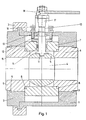
- the ball valve consists of a metallic housing 1 and a metallic housing flange 2, which are designed as non-pressure-bearing parts and are held together by a clamping ring 3. Pipe sockets (not shown) are screwed onto the housing 1 and the housing flange 2.
- a ball plug 5 provided with a through hole 4 is rotatably arranged.
- the ball plug 5 seals from the seat surfaces of two annular seat housings 6, which are enclosed by the housing 1 and the housing flange 2.
- the ball plug 5 is surrounded by a housing center piece 7, which rests on one shoulder of the seat housing 6.
- the housing center piece 7 and the seat housing 6, like the ball valve 5, are made of ceramic. They have a cylindrical shape and are therefore designed to be suitable for ceramics.
- the seat housings 6 are sealed with respect to the housing center piece 7 and with respect to the housing 1 and the housing flange 2 by O-rings 8, 9. The metallic parts of the ball valve therefore do not come into contact with the medium flowing through.
- the housing center piece 7 is provided with a bore through which a spindle 10 is passed.
- the spindle 10 engages in a groove 11 of the ball plug 5 and is held in the housing 1 by means of two rings 12, 13.
- the passage of the spindle 10 through the housing center piece 7 is sealed by sealing sleeves 14, which are pressed on using a stuffing box gland 15 with the aid of screws 16.
- the end of the spindle 10 protruding from the housing 1 is connected to a hand lever 18 via a connecting spindle 17.
- the ball valve can serve as a shut-off device and have a through bore 4.
- the ball valve can also be used as a throttle element by providing the ball plug 5 with a throttle opening 19 of any control characteristic.
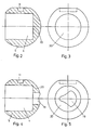
- the ball plug 5 is manufactured in the following way. According to FIG. 2, the ball plug 5 is initially given a bottom 20 during the molding, which closes the through hole 4 of uniform diameter on one side. The bottom 20 is severed in a second process step, completely if the ball plug is to perform a shut-off function (FIG. 1). As shown in FIGS. 4 and 5, the throttle opening 19 is subsequently worked out from the bottom 20 when used as a throttle element.
- the same subsequent adaptation of the ball plug 4 to the intended application is also carried out when the ball plug 4 is cast, for example, from nodular cast iron.
- the ceramic parts of the ball valve shown in Fig.1 are omitted. Instead, metallic sealing rings or plastic ones are inserted into the housing, against which the ball plug seals.
Landscapes
- Engineering & Computer Science (AREA)
- General Engineering & Computer Science (AREA)
- Mechanical Engineering (AREA)
- Taps Or Cocks (AREA)
- Lift Valve (AREA)
- Valve Housings (AREA)
Abstract
Description
- Die Erfindung betrifft ein Verfahren zum Fertigen eines Kugelkükens für einen Kugelhahn und ein Kugelküken mit den Merkmalen des Oberbegriffes der Patentansprüche 1 und 2.
- Bei einem bekannten Kugelhahn (DE-AS 27 32 672) ist in die Durchgangsbohrung des Kugelkükens ein hülsenförmiges Steuerelement eingefügt. Dieses Steuerelement ist an einem Ende offen, während in dem anderen Ende die Drosselöffnung gebildet ist. Das mit der Drosselöffnung versehene Steuerelement kann auch scheibenförmig ausgebildet und in das Gehäuse eingesetzt sein. In diesem Fall enthält das Kugelküken eine durchgehende Durchgangsbohrung von gleichbleibendem Innendurchmesser. Die Drosselöffnungen in den Steuerelementen weisen unterschiedliche Steuercharakteristiken auf. Zur Umstellung auf eine andere Steuercharakteristik müssen daher die Steuerelemente ausgetauscht werden, so daß je nach Anwendungszweck unterschiedliche Steuerelemente gefertigt und gelagert werden müssen.
- Es sind weiterhin Kugelhähne mit aus Keramik bestehenden Kugelküken bekannt, bei denen zur Regelung des Massenstromes das Kugelküken mit einer der Regelcharakteristik entsprechenden Öffnung versehen ist. Diese ist im gesamten Durchmesser gleichbleibend, so daß eine Veränderung der Regelcharakteristik nur durch Auswechseln des Kugelkükens durchführbar ist. Damit wird für die unterschiedlichen Anwendungsgebiete, wie reine Absperrung, Regelung mit linerarer oder gleichprozentiger Kennlinie, die Fertigung und Lagerung von unterschiedlichen Kugelküken mit entsprechenden Öffnungen notwendig, da diese Öffnungen nur im Herstellungsprozeß des Kugelkükens angebracht werden können und eine nachträgliche Bearbeitung nicht möglich ist.
- Der Erfindung liegt die Aufgabe zugrunde, einen Kugelhahn zu entwickeln, der ohne Veränderung der Zahl der wesentlichen Konstruktionsbauteile für alle Anwendungsgebiete der Regelung und Absperrung einsetzbar ist.
- Diese Aufgabe wird durch ein Verfahren mit den Merkmalen des Anspruches 1 gelöst. Ein nach diesem Verfahren hergestelltes Kugelküken ist durch den Anspruch 2 gekennzeichnet.
- Durch das erfindungsgemäße Verfahren wird in einem ersten Verfahrensschritt ein Zwischenprodukt geschaffen, das für alle Anwendungsfälle einsetzbar ist. Die Anpassung an den speziellen Anwendungsfall erfolgt durch eine geringe Bearbeitung in dem zweiten Verfahrensschritt. Damit ist für eine vorgegebene Ventilgröße nur ein Konstruktionsbauteil erforderlich, um alle Anwendungsfälle abzudecken. Das Verfahren bezieht sich insbesondere auf die Herstellung von Kugelküken aus einem keramischen Werkstoff wie Aluminiumoxid oder Siliziumkarbid oder -nitrid. Das Kugelküken kann auch aus einem metallischen Gußwerkstoff, z.B. Sphäroguß, gefertigt sein.
- Mehrere Ausführungsbeispiele der Erfindung sind in der Zeichnung dargestellt und werden im folgenden näher erläutert. Es zeigen
- Fig. 1 den Längsschnitt durch einen Kugelhahn,
- Fig. 2 den Längsschnitt durch ein Kugelküken mit einem geschlossenen Boden,
- Fig. 3 die Seitenansicht zu Fig. 2,
- Fig. 4 den Längsschnitt durch ein Kugelküken mit einer Drosselöffnung und
- Fig. 5 die Seitenansicht zu Fig. 4.
- Der Kugelhahn besteht aus einem metallischen Gehäuse 1 und einem metallischen Gehäuseflansch 2, die als nicht drucktragende Teile ausgebildet und durch einen Spannring 3 zusammengehalten sind. An das Gehäuse 1 und den Gehäuseflansch 2 sind nicht dargestellte Rohrstutzen angeschraubt.
- Innerhalb des Gehäuses 1 ist ein mit einer Durchgangsbohrung 4 versehenes Kugelküken 5 drehbar angeordnet. Das Kugelküken 5 dichtet an den Sitzflächen zweier ringförmiger Sitzgehäuse 6 ab, die von dem Gehäuse 1 und dem Gehäuseflansch 2 umschlossen sind. Das Kugelküken 5 ist von einem Gehäusemittelstück 7 umgeben, das auf jeweils einer Schulter der Sitzgehäuse 6 ruht. Das Gehäusemittelstück 7 und die Sitzgehäuse 6 bestehen ebenso wie das Kugelküken 5 aus Keramik. Sie haben eine zylindrische Form und sind somit keramikgerecht konzipiert. Die Sitzgehäuse 6 sind gegenüber dem Gehäusemittelstück 7 und gegenüber dem Gehäuse 1 und dem Gehäuseflansch 2 durch O-Ringe 8, 9 abgedichtet. Die metallischen Teile des Kugelhahnes kommen somit mit dem durchströmenden Medium nicht in Berührung.
- Das Gehäusemittelstück 7 ist mit einer Bohrung versehen, durch die eine Spindel 10 hindurchgeführt ist. Die Spindel 10 greift in eine Nut 11 des Kugelkükens 5 ein und ist in dem Gehäuse 1 mit Hilfe von zwei Ringen 12, 13 gehalten. Der Durchtritt der Spindel 10 durch das Gehäusemittelstück 7 ist durch Dichtmanschetten 14 abgedichtet, die über eine Stopfbuchsbrille 15 mit Hilfe von Schrauben 16 angedrückt werden. Das aus dem Gehäuse 1 herausragende Ende der Spindel 10 ist über eine Anschlußspindel 17 mit einem Handhebel 18 verbunden.
- Der Kugelhahn kann, wie in Fig. 1 dargestellt, als Absperrorgan dienen und eine durchgehende Durchgangsbohrung 4 aufweisen. Der Kugelhahn kann auch als Drosselorgan verwendet werden, indem das Kugelküken 5 mit einer Drosselöffnung 19 von beliebiger Steuercharakteristik versehen wird. Um mit möglichst wenigen Konstruktionsteilen für jeden Anwendungszweck auskommen zu können, wird das Kugelküken 5 auf die folgende Weise hergestellt. Gemäß Fig. 2 erhält zunächst das Kugelküken 5 bei der Formung einen Boden 20, der einseitig die Durchgangsbohrung 4 von einheitlichem Durchmesser verschließt. Der Boden 20 wird in einem zweiten Verfahrensschritt durchtrennt, und zwar vollständig, wenn das Kugelküken eine Absperrfunktion ausüben soll (Fig.1). Wie in den Fig. 4 und 5 gezeigt ist, wird bei der Verwendung als Drosselorgan aus dem Boden 20 nachträglich die Drosselöffnung 19 herausgearbeitet.
- Die gleiche nachträgliche Anpassung des Kugelkükens 4 an den vorgesehenen Anwendungsfall wird auch dann vorgenommen, wenn das Kugelküken 4 z.B. aus Sphäroguß gegossen ist. Bei Verwendung eines metallischen Gußwerkstoffes für das Kugelküken 4 entfallen die in Fig.1 dargestellten keramischen Teile des Kugelhahnes. Statt dessen sind metallische Dichtringe oder solche aus Kunststoff in das Gehäuse eingelegt, gegenüber denen das Kugelküken abdichtet.
Claims (3)
Applications Claiming Priority (2)
| Application Number | Priority Date | Filing Date | Title |
|---|---|---|---|
| DE3729255A DE3729255C1 (de) | 1987-09-02 | 1987-09-02 | Kugelkueken |
| DE3729255 | 1987-09-02 |
Publications (2)
| Publication Number | Publication Date |
|---|---|
| EP0309678A1 true EP0309678A1 (de) | 1989-04-05 |
| EP0309678B1 EP0309678B1 (de) | 1990-10-31 |
Family
ID=6335017
Family Applications (1)
| Application Number | Title | Priority Date | Filing Date |
|---|---|---|---|
| EP88112190A Expired - Lifetime EP0309678B1 (de) | 1987-09-02 | 1988-07-28 | Verfahren zum Fertigen eines Kugelkükens für einen Kugelhahn |
Country Status (2)
| Country | Link |
|---|---|
| EP (1) | EP0309678B1 (de) |
| DE (2) | DE3729255C1 (de) |
Cited By (5)
| Publication number | Priority date | Publication date | Assignee | Title |
|---|---|---|---|---|
| EP0864788A4 (de) * | 1996-09-30 | 1999-07-07 | Seikisui Chemical Co Ltd | Kugelhahn |
| WO2001033120A1 (en) * | 1999-11-02 | 2001-05-10 | Cim-Valve Sa | Improved ball valve |
| RU2327919C2 (ru) * | 2002-05-03 | 2008-06-27 | ЭНОЛГАС БОНОМИ С.п.А. | Шаровой клапан с расходомером, установленным непосредственно в шаре |
| RU2334148C1 (ru) * | 2006-11-07 | 2008-09-20 | Александр Павлович Андреев | Клапан регулирующий |
| CH708205A1 (de) * | 2013-06-12 | 2014-12-15 | Belimo Holding Ag | Regelhahn. |
Families Citing this family (4)
| Publication number | Priority date | Publication date | Assignee | Title |
|---|---|---|---|---|
| ITMI20060740A1 (it) * | 2006-04-13 | 2007-10-14 | Vir Valvoindustria Ing Rizzio | Sfera per valvole e relativo metodo di produzione |
| WO2011038246A1 (en) * | 2009-09-25 | 2011-03-31 | Allen Stanley C | Flow control hemispherical wedge valve |
| US9086154B2 (en) * | 2013-04-04 | 2015-07-21 | Hamilton Sundstrand Corporation | Ball shaft for a liquid coolant valve |
| CN104455525A (zh) * | 2014-11-14 | 2015-03-25 | 浙江中控流体技术有限公司 | 流量可调节球阀 |
Citations (4)
| Publication number | Priority date | Publication date | Assignee | Title |
|---|---|---|---|---|
| US1534866A (en) * | 1919-12-22 | 1925-04-21 | Victory Equipment Corp | Valve |
| US2018034A (en) * | 1933-10-02 | 1935-10-22 | Roberts Brass Mfg Company | Pilot regulating cock |
| DE1650419A1 (de) * | 1966-11-28 | 1970-10-22 | Honeywell Inc | Durchgangsventil fuer fluessige oder fliessfaehige Medien |
| DE2654769A1 (de) * | 1976-12-03 | 1978-06-08 | Helbling Ag Ingenieurbueros | Ventil zur geraeuscharmen drosselung stroemender, gasfoermiger medien |
Family Cites Families (1)
| Publication number | Priority date | Publication date | Assignee | Title |
|---|---|---|---|---|
| DE2732672C2 (de) * | 1977-07-20 | 1979-06-21 | Reglerbau Hannemann Gmbh & Co Kg, 4000 Duesseldorf | Kugelhahn |
-
1987
- 1987-09-02 DE DE3729255A patent/DE3729255C1/de not_active Expired
-
1988
- 1988-07-28 EP EP88112190A patent/EP0309678B1/de not_active Expired - Lifetime
- 1988-07-28 DE DE8888112190T patent/DE3860937D1/de not_active Expired - Lifetime
Patent Citations (4)
| Publication number | Priority date | Publication date | Assignee | Title |
|---|---|---|---|---|
| US1534866A (en) * | 1919-12-22 | 1925-04-21 | Victory Equipment Corp | Valve |
| US2018034A (en) * | 1933-10-02 | 1935-10-22 | Roberts Brass Mfg Company | Pilot regulating cock |
| DE1650419A1 (de) * | 1966-11-28 | 1970-10-22 | Honeywell Inc | Durchgangsventil fuer fluessige oder fliessfaehige Medien |
| DE2654769A1 (de) * | 1976-12-03 | 1978-06-08 | Helbling Ag Ingenieurbueros | Ventil zur geraeuscharmen drosselung stroemender, gasfoermiger medien |
Non-Patent Citations (1)
| Title |
|---|
| PATENT ABSTRACTS OF JAPAN, Unexamined Applications, Field M, Band 7, Nr. 261, 19. November 1983 The Patent Office Japanese Government seite 67 M 257 * Kokai-Nr. 58-142 080 (Yoshio Kajita) * * |
Cited By (8)
| Publication number | Priority date | Publication date | Assignee | Title |
|---|---|---|---|---|
| EP0864788A4 (de) * | 1996-09-30 | 1999-07-07 | Seikisui Chemical Co Ltd | Kugelhahn |
| US6021812A (en) * | 1996-09-30 | 2000-02-08 | Sekisui Kagaku Kogyo Kabushiki Kaisha & Ichinose Co., Ltd. | Ball plug valve |
| WO2001033120A1 (en) * | 1999-11-02 | 2001-05-10 | Cim-Valve Sa | Improved ball valve |
| RU2327919C2 (ru) * | 2002-05-03 | 2008-06-27 | ЭНОЛГАС БОНОМИ С.п.А. | Шаровой клапан с расходомером, установленным непосредственно в шаре |
| RU2334148C1 (ru) * | 2006-11-07 | 2008-09-20 | Александр Павлович Андреев | Клапан регулирующий |
| CH708205A1 (de) * | 2013-06-12 | 2014-12-15 | Belimo Holding Ag | Regelhahn. |
| WO2014198367A1 (de) * | 2013-06-12 | 2014-12-18 | Belimo Holding Ag | Regelhahn |
| US9903481B2 (en) | 2013-06-12 | 2018-02-27 | Belimo Holding Ag | Control valve |
Also Published As
| Publication number | Publication date |
|---|---|
| EP0309678B1 (de) | 1990-10-31 |
| DE3729255C1 (de) | 1988-11-03 |
| DE3860937D1 (de) | 1990-12-06 |
Similar Documents
| Publication | Publication Date | Title |
|---|---|---|
| DE69011787T2 (de) | Schiebeventil mit Scherwirkung. | |
| DE4328709A1 (de) | Elektromagnetventil | |
| EP0309678B1 (de) | Verfahren zum Fertigen eines Kugelkükens für einen Kugelhahn | |
| DE69500432T2 (de) | Stangendurchführung, insbesondere für Transformator | |
| DE69410565T2 (de) | Kugelhahn für ein Kühlsystem | |
| EP0477575A1 (de) | US-Wandler, insbesondere zur Luft- und Gasdurchflussmessung, und Verfahren zur Herstellung desselben | |
| DE2206766C3 (de) | Steuerschieberventil | |
| DE3800706C2 (de) | Bausatz für eine Wellendichtung, insbesondere an einem Stevenrohr eines Schiffes | |
| DE3106571A1 (de) | Schwimmende dichtscheibe und verfahren zur herstellung derselben | |
| DE69013042T2 (de) | Ventil mit eingekapselten Balgen für Gas von höchster Reinheit. | |
| EP0220358B1 (de) | Sanitäres Ventil | |
| DE69602480T2 (de) | Ausgleichverfahren eines Ventilspiels | |
| DE10037117C2 (de) | Ventillkolben für Mehrwegeventile | |
| DE68911925T2 (de) | Ventil mit auswechselbarem Einsatzstück. | |
| DE2849779A1 (de) | Drosselklappenventil und verfahren zur herstellung desselben | |
| DE3908859A1 (de) | Kugelschaltventil, insbesondere fuer den chopperbetrieb | |
| DE3110839C2 (de) | Armatur zum Leiten und/oder Regeln von Medienströmen | |
| DE102019119889A1 (de) | Verbindungsanordnung zwischen einer Steuereinrichtung und einem Anschlussflansch sowie Steuereinrichtung, Anschlussflansch und Steckbolzen für die Verbindungsanordnung | |
| DE3537779C1 (en) | Valve | |
| EP0276416A1 (de) | Allseitiges schwenkbares, strahlverstellbares Auslaufmundstück für Wasserauslaufventile | |
| DE3203533A1 (de) | Hydraulisches einbauventil | |
| DE3131943C2 (de) | Absperrschieber mit bei der Betätigung im Normalbetrieb axial feststehender Gewindespindel | |
| DE2116188B2 (de) | Steuerschieberventil | |
| DE69006355T2 (de) | Absperrventil. | |
| DE4120292A1 (de) | Ventil, insbesondere stetigventil fuer pneumatische medien |
Legal Events
| Date | Code | Title | Description |
|---|---|---|---|
| PUAI | Public reference made under article 153(3) epc to a published international application that has entered the european phase |
Free format text: ORIGINAL CODE: 0009012 |
|
| 17P | Request for examination filed |
Effective date: 19890113 |
|
| AK | Designated contracting states |
Kind code of ref document: A1 Designated state(s): BE CH DE FR GB IT LI NL |
|
| 17Q | First examination report despatched |
Effective date: 19891010 |
|
| GRAA | (expected) grant |
Free format text: ORIGINAL CODE: 0009210 |
|
| AK | Designated contracting states |
Kind code of ref document: B1 Designated state(s): BE CH DE FR GB IT LI NL |
|
| REF | Corresponds to: |
Ref document number: 3860937 Country of ref document: DE Date of ref document: 19901206 |
|
| ET | Fr: translation filed | ||
| ITF | It: translation for a ep patent filed | ||
| GBT | Gb: translation of ep patent filed (gb section 77(6)(a)/1977) | ||
| PLBE | No opposition filed within time limit |
Free format text: ORIGINAL CODE: 0009261 |
|
| STAA | Information on the status of an ep patent application or granted ep patent |
Free format text: STATUS: NO OPPOSITION FILED WITHIN TIME LIMIT |
|
| 26N | No opposition filed | ||
| PGFP | Annual fee paid to national office [announced via postgrant information from national office to epo] |
Ref country code: GB Payment date: 19930507 Year of fee payment: 6 |
|
| PGFP | Annual fee paid to national office [announced via postgrant information from national office to epo] |
Ref country code: DE Payment date: 19930521 Year of fee payment: 6 |
|
| PGFP | Annual fee paid to national office [announced via postgrant information from national office to epo] |
Ref country code: BE Payment date: 19930607 Year of fee payment: 6 |
|
| PGFP | Annual fee paid to national office [announced via postgrant information from national office to epo] |
Ref country code: FR Payment date: 19930615 Year of fee payment: 6 |
|
| PGFP | Annual fee paid to national office [announced via postgrant information from national office to epo] |
Ref country code: CH Payment date: 19930617 Year of fee payment: 6 |
|
| PGFP | Annual fee paid to national office [announced via postgrant information from national office to epo] |
Ref country code: NL Payment date: 19930731 Year of fee payment: 6 |
|
| PG25 | Lapsed in a contracting state [announced via postgrant information from national office to epo] |
Ref country code: GB Effective date: 19940728 |
|
| PG25 | Lapsed in a contracting state [announced via postgrant information from national office to epo] |
Ref country code: LI Effective date: 19940731 Ref country code: CH Effective date: 19940731 Ref country code: BE Effective date: 19940731 |
|
| BERE | Be: lapsed |
Owner name: DEUTSCHE BABCOCK WERKE A.G. Effective date: 19940731 |
|
| PG25 | Lapsed in a contracting state [announced via postgrant information from national office to epo] |
Ref country code: NL Effective date: 19950201 |
|
| NLV4 | Nl: lapsed or anulled due to non-payment of the annual fee | ||
| GBPC | Gb: european patent ceased through non-payment of renewal fee |
Effective date: 19940728 |
|
| PG25 | Lapsed in a contracting state [announced via postgrant information from national office to epo] |
Ref country code: FR Effective date: 19950331 |
|
| REG | Reference to a national code |
Ref country code: CH Ref legal event code: PL |
|
| PG25 | Lapsed in a contracting state [announced via postgrant information from national office to epo] |
Ref country code: DE Effective date: 19950401 |
|
| REG | Reference to a national code |
Ref country code: FR Ref legal event code: ST |
|
| PG25 | Lapsed in a contracting state [announced via postgrant information from national office to epo] |
Ref country code: IT Free format text: LAPSE BECAUSE OF NON-PAYMENT OF DUE FEES;WARNING: LAPSES OF ITALIAN PATENTS WITH EFFECTIVE DATE BEFORE 2007 MAY HAVE OCCURRED AT ANY TIME BEFORE 2007. THE CORRECT EFFECTIVE DATE MAY BE DIFFERENT FROM THE ONE RECORDED. Effective date: 20050728 |