EP0309689A2 - Tête de lecture optique et séparateur de faisceau holographique associé - Google Patents
Tête de lecture optique et séparateur de faisceau holographique associé Download PDFInfo
- Publication number
- EP0309689A2 EP0309689A2 EP88112739A EP88112739A EP0309689A2 EP 0309689 A2 EP0309689 A2 EP 0309689A2 EP 88112739 A EP88112739 A EP 88112739A EP 88112739 A EP88112739 A EP 88112739A EP 0309689 A2 EP0309689 A2 EP 0309689A2
- Authority
- EP
- European Patent Office
- Prior art keywords
- hologram
- light beams
- diffraction
- optical pickup
- piece
- Prior art date
- Legal status (The legal status is an assumption and is not a legal conclusion. Google has not performed a legal analysis and makes no representation as to the accuracy of the status listed.)
- Granted
Links
- 230000003287 optical effect Effects 0.000 title claims abstract description 53
- 239000011295 pitch Substances 0.000 claims description 5
- 238000000034 method Methods 0.000 description 8
- 238000001514 detection method Methods 0.000 description 5
- 230000001419 dependent effect Effects 0.000 description 2
- 201000009310 astigmatism Diseases 0.000 description 1
Images


Classifications
-
- G—PHYSICS
- G11—INFORMATION STORAGE
- G11B—INFORMATION STORAGE BASED ON RELATIVE MOVEMENT BETWEEN RECORD CARRIER AND TRANSDUCER
- G11B7/00—Recording or reproducing by optical means, e.g. recording using a thermal beam of optical radiation by modifying optical properties or the physical structure, reproducing using an optical beam at lower power by sensing optical properties; Record carriers therefor
- G11B7/08—Disposition or mounting of heads or light sources relatively to record carriers
- G11B7/09—Disposition or mounting of heads or light sources relatively to record carriers with provision for moving the light beam or focus plane for the purpose of maintaining alignment of the light beam relative to the record carrier during transducing operation, e.g. to compensate for surface irregularities of the latter or for track following
- G11B7/0908—Disposition or mounting of heads or light sources relatively to record carriers with provision for moving the light beam or focus plane for the purpose of maintaining alignment of the light beam relative to the record carrier during transducing operation, e.g. to compensate for surface irregularities of the latter or for track following for focusing only
- G11B7/0916—Foucault or knife-edge methods
-
- G—PHYSICS
- G02—OPTICS
- G02B—OPTICAL ELEMENTS, SYSTEMS OR APPARATUS
- G02B5/00—Optical elements other than lenses
- G02B5/32—Holograms used as optical elements
-
- G—PHYSICS
- G11—INFORMATION STORAGE
- G11B—INFORMATION STORAGE BASED ON RELATIVE MOVEMENT BETWEEN RECORD CARRIER AND TRANSDUCER
- G11B7/00—Recording or reproducing by optical means, e.g. recording using a thermal beam of optical radiation by modifying optical properties or the physical structure, reproducing using an optical beam at lower power by sensing optical properties; Record carriers therefor
- G11B7/12—Heads, e.g. forming of the optical beam spot or modulation of the optical beam
- G11B7/135—Means for guiding the beam from the source to the record carrier or from the record carrier to the detector
- G11B7/1353—Diffractive elements, e.g. holograms or gratings
-
- G—PHYSICS
- G11—INFORMATION STORAGE
- G11B—INFORMATION STORAGE BASED ON RELATIVE MOVEMENT BETWEEN RECORD CARRIER AND TRANSDUCER
- G11B7/00—Recording or reproducing by optical means, e.g. recording using a thermal beam of optical radiation by modifying optical properties or the physical structure, reproducing using an optical beam at lower power by sensing optical properties; Record carriers therefor
- G11B7/12—Heads, e.g. forming of the optical beam spot or modulation of the optical beam
- G11B7/135—Means for guiding the beam from the source to the record carrier or from the record carrier to the detector
- G11B7/1381—Non-lens elements for altering the properties of the beam, e.g. knife edges, slits, filters or stops
-
- G—PHYSICS
- G11—INFORMATION STORAGE
- G11B—INFORMATION STORAGE BASED ON RELATIVE MOVEMENT BETWEEN RECORD CARRIER AND TRANSDUCER
- G11B7/00—Recording or reproducing by optical means, e.g. recording using a thermal beam of optical radiation by modifying optical properties or the physical structure, reproducing using an optical beam at lower power by sensing optical properties; Record carriers therefor
- G11B7/08—Disposition or mounting of heads or light sources relatively to record carriers
- G11B7/09—Disposition or mounting of heads or light sources relatively to record carriers with provision for moving the light beam or focus plane for the purpose of maintaining alignment of the light beam relative to the record carrier during transducing operation, e.g. to compensate for surface irregularities of the latter or for track following
- G11B7/0901—Disposition or mounting of heads or light sources relatively to record carriers with provision for moving the light beam or focus plane for the purpose of maintaining alignment of the light beam relative to the record carrier during transducing operation, e.g. to compensate for surface irregularities of the latter or for track following for track following only
- G11B7/0903—Multi-beam tracking systems
Definitions
- the present invention relates to a three-beam-type optical pickup and a hologram which is suitable for use in this type of the optical pickup.
- Fig. 1 shows a constitution of a conventional three-beam-type optical pickup.
- a laser light beam emitted from a laser diode 1 is split into three beams through diffraction by a diffraction grating 2, and split light beams pass through a non-polarizing beam splitter 3 and a collimator lens 4.
- Light beams which were made parallel beams by the collimator lens 4 are focused by an object lens 5 so as to form light spots on a signal surface of a disk 6.
- Return light beams reflected by the disk signal surface return to the beam splitter 3 through the same light paths as their incident paths, are reflected by the beam splitter 3 to the direction of a detector 9, and pass through a plano-concave lens 7 and a cylindrical lens 8.
- the return light beams transmitted from the cylindrical lens 8 form spots on a 6-piece-divided photodetector 9. Shapes of the spots on the 6-piece-divided photodetector 9 are also illustrated in Fig. 1 for three cases (a), (b) and (c) in which the disk signal surface is just in the focusing plane, the optical pickup is too near to the signal surface, and the optical pickup is too far from the signal surface, respectively.
- the foregoing conventional three-beam-type optical pickup necessitate eight devices of the laser diode 1, the diffraction grating 2, the beam splitter 3, the collimator lens 4, the object lens 5, the plano-concave lens 7, the cylindrical lens 8, and the 6-piece-divided photodetector 9.
- the conventional three-beam-type optical pickup is costly, it is not easy for the pickup to be miniaturized and made light, and it is complicated to adjust the pickup because of many adjusting points.
- a hologram having two grating areas which are constituted in such a manner that diffraction light beams from the hologram are focused on different two points, the two grating areas are formed on one surface of the hologram.
- an object of the invention is to provide an optical pickup in which the optical system can be simplified, the cost can be reduced, the optical pickup itself can be miniaturized and made light, and the adjustment operation can be simplified.
- This object is solved by the optical pickup according to claim 1. Further advantageous features of the optical pickup are evident from the dependent claims 2 to 8.
- Another object of the invention is to provide a hologram which is also used for a purpose other than the three-beam-type optical pickup. This object is solved by the hologram according to independent claim 9. Further advantageous features of the hologram are evident from the dependent claims 10 to 12.
- An optical pickup of the first embodiment according to the present invention has a constitution which comprises: a diffraction grating for splitting a laser light beam emitted from a laser light source into three light beams; a hologram which is placed in front of the diffraction grating and comprises two areas in such a manner that each of diffracted light beams therefrom is focused on two different points; and a 6- piece-divided photodetector placed in the direction of diffraction by the hologram of return light beams which transmitted the hologram, passed through an object lens, and were reflected by a disk signal surface.
- a hologram according to the invention has a structure in which one surface is equipped with a hologram surface having two areas in such a manner that each diffraction beam is focused on different two points, and the other surface is equipped with a diffraction grating for splitting a light beam into three light beams.
- This hologram is used in an optical pickup of the second embodiment of the invention, where the hologram splits a laser light beam emitted from a laser light source into three light beams and diffracts return light beams reflected from a disk signal surface after passing through an object lens to a prescribed direction so that diffracted return light beams are detected by a 6-piece-divided photodetector disposed in the diffraction direction.
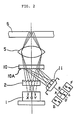
- a laser diode 1 a diffraction grating 2, and an object lens 5 is the same as those in the conventional optical pickup.
- a hologram 10 which diffracts return light beams returned from a disk signal surface to the prescribed direction, is placed between the diffraction grating 2 and the object lens 5.
- a 6-piece-divided photodetector 11 is placed in the direction of the light diffraction by the hologram 10.
- the 6-piece-divided photodetector 11 comprises 4-piece-divided photosensor having four photosensors A, B, C, and D, and a 2-piece-divided photosensor having photosensors E and F disposed at the outsides as shown in Fig. 2, which is the same constitution as the conventional one.
- One surface 10A of the hologram 10 is divided into two areas of 10a and 10b with different grating pitches from each other as shown in Fig. 4.
- the two areas 10a and 10b have such respective grating patterns that lst diffraction light beams from these gratings are focused on P1 and P2 on 4-piece-divided photosensor, respectively.
- a boundary line l between these areas is in the direction perpendicular to the paper surface in Fig. 2.
- the boundary line l and a dividing line m in the 6-piece-divided photodetector 11 are parallel to each other.
- a distance between the hologram 10 and the laser diode 1 is equal to that between the hologram 10 and the 6-piece-divided photodetector (in both cases, center to center distance).
- the three light beams split by the diffraction grating 2 are expressed as three light beams emitted from an actual light source 0 and virtual light sources X and Y. That is, a light path from the actual light source represents a 0th light beam through the diffraction grating 2, and light paths from the virtual light sources X and Y represent lst diffraction light beams.
- a light beam emitted from the laser diode 1 is split by the diffraction grating 2 into three light beams, and split three light beams transmit the hologram 10, are focused by the object lens 5, and form on the signal surface three respective light spots consisting of one main spot and two sub-spots.
- the return light beams reflected from the disk signal surface pass the object lens 5 and are made incident on the hologram 10, along the same paths as those before reaching the signal surface.
- the return light beams are diffracted by the hologram 10.
- the lst diffraction light beams from the hologram 10 go toward the 6-piece-divided photodetector 11 and form light spots on the 6-piece-divided photodetector 11.
- the return light beam from the main spot irradiates photosensors A, B, C and D of the 4-piece-divided photosensor. And the return light beams from the sub-spots irradiate photosensors E and F of the 2-piece-divided photosensor.
- Each return light beam forms two spots corresponding to two areas 10a and 10b of the hologram 10 (top and bottom spots such as P1 and P2 in Fig. 3).
- the light spots on the 6-piece-divided photodetector 11 become like those shown in Fig. 3(a).
- the optical pickup is too near to the disk signal surface and too far from that, the light spots become like those shown in Fig. 3(b) and Fig.
- a foregoing focusing-error detection method is, in a word, a double-knife-edge method, and a tracking-error detection method, a three beams method.
- the four optical devices of the beam splitter 3, the collimator lens 4, the plano-concave lens 7, and the cylindrical lens 8 in the conventional optical pickup are replaced by the one hologram 10 in the invention, the number of included parts has been greatly reduced with the invention. Therefore, the cost can be reduced, the miniaturization of system can be easily attained, and the number of adjusting processes can be reduced because of the decrease of the adjusting points. Moreover, the "playability", that is, the capability to correctly read out signals recorded on the disk, of the pickup of the invention is at least the same as the conventional optical pickup.
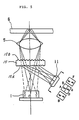
- a laser diode 1 and an object lens 5 is the same as the conventional optical pickup shown in Fig. 1.
- the reference numeral 15 indicates a hologram of the invention.
- the hologram 15 is disposed between the laser diode 1 and the object lens 5, and a 6-piece-divided photodetector 11 is disposed in the direction of the lst diffraction light beams of return light beams from a disk signal surface, which are diffracted by the hologram 15.
- the 6-piece-divided photodetector 11 comprises 4-piece-divided photosensor having four photosensors A, B, C, and D, and a 2-piece-divided photosensor having photosensors E and F disposed at the outsides as shown in Fig. 3, which is the same constitution as the conventional one.
- One surface of the hologram 15 facing the laser diode 1 is made to be a hologram surface 15A, and the hologram surface 15A is divided into two areas 15a and 15b with different grating pitches from each other as shown in Fig. 4.
- the two areas 15a and 15b have such respective grating patterns that the lst diffraction beams from these gratings are focused on P1 and P2 on 4-piece-divided photosensor, respectively (refer to Fig. 3).
- a boundary line l between these areas is in the direction perpendicular to the paper surface in Fig. 5.
- the boundary line l and a dividing line m in the 6-piece-divided photodetector 11 are parallel to each other.
- the other surface of the hologram 15 facing the object lens 5 has a parallel linear grating with a uniform pitch, and is made to be a mere diffraction grating surface 15B for splitting a laser light beam into three light beams through diffraction. Moreover, a distance between the hologram 15 and the laser diode 1 is equal to that between the hologram 15 and the 6-piece-divided photodetector 11 (in both cases, center to center distance).
- the three light beams split by the diffraction grating surface 15B of the hologram 15 are expressed as three light beams emitted from an actual light source 0 and virtual light sources X and Y.
- a light path from the actual light source represents a 0th light beam through the diffraction grating surface 15B
- light paths from the virtual light sources X and Y represent 1st diffraction light beams by the diffraction grating surface 15B.
- the laser light beam emitted from the laser diode 1 is split by the diffraction grating surface 15B of the hologram 15 into the three light beams when passing through the hologram 15, and the split three beams are focused by the object lens 5 so as to form three respective light spots consisting of one main spot and two sub-spots on the signal surface of the optical disk 6.
- the return light beams reflected from the disk signal surface pass the object lens 5, are again made incident on the hologram 15, along the same paths as those before reaching the signal surface, and are diffracted by the hologram surface 15A of the hologram 15.
- First diffraction light beams of the return light beams diffracted by the hologram surface 15A go toward the 6-piece-divided photodetector 11, and form light spots on the 6-piece-divided photodetector 11.
- the return light beam from the main spot irradiates photosensors A, B, C and D of the 4-piece-divided photosensor.
- the return light beams from the sub-spots irradiate photosensors E and F of the 2-piece-divided photosensor.
- Each return light beam forms two spots corresponding to two areas 15a and 15b of the hologram 15 (top and bottom spots such as P1 and P2 in Fig. 3).
- a foregoing focusing-error detection method is, in a word, a double-knife-edge method, and a tracking-error detection method, a three beams method.
- the hologram 15 is a very useful optical device having, in one piece of plate, the function of the diffraction grating for splitting the laser light beam into the three light beams and the function for diffracting the light beams in such a manner that each lst diffraction light beam is focused on two different points.
- the hologram surface 15A and the diffraction grating surface 15B of the hologram 15 diffract both of incident and return light beams.
- the hologram of the above embodiment utilizes the diffracting operation of the diffraction grating surface 15B for the incident light beams, and that of the hologram surface for the return light beams.
- the five optical devices of the diffraction grating 2, the collimator lens 4, the beam splitter 3, the plano-concave lens 7, and the cylindrical lens 8 in the conventional optical pickup are replaced by the one hologram 15.
- the hologram of the invention can also be used for an optical system other than the optical pickup of the foregoing embodiment, which needs the above-described functions of the diffraction grating surface and the hologram surface.
Landscapes
- Physics & Mathematics (AREA)
- Optics & Photonics (AREA)
- General Physics & Mathematics (AREA)
- Optical Head (AREA)
- Optical Recording Or Reproduction (AREA)
Applications Claiming Priority (4)
| Application Number | Priority Date | Filing Date | Title |
|---|---|---|---|
| JP243489/87 | 1987-09-28 | ||
| JP62243489A JPS6486332A (en) | 1987-09-28 | 1987-09-28 | Optical pickup |
| JP243488/87 | 1987-09-28 | ||
| JP62243488A JP2701849B2 (ja) | 1987-09-28 | 1987-09-28 | 光ピックアップ装置 |
Publications (3)
| Publication Number | Publication Date |
|---|---|
| EP0309689A2 true EP0309689A2 (fr) | 1989-04-05 |
| EP0309689A3 EP0309689A3 (en) | 1990-11-22 |
| EP0309689B1 EP0309689B1 (fr) | 1993-10-27 |
Family
ID=26536281
Family Applications (1)
| Application Number | Title | Priority Date | Filing Date |
|---|---|---|---|
| EP88112739A Expired - Lifetime EP0309689B1 (fr) | 1987-09-28 | 1988-08-04 | Tête de lecture optique et séparateur de faisceau holographique associé |
Country Status (3)
| Country | Link |
|---|---|
| US (2) | US4907847A (fr) |
| EP (1) | EP0309689B1 (fr) |
| DE (1) | DE3885224T2 (fr) |
Cited By (7)
| Publication number | Priority date | Publication date | Assignee | Title |
|---|---|---|---|---|
| EP0374841A1 (fr) * | 1988-12-20 | 1990-06-27 | Nec Corporation | Dispositif avec tête optique pour la détection optimale d'une erreur de focus |
| EP0380320A3 (fr) * | 1989-01-27 | 1991-06-26 | Sharp Kabushiki Kaisha | Dispositif de tête optique |
| EP0426053A3 (en) * | 1989-10-30 | 1991-12-18 | Nippon Conlux Co., Ltd. | Optical head for optical information recording medium |
| EP0402123A3 (fr) * | 1989-06-06 | 1992-03-04 | Sharp Kabushiki Kaisha | Dispositif de tête optique |
| EP0580936A1 (fr) * | 1992-07-27 | 1994-02-02 | Matsushita Electronics Corporation | Elément à diffraction et ensemble de tète de lecture optique |
| EP0612064A3 (fr) * | 1988-06-23 | 1995-08-30 | Sharp Kk | Appareil de reproduction optique. |
| EP1351227A4 (fr) * | 2001-01-12 | 2005-02-09 | Sony Corp | Capteur optique et unite de disque optique |
Families Citing this family (24)
| Publication number | Priority date | Publication date | Assignee | Title |
|---|---|---|---|---|
| JPH06103543B2 (ja) * | 1988-12-31 | 1994-12-14 | 三星電子株式会社 | レーザピックアップ |
| KR920704159A (ko) * | 1989-08-21 | 1992-12-19 | 알. 아모스 칼 | 전자현상 조작방법 및 장치 |
| JPH03174103A (ja) * | 1989-09-19 | 1991-07-29 | Fujitsu Ltd | 色消しホログラム光学系 |
| US5212375A (en) * | 1990-10-09 | 1993-05-18 | Olympus Optical Co., Ltd. | Camera focus detection system using holographic beam splitter |
| US5471344A (en) * | 1991-03-29 | 1995-11-28 | Canon Kabushiki Kaisha | Photographing apparatus having optical low-pass filter |
| KR950001073B1 (ko) * | 1991-09-19 | 1995-02-08 | 삼성전자 주식회사 | 홀로그램(Hologram) 소자를 이용한 광 픽업 장치 |
| US5272550A (en) * | 1991-10-11 | 1993-12-21 | International Business Machines Corporation | Hologram system |
| CA2079620A1 (fr) * | 1991-10-25 | 1993-04-26 | Roeland M. T. Hekker | Elements holographiques pour systeme d'enregistrement optique |
| KR970008231B1 (en) * | 1992-06-03 | 1997-05-22 | Lg Electronics Inc | Optical pick-up apparatus |
| KR950005957B1 (ko) * | 1992-06-04 | 1995-06-07 | 주식회사금성사 | 광 픽업 시스템 |
| KR950005033B1 (ko) * | 1992-11-06 | 1995-05-17 | 주식회사금성사 | 광픽업 장치 |
| US6072607A (en) * | 1993-10-15 | 2000-06-06 | Sanyo Electric Co., Ltd. | Optical pickup device |
| US5548418A (en) * | 1994-01-14 | 1996-08-20 | Dcs Corporation | Holographic structured light generator |
| US5471046A (en) * | 1994-02-25 | 1995-11-28 | Eastman Kodak Company | Camera auto-focusing system with designator using a volume holographic element |
| US5569904A (en) * | 1994-07-19 | 1996-10-29 | Eastman Kodak Company | Multispot autofocus system having a radiation emitter which emits radiation that is divided into a plurality of discrete beams |
| JP3660415B2 (ja) * | 1995-02-07 | 2005-06-15 | 富士通株式会社 | 光学記憶装置用光学デバイス |
| JPH10172170A (ja) * | 1996-10-09 | 1998-06-26 | Sanyo Electric Co Ltd | 光ピックアップ装置およびその製造方法 |
| EP0851414A3 (fr) * | 1996-12-26 | 2000-09-27 | Sanyo Electric Co. Ltd | Tête de lecture optique et lecteur de supports d'enregistrement |
| JP3362768B2 (ja) * | 1998-02-19 | 2003-01-07 | 株式会社ケンウッド | 光ピックアップ装置 |
| JP3691274B2 (ja) * | 1999-02-10 | 2005-09-07 | ローム株式会社 | 光ピックアップおよびホログラム素子 |
| DE19936007A1 (de) | 1999-08-04 | 2001-02-15 | Thomson Brandt Gmbh | Gerät zum Lesen und/oder Beschreiben optischer Aufzeichnungsträger |
| US6935006B2 (en) * | 2002-12-18 | 2005-08-30 | Honeywell International, Inc. | Spun metal form used to manufacture dual alloy turbine wheel |
| GB0408383D0 (en) * | 2004-04-15 | 2004-05-19 | Koninkl Philips Electronics Nv | A radio network and a method of operating a radio network |
| US11480793B2 (en) * | 2018-10-24 | 2022-10-25 | Google Llc | Systems, devices, and methods for aligning a lens in a laser projector |
Family Cites Families (7)
| Publication number | Priority date | Publication date | Assignee | Title |
|---|---|---|---|---|
| BE755782A (fr) * | 1969-09-05 | 1971-03-04 | Philips Nv | Filtre multiplex optique |
| US3767310A (en) * | 1972-06-23 | 1973-10-23 | Ibm | Diffraction grating beam splitter |
| JPH0627907B2 (ja) * | 1983-02-16 | 1994-04-13 | 株式会社日立製作所 | 光学的情報処理装置 |
| US4497534A (en) * | 1983-02-28 | 1985-02-05 | International Business Machines Corporation | Holographic optical head |
| EP0228620B1 (fr) * | 1985-12-10 | 1991-06-05 | Nec Corporation | Tête optique avec réseau de diffraction pour diriger deux ou plusieurs faisceaux lumineux diffractés sur des détecteurs optiques |
| NL8701749A (nl) * | 1987-07-24 | 1989-02-16 | Philips Nv | Inrichting voor het met optische straling aftasten van een informatievlak. |
| DE3855936T2 (de) * | 1987-08-24 | 1998-01-02 | Sharp Kk | Optische Abtastvorrichtung |
-
1988
- 1988-08-02 US US07/227,330 patent/US4907847A/en not_active Expired - Lifetime
- 1988-08-04 EP EP88112739A patent/EP0309689B1/fr not_active Expired - Lifetime
- 1988-08-04 DE DE88112739T patent/DE3885224T2/de not_active Expired - Lifetime
-
1990
- 1990-01-02 US US07/446,820 patent/US5016954A/en not_active Expired - Lifetime
Cited By (12)
| Publication number | Priority date | Publication date | Assignee | Title |
|---|---|---|---|---|
| EP0612064A3 (fr) * | 1988-06-23 | 1995-08-30 | Sharp Kk | Appareil de reproduction optique. |
| EP0374841A1 (fr) * | 1988-12-20 | 1990-06-27 | Nec Corporation | Dispositif avec tête optique pour la détection optimale d'une erreur de focus |
| EP0380320A3 (fr) * | 1989-01-27 | 1991-06-26 | Sharp Kabushiki Kaisha | Dispositif de tête optique |
| US5410529A (en) * | 1989-01-27 | 1995-04-25 | Sharp Kabushiki Kaisha | Optical pickup apparatus |
| EP0402123A3 (fr) * | 1989-06-06 | 1992-03-04 | Sharp Kabushiki Kaisha | Dispositif de tête optique |
| US5253237A (en) * | 1989-06-06 | 1993-10-12 | Sharp Kabushiki Kaisha | Optical head device |
| EP0426053A3 (en) * | 1989-10-30 | 1991-12-18 | Nippon Conlux Co., Ltd. | Optical head for optical information recording medium |
| AU640176B2 (en) * | 1989-10-30 | 1993-08-19 | Nippon Conlux Co., Ltd. | Optical head for optical information recording medium |
| EP0580936A1 (fr) * | 1992-07-27 | 1994-02-02 | Matsushita Electronics Corporation | Elément à diffraction et ensemble de tète de lecture optique |
| US5481524A (en) * | 1992-07-27 | 1996-01-02 | Matsushita Electronics Company | Diffraction element and optical pick-up assembly |
| EP1351227A4 (fr) * | 2001-01-12 | 2005-02-09 | Sony Corp | Capteur optique et unite de disque optique |
| US6987614B2 (en) | 2001-01-12 | 2006-01-17 | Sony Corporation | Optical pickup and optical disc drive device |
Also Published As
| Publication number | Publication date |
|---|---|
| DE3885224D1 (de) | 1993-12-02 |
| DE3885224T2 (de) | 1994-05-05 |
| US5016954A (en) | 1991-05-21 |
| EP0309689B1 (fr) | 1993-10-27 |
| US4907847A (en) | 1990-03-13 |
| EP0309689A3 (en) | 1990-11-22 |
Similar Documents
| Publication | Publication Date | Title |
|---|---|---|
| US5016954A (en) | Optical pickup and hologram therefor | |
| US5065380A (en) | Diffraction grating for an optical pickup device | |
| EP0378438B1 (fr) | Dispositif de tête optique | |
| EP0354019B1 (fr) | Dispositif de tête optique pour la lecture d'information emmagasinée dans un milieu d'enregistrement | |
| EP0338840B1 (fr) | Appareil optique pour la reproduction | |
| EP0426879B1 (fr) | Appareil d'enregistrement et/ou reproduction optique | |
| EP0075676B1 (fr) | Appareil optique de localisation de piste et dispositif á disque optique utilisant un tel appareil | |
| USRE35332E (en) | Optical pickup device with diffraction device | |
| US5608695A (en) | Optical pick-up apparatus with tracking error detection by detection of amount of light in fan field | |
| EP0402123A3 (fr) | Dispositif de tête optique | |
| EP0612064B1 (fr) | Appareil de reproduction optique | |
| CN1073258C (zh) | 对于表面进行光学扫描用的装置 | |
| EP0311463A2 (fr) | Appareil pour la reproduction optique d'information | |
| JP2701849B2 (ja) | 光ピックアップ装置 | |
| US5001334A (en) | Photodetector for hologram-type optical head including means for detecting return light spot deviation | |
| JPH06274904A (ja) | 光ピックアップ装置 | |
| KR910020667A (ko) | 광헤드장치 | |
| US6466526B1 (en) | Apparatus for recording and replaying information on optical information record medium and optical pickup | |
| JP2594445B2 (ja) | ホログラム光ヘッド | |
| JPS6486332A (en) | Optical pickup | |
| EP0628955B1 (fr) | Tête optique | |
| KR200172921Y1 (ko) | 홀로그램소자를 채용한 광픽업 장치 | |
| JP2734685B2 (ja) | 光検出器の調整方法および焦点誤差検出装置 | |
| KR100224896B1 (ko) | 광이용 효율을 높인 광 픽업 장치 | |
| EP0845776A1 (fr) | Système et méthode de discrimination de position d'un tache lumineuse |
Legal Events
| Date | Code | Title | Description |
|---|---|---|---|
| PUAI | Public reference made under article 153(3) epc to a published international application that has entered the european phase |
Free format text: ORIGINAL CODE: 0009012 |
|
| AK | Designated contracting states |
Kind code of ref document: A2 Designated state(s): DE FR GB |
|
| RHK1 | Main classification (correction) |
Ipc: G11B 7/09 |
|
| PUAL | Search report despatched |
Free format text: ORIGINAL CODE: 0009013 |
|
| AK | Designated contracting states |
Kind code of ref document: A3 Designated state(s): DE FR GB |
|
| 17P | Request for examination filed |
Effective date: 19910429 |
|
| 17Q | First examination report despatched |
Effective date: 19920629 |
|
| GRAA | (expected) grant |
Free format text: ORIGINAL CODE: 0009210 |
|
| STAA | Information on the status of an ep patent application or granted ep patent |
Free format text: STATUS: THE PATENT HAS BEEN GRANTED |
|
| AK | Designated contracting states |
Kind code of ref document: B1 Designated state(s): DE FR GB |
|
| REF | Corresponds to: |
Ref document number: 3885224 Country of ref document: DE Date of ref document: 19931202 |
|
| ET | Fr: translation filed | ||
| PLBI | Opposition filed |
Free format text: ORIGINAL CODE: 0009260 |
|
| 26 | Opposition filed |
Opponent name: N.V. PHILIPS' GLOEILAMPENFABRIEKEN Effective date: 19940421 |
|
| PLAW | Interlocutory decision in opposition |
Free format text: ORIGINAL CODE: EPIDOS IDOP |
|
| APAC | Appeal dossier modified |
Free format text: ORIGINAL CODE: EPIDOS NOAPO |
|
| APAE | Appeal reference modified |
Free format text: ORIGINAL CODE: EPIDOS REFNO |
|
| REG | Reference to a national code |
Ref country code: GB Ref legal event code: 732E |
|
| RAP2 | Party data changed (patent owner data changed or rights of a patent transferred) |
Owner name: NEC CORPORATION |
|
| APAC | Appeal dossier modified |
Free format text: ORIGINAL CODE: EPIDOS NOAPO |
|
| REG | Reference to a national code |
Ref country code: FR Ref legal event code: TP |
|
| REG | Reference to a national code |
Ref country code: GB Ref legal event code: IF02 |
|
| APBU | Appeal procedure closed |
Free format text: ORIGINAL CODE: EPIDOSNNOA9O |
|
| PLBQ | Unpublished change to opponent data |
Free format text: ORIGINAL CODE: EPIDOS OPPO |
|
| PLAB | Opposition data, opponent's data or that of the opponent's representative modified |
Free format text: ORIGINAL CODE: 0009299OPPO |
|
| R26 | Opposition filed (corrected) |
Opponent name: KONINKLIJKE PHILIPS ELECTRONICS N.V. Effective date: 19940421 |
|
| APAH | Appeal reference modified |
Free format text: ORIGINAL CODE: EPIDOSCREFNO |
|
| PGFP | Annual fee paid to national office [announced via postgrant information from national office to epo] |
Ref country code: DE Payment date: 20070802 Year of fee payment: 20 |
|
| PGFP | Annual fee paid to national office [announced via postgrant information from national office to epo] |
Ref country code: GB Payment date: 20070801 Year of fee payment: 20 |
|
| PGFP | Annual fee paid to national office [announced via postgrant information from national office to epo] |
Ref country code: FR Payment date: 20070808 Year of fee payment: 20 |
|
| REG | Reference to a national code |
Ref country code: GB Ref legal event code: PE20 Expiry date: 20080803 |
|
| PG25 | Lapsed in a contracting state [announced via postgrant information from national office to epo] |
Ref country code: GB Free format text: LAPSE BECAUSE OF EXPIRATION OF PROTECTION Effective date: 20080803 |
|
| PLAB | Opposition data, opponent's data or that of the opponent's representative modified |
Free format text: ORIGINAL CODE: 0009299OPPO |
|
| R26 | Opposition filed (corrected) |
Opponent name: KONINKLIJKE PHILIPS N.V. Effective date: 19940421 |
|
| PLAB | Opposition data, opponent's data or that of the opponent's representative modified |
Free format text: ORIGINAL CODE: 0009299OPPO |
|
| R26 | Opposition filed (corrected) |
Opponent name: KONINKLIJKE PHILIPS N.V. Effective date: 19940421 |
|
| PLAB | Opposition data, opponent's data or that of the opponent's representative modified |
Free format text: ORIGINAL CODE: 0009299OPPO |
|
| R26 | Opposition filed (corrected) |
Opponent name: KONINKLIJKE PHILIPS N.V. Effective date: 19940421 |