EP0309760A2 - Tracteur de piste pour avion à force d'arrimage définie - Google Patents
Tracteur de piste pour avion à force d'arrimage définie Download PDFInfo
- Publication number
- EP0309760A2 EP0309760A2 EP88114319A EP88114319A EP0309760A2 EP 0309760 A2 EP0309760 A2 EP 0309760A2 EP 88114319 A EP88114319 A EP 88114319A EP 88114319 A EP88114319 A EP 88114319A EP 0309760 A2 EP0309760 A2 EP 0309760A2
- Authority
- EP
- European Patent Office
- Prior art keywords
- lifting
- nose wheel
- clamping
- hold
- towing vehicle
- Prior art date
- Legal status (The legal status is an assumption and is not a legal conclusion. Google has not performed a legal analysis and makes no representation as to the accuracy of the status listed.)
- Granted
Links
Images


Classifications
-
- B—PERFORMING OPERATIONS; TRANSPORTING
- B64—AIRCRAFT; AVIATION; COSMONAUTICS
- B64F—GROUND OR AIRCRAFT-CARRIER-DECK INSTALLATIONS SPECIALLY ADAPTED FOR USE IN CONNECTION WITH AIRCRAFT; DESIGNING, MANUFACTURING, ASSEMBLING, CLEANING, MAINTAINING OR REPAIRING AIRCRAFT, NOT OTHERWISE PROVIDED FOR; HANDLING, TRANSPORTING, TESTING OR INSPECTING AIRCRAFT COMPONENTS, NOT OTHERWISE PROVIDED FOR
- B64F1/00—Ground or aircraft-carrier-deck installations
- B64F1/22—Ground or aircraft-carrier-deck installations for handling aircraft
- B64F1/223—Ground or aircraft-carrier-deck installations for handling aircraft for towing aircraft
- B64F1/225—Vehicles specially adapted therefor, e.g. aircraft tow tractors
- B64F1/227—Vehicles specially adapted therefor, e.g. aircraft tow tractors for direct connection to aircraft, e.g. tow tractors without towing bars
-
- B—PERFORMING OPERATIONS; TRANSPORTING
- B64—AIRCRAFT; AVIATION; COSMONAUTICS
- B64F—GROUND OR AIRCRAFT-CARRIER-DECK INSTALLATIONS SPECIALLY ADAPTED FOR USE IN CONNECTION WITH AIRCRAFT; DESIGNING, MANUFACTURING, ASSEMBLING, CLEANING, MAINTAINING OR REPAIRING AIRCRAFT, NOT OTHERWISE PROVIDED FOR; HANDLING, TRANSPORTING, TESTING OR INSPECTING AIRCRAFT COMPONENTS, NOT OTHERWISE PROVIDED FOR
- B64F1/00—Ground or aircraft-carrier-deck installations
- B64F1/22—Ground or aircraft-carrier-deck installations for handling aircraft
Definitions
- the invention relates to a towing vehicle for aircraft of the type specified in the preamble of claim 1.
- the hold-down devices are horizontal brackets which have to be adjusted to a position adapted to the nose wheel diameter before the nose wheel is picked up, so that the nose wheel with its apex against it at the end of its picking up process the hold-down comes to the system.
- the lifting bucket is mechanically blocked in the position reached at the end of the lifting process.
- the lifting and clamping device in the known towing vehicle has the disadvantage that the nose wheel is fixed on the towing vehicle exclusively by at the nose wheel circumference, in a rigid position specified elements takes place, and the clamped nose wheel is not subject to positive clamping forces.
- This only positive, but not non-positive fixing of the nose wheel has the consequence that strong towing movements of the nose wheel within the clamping can take place during towing and especially when starting due to the pitching moments exerted by the aircraft on the nose wheel, since the flexibility of the air-filled nose wheel tire leaves a certain freedom of movement allows.
- the invention has for its object to improve the clamping of the nose wheel on the tractor in such a way that in particular dynamic loads on the nose wheel do not lead to excessive intrinsic movements of the nose wheel within the clamping and in no case to free the nose wheel in a towing vehicle of the type mentioned.
- the solution to the problem is specified in claim 1.
- the nose wheel is not only clamped in a form-fitting manner, but also in a force-fitting manner.
- the clamping force can be set to a predetermined value that is the same for all of the wheel types and diameters in question.
- the subclaims indicate further advantageous refinements of the invention.
- the advantage is achieved that the loading of the lifting blade with the predetermined Clamping force at the end of the recording process can be done by simply switching on an additional hydraulic pressure without a special control system with sensors for the current actual pressure or the current actual position being required.
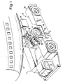
- FIG. 1 schematically shows a towing vehicle 1 when towing a commercial aircraft 2.
- the towing vehicle 1 has a fork-shaped chassis with two side legs 1a, 1b, which delimit a chassis recess 3 which is open to the rear between them.
- the towing vehicle is maneuvered backwards against the aircraft to be towed such that the nose gear of the aircraft enters the recess 3.
- the nose wheels 4 of the aircraft are gripped by a lifting and clamping device, lifted and clamped to the towing vehicle 1 in a force-locking manner.
- the lifting and clamping device which is only shown in simplified form in FIG.
- An abutment or luffing jig 6 pivotably mounted on the vehicle about an axis 5 running in the longitudinal direction thereof, which has a rearward-facing, approximately vertical stop surface 7 for the nose wheels 4;
- a ramp 10 mounted tiltably on the luffing jib 6 about a horizontal axis, which supports the nose wheels 4 from below;
- Two hold-down devices 20 movably mounted on the luffing jib 6, each of which rests against a nose wheel 4 from the front and above and can be pressed against the nose wheel by means of a hydraulic tensioning device; -
- Fig. 1 it can also be seen that 4 other devices belonging to the nose gear, such as the hydraulic steering cylinders 8 and the bottom flap 9 of the nose gear shaft, can be located directly above the upper edge of the nose wheels. It is an essential requirement that the lifting and clamping device must be designed in such a way that even in the event of a malfunction or incorrect operation, any damage to these parts belonging to the aircraft must be excluded.
- FIG. 2 shows a side view of the half of the lifting device associated with the right side leg 1b of the vehicle.
- Fig. 3 shows a plan view of the entire lifting and clamping device.
- the seesaw 6 with the stop surface 7 is pivotally mounted on a cross member 1c of the vehicle about its longitudinal axis by means of the pivot axis 5.
- the ramp 10 is mounted such that it can be tilted about the horizontal axis 11.
- the ramp 10 is scoop-shaped with an upwardly concave or angled profile, so that its front part (lying to the left of the axis 11 in FIG. 2) is inclined more steeply than the rear part, and it can carry a centering rib 12 in its center. which engages between the two nose wheels 4 of the nose landing gear to center it with respect to the center of the vehicle.
- the ramp 10 in FIG. 2 shows the ramp 10 in its rest position, in which its lower surface runs approximately parallel to the road 13 and the ramp 10 does not also protrude below the floor surface of the towing vehicle, that is to say does not impair its ground clearance. From this normal position, the ramp 10 in FIG. 2 can be tilted clockwise downward until it reaches a receiving position in which its rear edge is only a short distance from the roadway 13 around the nose wheels to record. When the nose wheels are picked up, the ramp 10 then tilts counterclockwise in FIG. 2 back into the rest position shown and furthermore into a support position in which it supports the nose gear taken up.
- Each hold-down device 20 carries a roller 21 at its end and is supported on both sides by means of two parallel links 22 on a hold-down bracket 24, which in turn is mounted on a forward-projecting bracket 6a of the luffing bracket 6 by means of two links 27.
- a hydraulic hold-down cylinder 28 pivotably mounted on the chassis acts on the hold-down support 24 in order to exert a hold-down force directed downward.
- the hold-down bracket 24 has in its upper part a contact surface 26 which limits the pivoting path of the hold-down device 20 guided on the links 22. The arrangement is such that the hold-down 20 from the rearmost position shown in Fig.
- the Boeing 757 aircraft model has the smallest nose wheel diameter of 31 inches (79 cm) and the 747 aircraft model has the largest nose wheel diameter of 49 inches (124 cm), while the nose wheel diameters of other common commercial aircraft such as Boeing 767, DC 8 and DC 10 and Airbus A 300 and A 310 lie between these extremes.
- the roller 21 In the lowest position shown in FIG. 2, the roller 21 is at a distance from the road 13 which is smaller than the smallest nose wheel diameter and larger than half the largest nose wheel diameter of the types mentioned, that is between 62 and 79 cm.
- the hold-down device also projects so far to the rear that it is located approximately above the receiving edge of the ramp 10, but in any case behind its tilting axis 11.
- the hold-down device 20 comes to rest on a nose wheel to be picked up, regardless of its diameter, in the front upper quadrant of the circumference at the beginning of the picking process, and then taken up by the nose wheel when it ascends onto the ramp 10, whereby it cannot at any time before or during the recording process be in a position higher than the upper edge of a nose wheel, where it or devices belonging to the nose landing gear, such as steering cylinders, floor flaps or . Like. could damage.
- the lifting blades 40 lie opposite the complex of stop surface 7, drive-on ramp 10 and hold-downs 20. These are each designed as a roller block, with an upper rigid and a lower movable part, as will be explained below.
- Each lifting vane 40 is pivotally mounted on a rocker 42 about an approximately vertical axis 41, which is mounted in a horizontal-axis pivot bearing 43 on the corresponding side leg, for example 1b of the vehicle and by means of a lifting cylinder 44 from the rear position shown in FIG. 2 to the front in Direction against the ramp 10 and the abutment 7 can be moved to push a nose wheel onto the ramp 10.
- Each lifting blade 40 is also mounted on the rocker arm 42 so that it can be tilted about an axis 45, and while the lifting cylinder 44 moves the rocker arm 42 forward with the lifting blade 40, the tilting tendency of the lifting blade 40 is controlled by means of a steering linkage consisting of a control arm 46, a Coupling link 47 and two links 48, 49, the upper end of which is on the coupling link 47 connected and the lower end of which is mounted in bearings 48a, 49a on the side leg 1b of the vehicle.
- a steering linkage consisting of a control arm 46, a Coupling link 47 and two links 48, 49, the upper end of which is on the coupling link 47 connected and the lower end of which is mounted in bearings 48a, 49a on the side leg 1b of the vehicle.
- the rear articulation point 46a of the control arm 46 is guided on an arcuate path B which is initially directed downward and then rises again, particularly in its front rising section, when the lifting blade 40 moves forward is steeper than an arc.
- the lifting blade 40 can be pivoted about the axis 41 in a rest position resting on the side wall of the side leg 1b of the chassis, as shown in FIG. 3 for the lifting blade 40 of the side leg 1a on the left in the direction of travel is.
- both lifting blades When approaching a nose landing gear, both lifting blades must of course be pivoted into the rest position so that the nose landing gear can enter the recess 3 of the chassis. The lifting blades are then swung into the working position behind the nose wheels to reach behind the nose wheels.
- the mounting and the drives for the lifting blades 40 are shown in detail in FIG. 4.
- the swing arm 42 which can be pivoted about a horizontal axis on the vehicle in the pivot bearing 43 carries a bearing sleeve 52, in which a shaft journal 53 of a lifting vane carrier 54 is rotatably mounted about the axis 41.
- the lifting vane carrier 54 in turn forms a horizontal-axis bearing for supporting a shaft 45, on which the lifting vane 40 is arranged in a rotationally fixed manner by means of a toothing 45a.
- the bearing for the shaft 45 formed by the lifting vane carrier 54 is closed to 360 ° only in the area facing the lifting vane 40 and then has a cutout 54a open to the rear, through which the fork-shaped end 45b of the shaft can be seen in FIG 45 sees.
- a bearing eye 46b formed on the control arm 46 engages in this and is connected to the shaft 45 in an articulated manner by means of a hinge pin 55, the hinge axis running coaxially to the pivot axis 41.
- the control arm 46 is rotatably connected to the shaft 45 with respect to its axis and can control its rotation relative to the lifting vane carrier 54 when the lifting cylinder 44 pivots the rocker 42 and thus the lifting vane 40 about the axis of the pivot bearing 43 to the front.
- the articulated connection of the control arm 46 with the shaft 45 enables the lifting vane carrier 54 with the lifting vane 40 to be pivoted about the axis 41 of the bearing sleeve 52, so that the lifting vane 40 can assume its rest position indicated by the dot-dash line at 40 '.
- This pivoting is effected by the hydraulic rotary motor 57, which is attached to the rocker 42 and drives a crank arm 58, which is connected at its free end via a joint 58a to a coupling link 59, which in turn is mounted in a joint bearing 61 of the lifting vane carrier 54 .
- crank arm 58 bears against a fixed stop 42a of the rocker 42, which prevents a further rotation of the crank arm 58 in the clockwise direction in FIG. 4. Since in this position the longitudinal axis of the coupling link 59 lies between the joints 58a and 61 on the right-hand side of the axis of the rotary motor 57 in FIG. 4, the rearward reaction forces on the crank arm which act on the lifting blade 40 when a nose wheel is picked up and clamped in place 58, a torque directed clockwise from FIG. 4, which is received by the stop 42a. The lifting blade 40 is thus mechanically locked in its working position.
- the hydraulic rotary motor 57 In order to move the lifting blade 40 into its rest position, the hydraulic rotary motor 57 must be operated in this way 4, which rotates the crank arm 58 counterclockwise from Fig. 4, which moves away from the stop 42a and the longitudinal axis of the coupling link 59 passes through the dead center under the axis of the rotary motor 57.
- a pivoting path of the crank arm 58 of more than 180 ° is required for the pivoting of the lifting vane carrier 54 through 90 ° about the axis 41 in order to bring the lifting vane 40 into the rest position, with the joint 58a at the end of this pivoting movement free end of the crank arm is approximately in the position in which the articulated bearing 61 of the lifting blade carrier 54 is located in FIG. 4.
- the lifting blade Since the pivot axis 41 is not exactly perpendicular, but rather is inclined slightly to the front, the lifting blade is raised somewhat when it is pivoted into the rest position, so that its lower edge does not impair the ground clearance of the towing vehicle. In the working position before and during the recording process, on the other hand, it is harmless if the lifting bucket protrudes downward over the lower edge of the vehicle.
- FIG. 5 schematically illustrates various positions of the lifting and clamping device when picking up a nose wheel.
- the size relationships shown relate to a nose wheel, the diameter of which lies at the lower limit of the area of the nose wheel diameter of the usual commercial aircraft for which the towing vehicle is designed. As already mentioned, this range extends from approx. 30 inches (75 cm) to approx. 50 inches (approx. 125 cm) and therefore covers aircraft of the type Boeing 757 (nose wheel diameter 31 inches) at its lower limit and aircraft at its upper limit type Boeing 747 (nose wheel diameter 49 inches).
- the lifting and clamping device must be designed so that all nose wheels lying in this diameter range are picked up properly and without risk of damage and are so securely clamped in the picked-up state that they can under no circumstances be released unintentionally.
- the lifting blades 40 are pivoted into the rest position and the towing vehicle is moved backwards towards the aircraft in such a way that the nose wheel enters the U-recess of the chassis and is finally touched by the rear edge of the ramp 10.
- the ramp 10 tilted down to the position 10,, which is shown in Fig. 5 in solid lines.
- the limit switch S2 is actuated, the switching signal of which makes the drive of the towing vehicle ineffective, at least for reverse travel, so that the towing vehicle cannot move further against the nose wheel 4 and could possibly damage it.
- the switching signal S2 activates the drive devices 57, 44 for the lifting bucket 40, so that the driver of the towing vehicle can switch on these drives by means of an operating lever.
- the limit switch S2 has not yet been actuated to indicate the correct presence of a nose wheel 4 on the ramp 10
- the lifting bucket drives are deactivated in order to rule out incorrect operation.
- the lifting vane drives are switched on, the respective lifting vane is first pivoted from the rest position into the working position by means of the hydraulic rotary motor 57 and then the lifting cylinder 44 is acted upon with hydraulic medium in order to push out its piston rod.
- the lifting vane 40 and the control arm 46 connected to it at an angle-stiffness from the initial position shown in dashed lines in FIG.
- the hold-down device 20 lies against the circumference of the nose wheel 4 and is moved forward and upward on the curved path A under the guidance of Handlebar 22 entrained, its contact point always lies approximately in the middle of the front upper circumferential quadrant of the nose wheel circumference, that is to say at an angular distance of approximately 30-60 ° from the apex of the nose wheel.
- the hold-down device 20 comes to rest against the contact surface 26 of the hold-down support 24 and takes it up under guidance by the handlebars 27, the piston rod of the hold-down cylinder being pulled out.
- the guidance of the control arm 46 of the lifting blade 40 by the steering gear causes the lifting blade to initially be tilted somewhat backwards when it is pivoted forward, so that its lower part 40a can reach under the nose wheel as deeply as possible. In the last part of the forward movement, however, the lifting blade 40 is tilted strongly forward, so that its upper, rigid part lies completely or approximately against the nose wheel circumference and acts as a lock which, together with the hold-down device 20, prevents the nose wheel from escaping upwards.
- the limit switch S1 When the nose wheel strikes the stop surface 7 and the ramp 10 has reached its upper position, the limit switch S1 is actuated, the switching signal of which causes the lifting cylinder 44 and the Hold-down cylinders 28 (see FIG. 2; not shown in FIG. 5) are each subjected to a predetermined hydraulic pressure in order to press the lifting blade 40 and the hold-down device 20 against the nose wheel circumference with a predetermined clamping force in each case. This ensures that the nose wheel and the like regardless of the tire pressure, the wear or renewal condition of the tire surface. is clamped sufficiently firmly.
- the rod clamp 44a of the lifting cylinder 44 is then released in order to mechanically block the piston rod, and the hydraulic medium under the predetermined holding-down pressure is enclosed in the holding-down cylinder 28. All of these processes take place automatically after the lifting bucket drives are actuated by the driver of the towing vehicle.
- a malfunction occurs while the nose wheel is clamped during transport, e.g. a pressure loss in the tire of a nose wheel
- This pressure drop is detected by the pressure sensor already mentioned and leads to the triggering of a fault or Alarm signal so that, for example, the transport trip can be stopped immediately.
- piston rod clamping 28a of the hold-down cylinder 28 is triggered by the backward movement of the hold-down device, and the piston rod is mechanically blocked after a few mm of forward movement, so that the nose wheel cannot come free from the clamping despite the fault that has occurred.
- FIG. 6 shows, in a representation similar to FIG. 5, the position when receiving a nose wheel, the diameter of which lies at the upper limit of the diameter range in question, in particular the nose wheel of a type B 747 aircraft with a diameter of 49 inches.
- the nose wheel 4 lies against the ramp 10 and has tilted it downwards.
- the hold-down 20 is already in this position on the circumference of the nose wheel.
- the lifting blade 40 comes after a very small forward movement from its starting position to the circumference of the nose wheel, whereby it has not yet been tilted significantly to the rear by the control arm 46.
- the lifting blade 40 is increasingly moved backwards by the control arm 46, ie tilted clockwise of Fig. 6, whereby its lower part 40a increasingly pushes under the nose wheel.
- the hold-down device 20 moves on its path A predetermined by the guide links 22 and then by the guide links 27, as a result of which its contact point on the circumference of the nose wheel 4 shifts only slightly and also in this case always at an angular distance between approximately 30 ° and 60 ° from the apex of the nose wheel.
- the hold-down carrier 24 is moved upwards by a considerably greater distance than is the case with the small nose wheel according to FIG. 5.
- the lifting vane has only reached a position in its clamping position shown at 40 ', which is approximately halfway between positions 40' and 40 'of Fig. 5.
- FIGS. 5 and 6 For the understanding of FIGS. 5 and 6, it should also be noted that, for the sake of simplicity, these have been drawn as if the nose wheel 4 and thus the entire aircraft were being moved forward. In fact, however, the aircraft stands still during the recording process, and by pressing the lifting blade 40 against the nose wheel 4, the entire towing vehicle is moved backwards (In Fig. 5 and 6 to the right), so that the ramp 10 is pushed under the nose wheel and the nose wheel performs a substantially only vertically upward movement. Taking into account the backward movement of the towing vehicle would, however, have resulted in a very confusing graphic representation, which is why the positions in FIGS. 5 and 6 are only shown relative to the stationary towing vehicle.
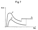
- the lifting blade 40 At the start of a pickup operation, the lifting blade 40 must take up substantially all of the weight bearing on the nose wheel and additionally exert a force for releasing the nose wheel from the ground.
- the lifting cylinder 44 must therefore exert a very high force at the beginning of a recording process and must therefore be subjected to a high pressure.
- an increasing part of the nose wheel load is taken over by the ramp 10, in particular when it tilts about its tilt axis into the upper position.
- the force to be exerted by the lifting blade, and thus also the hydraulic pressure prevailing in the lifting cylinder 44 correspondingly decrease.
- the clamping pressure P e is selected so that the clamping force exerted on the nose wheel cannot lead to damage to the nose wheel or, for example, to a flat pressing of the nose wheel tire against the rim. Tests have shown that the clamping force on the nose wheel corresponding to the clamping pressure P e should be of the order of 2 t.
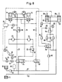
- FIG. 8 shows a simplified electrical and hydraulic circuit diagram of the lifting and clamping device.
- hydraulic lines with thick solid lines hydraulic control pressure lines are dash-dotted and electrical signal lines are shown with dashed lines.
- the lifting cylinders 44 and the rotary motors 57 for the two lifting blades and the hold-down cylinders 28 for the hold-down devices 20 are shown as hydraulically operated devices.
- the hydraulic pressure is supplied into the pressure line 67 from a supply system, comprising a reservoir 60, a pump 63 and, if appropriate, a pressure accumulator 65.
- a leak line 69 leads to a collecting container 71.
- a valve 75 which can be actuated electrically by the driver of the towing vehicle by means of a lever 73, controls the application of hydraulic medium to the rotary motors 57 and lifting cylinders 44.
- the actuation of the valve 75 is only possible if the towing vehicle has approached the nose wheel properly, so that the nose wheel has tilted the ramp 10 downward, thereby actuating the limit switch S2, which releases the valve 75 for actuation via a relay 81. If the valve 75 is brought into the position shown in FIG. 8, hydraulic medium reaches the rotary motors 57 via the line 77. in order to pivot the lifting blades from the rest position through 90 ° into the working position (cf. Fig. 4).
- the hydraulic medium from the rotary motors 57 can flow into the leak line 69 via a check valve 85 and the line 79.
- the pressure prevailing in the rotary motors 57 is less than the opening pressure of a pressure switching valve 83, which blocks the supply of hydraulic medium to the lifting cylinders 44.
- the hydraulic pressure in the line 77 increases, so that the pressure switching valve 83 opens and the piston-side working spaces of the lifting cylinders 44 are acted upon by hydraulic medium are so that their piston rods are extended and the lifting blades 40 are moved forward about the pivot bearing 43 against the nose wheel.
- the hydraulic medium can flow out of the rod-side working spaces of the lifting cylinders 44 via the line 79.
- the lifting blades 40 move the nose wheel onto the ramp 10 and on this further in the direction of the stop 7.
- the ramp 10 tilts into its upper position. Due to the geometrical relationships, the pressure prevailing in the lifting cylinders 44 increases in the course of this opening process.
- the ramp switch 10 actuates the limit switch S1.
- the signal from the switch S1 reaches a switching unit 91, which activates a pressure switch 89, which is set to a specific pressure P e .
- the switching unit 91 controls the valve 75 into the blocking position, as a result of which the lifting process is ended.
- the Hyb cylinder 44 remains with the defined clamping pressure P e present when the pressure switch 89 responds. B. can be effected by a provided on each lifting cylinder 44, only actively unlockable check valve 93.
- the rod clamping device 44 a provided on each lifting cylinder 44 is kept open via the hydraulic control line 97.
- the rod clamping devices 44a can be released by relieving the control line 97 by means of the switching valve 98, so that the piston rods of the lifting cylinder 44 are locked and the nose wheel remains clamped even when z. B. the pressure in the hydraulic system fails.
- valve 75 is brought into the position in which pressure line 67 is connected to line 79 and leak line 69 is connected to line 77.
- the hydraulic medium passes via line 79 to the rod-side working spaces of the lifting cylinders 44, as a result of which the lifting blades on the vehicle are moved rearward, so that the nose wheel is lowered via the ramp 10.
- the hydraulic medium from the piston-side working spaces flows through a check valve 96 and lines 77 and 69.
- the pressure in the line 79 is lower than the opening pressure of a pressure switching valve 99, which blocks the supply of hydraulic medium to the rotary motors 57.
- the lifting blades 40 are therefore blocked in their pivoted-out working position due to the geometry of the lever arms 58, 59 described with reference to FIG. 4.
- the hold-down cylinders 28 are largely depressurized, so that the hold-down devices 20 can freely follow the nose wheel.
- the hydraulic medium passes through a first pressure limiter 62, the switching valve 76, a second pressure limiter 64 and a check valve 66 to the rod-side working spaces of the hold-down cylinders 28, the second pressure limiter 64 reducing the pressure to a very high level limited to a low value of, for example, 6 bar, which causes a slight pretensioning force on the hold-down devices 20, which, however, differs from Lifting blades 40 can be easily overcome.
- the hydraulic medium flowing out of the rod-side working spaces during the extension movement of the hold-down cylinders 28 can flow out into the leakage line 69 via a further pressure limiter 68, which can be set to 8 bar, for example, and the switching valve 76.
- the switching unit 91 switches the switching valve 76.
- the hydraulic medium now passes from line 67 via the first pressure limiter 62 and a check valve 72 into the hold-down cylinders 28, the pressure now being limited by the first pressure limiter 62, which is set to the hold-down pressure P e (for example 85 bar).
- P e the hold-down pressure
- a pressure switch 82 set to the hold-down pressure P e causes a shut-off valve 84 to be switched over, as a result of which hydraulic medium is now enclosed in the hold-down cylinder 28 under the pressure P e .
- the clamping process is now complete.
- Each hold-down cylinder 28 is provided with a rod clamping device 28a of a known type, which can be deactivated by hydraulic action from line 97, but is activated at the end of each pick-up process by switching valve 98.
- the rod clamping device 28a responds to every extension movement of the piston rod in order to block it. Retraction movements of the piston rod are not blocked.
- the nose wheel is loosened, e.g. B. by decreasing the air pressure in the nose wheel tire, there is a slight tracking movement of the hold-down device, through which the hydraulic pressure in the hold-down cylinder 28 immediately drops sharply. This drop in pressure is determined by a pressure switch 94, which triggers a corresponding fault message or alarm display, which indicates to the driver of the towing vehicle that the nose wheel is no longer properly tightened and the towing drive must not be continued.
Landscapes
- Engineering & Computer Science (AREA)
- Mechanical Engineering (AREA)
- Aviation & Aerospace Engineering (AREA)
- Forklifts And Lifting Vehicles (AREA)
- Vehicle Body Suspensions (AREA)
- Automobile Manufacture Line, Endless Track Vehicle, Trailer (AREA)
- Automatic Assembly (AREA)
- Handcart (AREA)
- Packaging Of Machine Parts And Wound Products (AREA)
Priority Applications (1)
| Application Number | Priority Date | Filing Date | Title |
|---|---|---|---|
| AT88114319T ATE79810T1 (de) | 1987-09-28 | 1988-09-02 | Schleppfahrzeug fuer flugzeuge definierte verzurrkraefte. |
Applications Claiming Priority (2)
| Application Number | Priority Date | Filing Date | Title |
|---|---|---|---|
| DE3732644 | 1987-09-28 | ||
| DE3732644A DE3732644C1 (de) | 1987-09-28 | 1987-09-28 | Schleppfahrzeug fuer Flugzeuge - Definierte Verzurrkraefte |
Publications (3)
| Publication Number | Publication Date |
|---|---|
| EP0309760A2 true EP0309760A2 (fr) | 1989-04-05 |
| EP0309760A3 EP0309760A3 (en) | 1990-04-25 |
| EP0309760B1 EP0309760B1 (fr) | 1992-08-26 |
Family
ID=6337049
Family Applications (1)
| Application Number | Title | Priority Date | Filing Date |
|---|---|---|---|
| EP88114319A Expired - Lifetime EP0309760B1 (fr) | 1987-09-28 | 1988-09-02 | Tracteur de piste pour avion à force d'arrimage définie |
Country Status (6)
| Country | Link |
|---|---|
| US (1) | US4917563A (fr) |
| EP (1) | EP0309760B1 (fr) |
| JP (1) | JPH01103597A (fr) |
| AT (1) | ATE79810T1 (fr) |
| DE (1) | DE3732644C1 (fr) |
| ES (1) | ES2034078T3 (fr) |
Cited By (6)
| Publication number | Priority date | Publication date | Assignee | Title |
|---|---|---|---|---|
| WO1990014266A1 (fr) * | 1989-05-26 | 1990-11-29 | Schopf Maschinenbau Gmbh | Procede et dispositif pour fixer le train d'atterrissage avant d'un avion a un remorqueur d'avions |
| DE4009419A1 (de) * | 1990-03-23 | 1991-09-26 | Krauss Maffei Ag | Bugfahrwerk-einspannvorrichtung fuer ein flugzeug-schleppfahrzeug |
| DE4024894A1 (de) * | 1990-08-06 | 1992-02-13 | Krauss Maffei Ag | Schleppfahrzeug fuer flugzeuge |
| EP0582204A1 (fr) * | 1992-08-03 | 1994-02-09 | FRESIA S.p.A. | Véhicule tracteur pour avion |
| EP0644115A1 (fr) * | 1993-09-20 | 1995-03-22 | FRESIA S.p.A. | Remorquage d'avion par la roue avant soulevée ou non |
| WO1995029845A1 (fr) * | 1994-05-02 | 1995-11-09 | Goldhofer Fahrzeugwerk Gmbh & Co. | Vehicule remorqueur pour man×uvrer des aeronefs |
Families Citing this family (24)
| Publication number | Priority date | Publication date | Assignee | Title |
|---|---|---|---|---|
| DE3801855A1 (de) * | 1987-01-23 | 1988-09-08 | Heck Gert | Schleppfahrzeug zum manoevrieren von flugzeugen |
| DE3901650C2 (de) * | 1989-01-20 | 1994-06-01 | Goldhofer Fahrzeugwerk | Schleppfahrzeug zum Manövrieren von Flugzeugen |
| ATE93194T1 (de) * | 1989-04-28 | 1993-09-15 | Gutehoffnungshuette Man | Flugzeug-schlepper ohne schleppstange (drehschaufel). |
| EP0394535B1 (fr) * | 1989-04-28 | 1993-03-24 | MAN Gutehoffnungshütte Aktiengesellschaft | Remorqueur d'avion sans barre de remorquage (barre télescopique) |
| US5308212A (en) * | 1991-01-31 | 1994-05-03 | Krauss Maffei Aktiengesellschaft | Aircraft towing vehicle |
| DE4129407C2 (de) * | 1991-09-04 | 1995-07-06 | Gutehoffnungshuette Man | Schleppfahrzeug ohne Schleppstange zum Bugsieren von Flugzeugen |
| US5722810A (en) * | 1995-11-07 | 1998-03-03 | Jerr-Dan Corporation | Over-center locking mechanism for tow truck wheel-lift or the like |
| US6315515B1 (en) | 1995-11-07 | 2001-11-13 | Jerr-Dan Corporation | Over-center towing locking mechanism for tow truck wheel lift or the like |
| DE19942261A1 (de) * | 1999-09-04 | 2001-03-22 | Ghh Fahrzeuge Gmbh | Schleppfahrzeug ohne Schleppstange zum Bugsieren von Flugzeugen |
| AUPQ463099A0 (en) * | 1999-12-14 | 2000-01-13 | Nepean Engineering Pty Ltd | Tug for aircraft |
| US7975959B2 (en) * | 2006-09-28 | 2011-07-12 | Israel Aerospace Industries Ltd. | System and method for transferring airplanes |
| US9403604B2 (en) | 2006-09-28 | 2016-08-02 | Israel Aerospace Industries Ltd. | System and method for transferring airplanes |
| US8544792B2 (en) * | 2006-09-28 | 2013-10-01 | Israel Aerospace Industries Ltd. | Towbarless airplane tug |
| US8245980B2 (en) * | 2006-09-28 | 2012-08-21 | Israel Aerospace Industries Ltd. | System and method for transferring airplanes |
| US9199745B2 (en) * | 2007-05-16 | 2015-12-01 | Israel Aerospace Industries Ltd. | System and method for transferring airplanes |
| IL198950A (en) | 2008-11-25 | 2013-01-31 | Israel Aerospace Ind Ltd | Towbarless airplane tug |
| IL250593A (en) | 2010-02-16 | 2017-07-31 | Israel Aerospace Ind Ltd | A method of towing a plane by towing aircraft |
| IL206061A0 (en) | 2010-05-30 | 2010-11-30 | Israel Aerospace Ind Ltd | Controller for a hydraulic drive system |
| IL206262A0 (en) | 2010-06-09 | 2011-02-28 | Raphael E Levy | System and method for transferring airplanes |
| GB2544732B (en) * | 2015-11-19 | 2021-03-31 | Textron Ground Support Equipment Uk Ltd | Aircraft engagement mechanism for aircraft mover |
| DE102016204542A1 (de) * | 2016-03-18 | 2017-09-21 | Goldhofer Ag | Schleppfahrzeug |
| CN113928570B (zh) * | 2021-11-19 | 2023-12-01 | 中国科学院长春光学精密机械与物理研究所 | 航天装置的锁紧机构 |
| TR2022020899A2 (tr) * | 2022-12-28 | 2023-01-23 | Advens Muehendislik Anonim Sirketi | Merkezleme elemani i̇çeren bi̇r taşima si̇stemi̇ |
| CN119018361B (zh) * | 2024-10-28 | 2025-03-25 | 西安睿诺航空装备有限公司 | 一种无人驾驶的智能无杆飞机牵引车 |
Family Cites Families (13)
| Publication number | Priority date | Publication date | Assignee | Title |
|---|---|---|---|---|
| US3075599A (en) * | 1959-03-02 | 1963-01-29 | American Coleman Company | Aircraft tug |
| US3049253A (en) * | 1959-06-09 | 1962-08-14 | Yuba Cons Ind Inc | Airplane tow tractor |
| US3586187A (en) * | 1969-03-06 | 1971-06-22 | Preston M Wright | Aircraft towing apparatus |
| DE2812434A1 (de) * | 1977-04-07 | 1978-10-12 | Secmafer Buchelay Sa | Zugmaschine zum bewegen von grossraumflugzeugen auf flugplaetzen |
| FR2454409A1 (fr) * | 1979-04-18 | 1980-11-14 | Sovam | Vehicule tracteur notamment pour avions gros porteurs |
| DE3318077C2 (de) * | 1983-05-18 | 1986-09-18 | Krauss-Maffei AG, 8000 München | Schleppfahrzeug für Flugzeuge |
| DE3327629A1 (de) * | 1983-07-30 | 1985-02-07 | Krauss-Maffei AG, 8000 München | Rangierfahrzeug |
| ATE30558T1 (de) * | 1983-08-18 | 1987-11-15 | Bruun Svend Aage Johan | Verfahren und zugmaschine zum ziehen von flugzeugen. |
| AU572201B2 (en) * | 1983-09-13 | 1988-05-05 | Sinkkonen, M. | Apparatus to move wheeled vehicle |
| SE448294B (sv) * | 1983-11-17 | 1987-02-09 | Mecanum Ab | Transportanordning |
| DE3521429A1 (de) * | 1985-06-14 | 1986-12-18 | Krauss-Maffei AG, 8000 München | Rangierfahrzeug zum manoevrieren von flugzeugen |
| DE3534045A1 (de) * | 1985-09-24 | 1987-04-16 | Krauss Maffei Ag | Schleppfahrzeug zum manoevrieren von flugzeugen |
| DE3616807A1 (de) * | 1986-05-17 | 1987-11-19 | Joerg Schopf | Schlepper zum bugsieren eines flugzeuges ohne schleppstange |
-
1987
- 1987-09-28 DE DE3732644A patent/DE3732644C1/de not_active Expired
-
1988
- 1988-09-02 AT AT88114319T patent/ATE79810T1/de not_active IP Right Cessation
- 1988-09-02 ES ES198888114319T patent/ES2034078T3/es not_active Expired - Lifetime
- 1988-09-02 EP EP88114319A patent/EP0309760B1/fr not_active Expired - Lifetime
- 1988-09-20 JP JP63233864A patent/JPH01103597A/ja active Pending
- 1988-09-28 US US07/250,286 patent/US4917563A/en not_active Expired - Fee Related
Cited By (10)
| Publication number | Priority date | Publication date | Assignee | Title |
|---|---|---|---|---|
| WO1990014266A1 (fr) * | 1989-05-26 | 1990-11-29 | Schopf Maschinenbau Gmbh | Procede et dispositif pour fixer le train d'atterrissage avant d'un avion a un remorqueur d'avions |
| US5314287A (en) * | 1989-05-26 | 1994-05-24 | Schopf Maschinenbau Gmbh | Process and device for attaching an aircraft nose landing gear to an aircraft tractor |
| DE4009419A1 (de) * | 1990-03-23 | 1991-09-26 | Krauss Maffei Ag | Bugfahrwerk-einspannvorrichtung fuer ein flugzeug-schleppfahrzeug |
| DE4024894A1 (de) * | 1990-08-06 | 1992-02-13 | Krauss Maffei Ag | Schleppfahrzeug fuer flugzeuge |
| US5219033A (en) * | 1990-08-06 | 1993-06-15 | Krauss Maffei Ag | Tractor for aircraft |
| DE4024894C2 (de) * | 1990-08-06 | 1997-05-22 | Krauss Maffei Ag | Schleppfahrzeug für Flugzeuge |
| EP0582204A1 (fr) * | 1992-08-03 | 1994-02-09 | FRESIA S.p.A. | Véhicule tracteur pour avion |
| EP0644115A1 (fr) * | 1993-09-20 | 1995-03-22 | FRESIA S.p.A. | Remorquage d'avion par la roue avant soulevée ou non |
| US5549436A (en) * | 1993-09-20 | 1996-08-27 | Fresia S.P.A. | Tractor for towing aircraft through its central front steering wheels, which may be lifted or not |
| WO1995029845A1 (fr) * | 1994-05-02 | 1995-11-09 | Goldhofer Fahrzeugwerk Gmbh & Co. | Vehicule remorqueur pour man×uvrer des aeronefs |
Also Published As
| Publication number | Publication date |
|---|---|
| JPH01103597A (ja) | 1989-04-20 |
| EP0309760A3 (en) | 1990-04-25 |
| ATE79810T1 (de) | 1992-09-15 |
| EP0309760B1 (fr) | 1992-08-26 |
| US4917563A (en) | 1990-04-17 |
| ES2034078T3 (es) | 1993-04-01 |
| DE3732644C1 (de) | 1988-09-15 |
Similar Documents
| Publication | Publication Date | Title |
|---|---|---|
| EP0309760B1 (fr) | Tracteur de piste pour avion à force d'arrimage définie | |
| EP0309703B1 (fr) | Tracteur de piste pour avion avec emballage de commande de la fourche de levage | |
| EP0309706B1 (fr) | Tracteur de piste pour avion avec un dispositif serre-flanc | |
| DE3732663C2 (fr) | ||
| DE69307952T2 (de) | Hub-Kippvorrichtung zum Heben und Kippen eines Müllbehälters | |
| EP0284836B1 (fr) | Véhicule de manutention pour manoeuvrer les avions au sol | |
| EP0466065B1 (fr) | Véhicule de transport de charges | |
| EP0439837B1 (fr) | Chariot à fourche | |
| EP0909854A2 (fr) | Véhicule chargeur | |
| DE2846470A1 (de) | Hubgeraet mit teleskopausleger mit automatischer ausfahrbegrenzung | |
| EP1925513B1 (fr) | Chariot de manutention doté d'un dispositif d'extraction latérale d'une unité d'alimentation en énergie | |
| DE4102861C2 (de) | Schleppfahrzeug für Flugzeuge | |
| DE2405292A1 (de) | Hydrauliksystem zum steuern einer von einem lastwagen getragenen vorrichtung | |
| DE1630774B2 (de) | Fahrzeug zum transport insbesondere von schweren etwa der fahrzeugbreite entsprechenden lasten | |
| DE4446048C2 (de) | Schleppfahrzeug für Flugzeuge | |
| EP0732256B1 (fr) | Dispositif pour basculer la cabine de conducteur d'un véhicule utilitaire | |
| DE4415405C3 (de) | Schleppfahrzeug zum Manövrieren von Flugzeugen | |
| DE1781267B2 (de) | Hydraulische Steuervorrichtung für einen an einem Schlepper angeordneten Schaufellader | |
| DE1017979B (de) | Hubkipper, insbesondere fuer Muelltonnen | |
| DE69402214T2 (de) | Einrichtung an einem schleppergezogenen Werkzeug | |
| DE102019006409B4 (de) | Vorrichtung zum automatischen Absenken und lastabhängigen Anheben einer Liftachse | |
| EP0392380B1 (fr) | Dispositif de soulèvement d'un essieu suiveur d'un train de roulement à deux essieux d'un véhicule utilitaire | |
| DE3905994C2 (de) | Vorbaugerät mit zwei Greifarmen zum Aufnehmen zylindrischer Körper in horizontaler oder vertikaler Lage mit hydraulischem Antrieb und mit einer Schaltung zur Steuerung derselben | |
| DE3324401C2 (fr) | ||
| DE68910673T2 (de) | Strassenschlepper für Containertransport. |
Legal Events
| Date | Code | Title | Description |
|---|---|---|---|
| PUAI | Public reference made under article 153(3) epc to a published international application that has entered the european phase |
Free format text: ORIGINAL CODE: 0009012 |
|
| AK | Designated contracting states |
Kind code of ref document: A2 Designated state(s): AT BE CH ES FR GB IT LI NL SE |
|
| PUAL | Search report despatched |
Free format text: ORIGINAL CODE: 0009013 |
|
| AK | Designated contracting states |
Kind code of ref document: A3 Designated state(s): AT BE CH ES FR GB IT LI NL SE |
|
| 17P | Request for examination filed |
Effective date: 19900529 |
|
| 17Q | First examination report despatched |
Effective date: 19910603 |
|
| GRAA | (expected) grant |
Free format text: ORIGINAL CODE: 0009210 |
|
| AK | Designated contracting states |
Kind code of ref document: B1 Designated state(s): AT BE CH ES FR GB IT LI NL SE |
|
| REF | Corresponds to: |
Ref document number: 79810 Country of ref document: AT Date of ref document: 19920915 Kind code of ref document: T |
|
| ET | Fr: translation filed | ||
| GBT | Gb: translation of ep patent filed (gb section 77(6)(a)/1977) | ||
| ITF | It: translation for a ep patent filed | ||
| REG | Reference to a national code |
Ref country code: ES Ref legal event code: FG2A Ref document number: 2034078 Country of ref document: ES Kind code of ref document: T3 |
|
| PLBE | No opposition filed within time limit |
Free format text: ORIGINAL CODE: 0009261 |
|
| STAA | Information on the status of an ep patent application or granted ep patent |
Free format text: STATUS: NO OPPOSITION FILED WITHIN TIME LIMIT |
|
| 26N | No opposition filed | ||
| PGFP | Annual fee paid to national office [announced via postgrant information from national office to epo] |
Ref country code: SE Payment date: 19940907 Year of fee payment: 7 Ref country code: AT Payment date: 19940907 Year of fee payment: 7 |
|
| PGFP | Annual fee paid to national office [announced via postgrant information from national office to epo] |
Ref country code: BE Payment date: 19940913 Year of fee payment: 7 |
|
| PGFP | Annual fee paid to national office [announced via postgrant information from national office to epo] |
Ref country code: ES Payment date: 19940919 Year of fee payment: 7 |
|
| PGFP | Annual fee paid to national office [announced via postgrant information from national office to epo] |
Ref country code: NL Payment date: 19940930 Year of fee payment: 7 |
|
| PGFP | Annual fee paid to national office [announced via postgrant information from national office to epo] |
Ref country code: CH Payment date: 19941109 Year of fee payment: 7 |
|
| EAL | Se: european patent in force in sweden |
Ref document number: 88114319.2 |
|
| PG25 | Lapsed in a contracting state [announced via postgrant information from national office to epo] |
Ref country code: AT Effective date: 19950902 |
|
| PG25 | Lapsed in a contracting state [announced via postgrant information from national office to epo] |
Ref country code: SE Effective date: 19950903 |
|
| PG25 | Lapsed in a contracting state [announced via postgrant information from national office to epo] |
Ref country code: ES Free format text: LAPSE BECAUSE OF NON-PAYMENT OF DUE FEES Effective date: 19950904 |
|
| PG25 | Lapsed in a contracting state [announced via postgrant information from national office to epo] |
Ref country code: LI Effective date: 19950930 Ref country code: CH Effective date: 19950930 Ref country code: BE Effective date: 19950930 |
|
| BERE | Be: lapsed |
Owner name: KRAUSS-MAFFEI A.G. Effective date: 19950930 |
|
| PG25 | Lapsed in a contracting state [announced via postgrant information from national office to epo] |
Ref country code: NL Effective date: 19960401 |
|
| REG | Reference to a national code |
Ref country code: CH Ref legal event code: PL |
|
| NLV4 | Nl: lapsed or anulled due to non-payment of the annual fee |
Effective date: 19960401 |
|
| EUG | Se: european patent has lapsed |
Ref document number: 88114319.2 |
|
| PGFP | Annual fee paid to national office [announced via postgrant information from national office to epo] |
Ref country code: GB Payment date: 19960819 Year of fee payment: 9 |
|
| PGFP | Annual fee paid to national office [announced via postgrant information from national office to epo] |
Ref country code: FR Payment date: 19960906 Year of fee payment: 9 |
|
| PG25 | Lapsed in a contracting state [announced via postgrant information from national office to epo] |
Ref country code: GB Free format text: LAPSE BECAUSE OF NON-PAYMENT OF DUE FEES Effective date: 19970902 |
|
| PG25 | Lapsed in a contracting state [announced via postgrant information from national office to epo] |
Ref country code: FR Free format text: THE PATENT HAS BEEN ANNULLED BY A DECISION OF A NATIONAL AUTHORITY Effective date: 19970930 |
|
| GBPC | Gb: european patent ceased through non-payment of renewal fee |
Effective date: 19970902 |
|
| REG | Reference to a national code |
Ref country code: FR Ref legal event code: ST |
|
| REG | Reference to a national code |
Ref country code: ES Ref legal event code: FD2A Effective date: 19990503 |
|
| PG25 | Lapsed in a contracting state [announced via postgrant information from national office to epo] |
Ref country code: IT Free format text: LAPSE BECAUSE OF NON-PAYMENT OF DUE FEES;WARNING: LAPSES OF ITALIAN PATENTS WITH EFFECTIVE DATE BEFORE 2007 MAY HAVE OCCURRED AT ANY TIME BEFORE 2007. THE CORRECT EFFECTIVE DATE MAY BE DIFFERENT FROM THE ONE RECORDED. Effective date: 20050902 |