EP0309811A2 - Vorrichtung zum Bedrucken von Belegen - Google Patents
Vorrichtung zum Bedrucken von Belegen Download PDFInfo
- Publication number
- EP0309811A2 EP0309811A2 EP88115019A EP88115019A EP0309811A2 EP 0309811 A2 EP0309811 A2 EP 0309811A2 EP 88115019 A EP88115019 A EP 88115019A EP 88115019 A EP88115019 A EP 88115019A EP 0309811 A2 EP0309811 A2 EP 0309811A2
- Authority
- EP
- European Patent Office
- Prior art keywords
- print head
- printing
- ribbon
- ink ribbon
- drive shaft
- Prior art date
- Legal status (The legal status is an assumption and is not a legal conclusion. Google has not performed a legal analysis and makes no representation as to the accuracy of the status listed.)
- Granted
Links
- 238000007639 printing Methods 0.000 claims abstract description 28
- 238000012545 processing Methods 0.000 claims abstract description 6
- 238000004804 winding Methods 0.000 claims description 11
- 230000004888 barrier function Effects 0.000 claims description 6
- 238000012546 transfer Methods 0.000 claims description 4
- 239000006260 foam Substances 0.000 claims description 2
- 238000012544 monitoring process Methods 0.000 claims 1
- 238000011144 upstream manufacturing Methods 0.000 claims 1
- 238000007641 inkjet printing Methods 0.000 description 2
- 238000009434 installation Methods 0.000 description 2
- 239000011159 matrix material Substances 0.000 description 2
- 238000000034 method Methods 0.000 description 2
- 238000012015 optical character recognition Methods 0.000 description 2
- 230000008878 coupling Effects 0.000 description 1
- 238000010168 coupling process Methods 0.000 description 1
- 238000005859 coupling reaction Methods 0.000 description 1
- 238000013461 design Methods 0.000 description 1
- 238000011161 development Methods 0.000 description 1
- 230000018109 developmental process Effects 0.000 description 1
- 238000010438 heat treatment Methods 0.000 description 1
- 230000002441 reversible effect Effects 0.000 description 1
- 238000007651 thermal printing Methods 0.000 description 1
Images
Classifications
-
- B—PERFORMING OPERATIONS; TRANSPORTING
- B41—PRINTING; LINING MACHINES; TYPEWRITERS; STAMPS
- B41J—TYPEWRITERS; SELECTIVE PRINTING MECHANISMS, i.e. MECHANISMS PRINTING OTHERWISE THAN FROM A FORME; CORRECTION OF TYPOGRAPHICAL ERRORS
- B41J2/00—Typewriters or selective printing mechanisms characterised by the printing or marking process for which they are designed
- B41J2/315—Typewriters or selective printing mechanisms characterised by the printing or marking process for which they are designed characterised by selective application of heat to a heat sensitive printing or impression-transfer material
- B41J2/32—Typewriters or selective printing mechanisms characterised by the printing or marking process for which they are designed characterised by selective application of heat to a heat sensitive printing or impression-transfer material using thermal heads
- B41J2/325—Typewriters or selective printing mechanisms characterised by the printing or marking process for which they are designed characterised by selective application of heat to a heat sensitive printing or impression-transfer material using thermal heads by selective transfer of ink from ink carrier, e.g. from ink ribbon or sheet
Definitions
- the invention relates to a device for printing receipts according to the features of the preamble of claim 1.
- Modern document processing systems with devices for optical character recognition are increasingly being equipped with printing devices with which additional data, preferably receipt data, can be printed. Since such printing devices have to be arranged between the reading device and the adjoining compartment path with one or more storage compartments, and usually there is little space available, the installation of a printing device occasionally presents major problems. In addition, the printing device usually has to be serviced at regular intervals.
- the present invention is therefore based on the object of designing and arranging a device for printing receipts in a receipt processing device in such a way that the printing device is easily accessible and can be easily maintained.
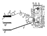
- the figure shows a schematic representation of a document processing device, for example a form reader with optical character recognition. It shows in detail an input table 1 with a first singling roll 2, which pulls the topmost document from a document stack 3 lying on the input table 1 and guided by a lateral stop and fed to a second singling roll 4.
- This second singling roller 4 is followed by a transport route with accelerator roller 5, which transfers the document to further means of transport.
- These further transport means consist of two rows of parallel pairs of rollers 6, 7, between which an optoelectric reading device, not shown, is provided.
- a deflection roller 8 which forwards the document together with a curved outer baffle (not shown) to a section 9.
- the document processing device also contains a printing device 12 which is designed as an independent structural unit and is arranged such that the print head 13 of the printing device 12 is located in front of a counter-pressure roller 14.
- This counter pressure roller 14 is made of foam, rubber or the like and is arranged next to the deflection roller 8 which does not record the full width of the document so that its apex line facing the print head 13 runs in alignment with a corresponding apex line in the document guide of the deflection roller 8.
- the entire printing device 12 is also held in guide elements (not shown) and can be pulled out tangentially to the apex line of the counterpressure roller 14 along the guide elements from the printing position (see arrow).
- the printing device works, for example, according to the thermal transfer principle, in which the print head 13 consists of a series of thermal printing dots which are activated and heated in accordance with the character code provided in the character generator. At the same time, the print head 13 is pressed with a defined contact pressure by means of a lifting magnet 15 against a thermal ink ribbon 16, which in turn is pressed against the counter-pressure roller 14. By heating the print head 13, the thermal ink ribbon 16 is heated point by point, with corresponding ink dots being transferred from the thermal ink ribbon 16 to the paper of a document transported between the thermal ink ribbon 16 and the counter-pressure roller 14.
- the thermal transfer principle has the advantage over other printing methods, in particular dot-matrix or ink-jet printing methods, that it is quieter in comparison to dot-matrix printing and that, in contrast to ink-jet printing, it is both independent of the paper quality and independent of the respective installation position in the device .
- an approximately rectangular cassette 17 is provided, which has two ribbon winding cores which can be plugged onto guide pins - winding core 18, winding core 19 - and in which the thermal ink ribbon 16 has a series of deflection rollers 20 along a longitudinal edge on the print head 13 is moved past.
- this longitudinal edge has two openings 21, 22, of which the first opening 21 in the region of the print head 13 and the second opening 22, relative to the center line running between the two tape winding cores 18, 19, is arranged mirror-symmetrically to the opening 21.
- the two approximately rectangular openings 21, 22 are selected so large that, as can be seen in the opening 21, the print head 13 can dip into the cassette 17 behind the thermal ink ribbon 16.
- a U-shaped slot opening 23, 24 for a capstan drive shaft 25 and a light barrier 26 is provided on each of the two narrow sides of the cassette 17.
- the arrangement of the individual openings 21, 22 and 23, 24 is expediently chosen so that the cassette can be used as a reversible cassette in multiple operation.
- the thermal Ribbon 16 For driving the thermal Ribbon 16 provides the aforementioned capstan drive shaft 25 and a pressure roller 27 which presses against the other side of the ribbon when the printing device 12 is in the inserted state.
- a slip coupling integrated in the capstan drive shaft 25 also causes the higher ribbon speed per se to the lower transport speed the print template moved past the print head 13 is adapted.
- the drive coupled to the drive of the capstan drive shaft 25 for the ribbon winding core 18 receiving the ribbon to be wound is also adjusted by a slip clutch so that there is only a very low driving torque for this ribbon winding core 18.
- the end of the ribbon is monitored, the position of the light barrier 26 relative to the print head 13 being selected such that all documents already in transit are still printed when the end of the ribbon passes the print head before the end of the ribbon 13 reached.
Landscapes
- Electronic Switches (AREA)
- Handling Of Sheets (AREA)
- Cash Registers Or Receiving Machines (AREA)
- Threshing Machine Elements (AREA)
- Separation, Sorting, Adjustment, Or Bending Of Sheets To Be Conveyed (AREA)
Abstract
Description
- Die Erfindung betrifft eine Vorrichtung zum Bedrucken von Belegen gemäß den Merkmalen des Oberbegriffs des Anspruchs 1.
- Moderne Belegverarbeitungsanlagen mit Einrichtungen zur optischen Zeichenerkennung werden in zunehmenden Maße mit Druckeinrichtungen ausgestattet, mit denen zusätzliche Daten, vorzugsweise Quittungsdaten, aufgedruckt werden können. Da derartige Druckeinrichtungen zwischen der Leseeinrichtung und der sich anschließenden Fachstrecke mit einem oder mehreren Ablagefächern angeordnet werden müssen, und dort üblicherweise wenig Platz zur Verfügung steht, bereitet der Einbau einer Druckeinrichtung gelegentlich große Probleme. Hinzu kommt, daß die Druckeinrichtung üblicherweise in regelmäßigen Abständen gewartet werden muß.
- Der vorliegenden Erfindung liegt daher die Aufgabe zugrunde, eine Vorrichtung zum Bedrucken von Belegen in einer Belegverarbeitungseinrichtung so auszubilden und anzuordnen, daß die Druckeinrichtung leicht zugänglich ist und einfach gewartet werden kann.
- Diese Aufgabe wird bei einer Vorrichtung der eingangs genannten Art durch die im kennzeichnenden Teil des Anspruchs 1 angegegebenen Maßnahmen gelöst. Durch die Ausbildung als selbständige Baueinheit, die bis auf die Gegenandruckrolle alle Komponenten der Druckeinrichtung enthält, kann die Vorrichtung relativ einfach aus der Gesamtanordnung entnommen und damit in einfacher Weise gewartet werden. Die Anordnung der Druckvorrichtung im Umlenkbereich der Belegtransportstrecke hat außerdem den Vorteil, daß die Druckvorrichtung ohne Eingriff in die Belegtransportstrecke seitlich angesetzt werden kann.
- Vorteilhafte Weiterbildungen der Erfindung sind in den Unteransprüchen angegeben.
- Ein Ausführungsbeispiel der Erfindung wird im folgenden anhand der Zeichnung näher erläutert.
- Die Figur zeigt in schematischer Darstellung eine Belegverarbeitungseinrichtung, beispielsweise ein Formularlesegerät mit optischer Zeichenerkennung. Sie zeigt im einzelnen einen Eingabetisch 1 mit einer ersten Vereinzelerrolle 2, die den jeweils obersten Beleg von einem auf dem Eingabetisch 1 liegend angeordneten und durch einen seitlichen Anschlag geführten Belegstapel 3 seitlich abzieht und einer zweiten Vereinzelerrolle 4 zugeführt. An diese zweite Vereinzelerrolle 4 schließt sich eine Transportstrecke mit Beschleunigerrolle 5 an, die den Beleg an weiterführende Transportmittel übergibt. Diese weiterführenden Transportmittel bestehen aus zwei Reihen parallel verlaufender Rollenpaare 6, 7, zwischen denen eine nicht dargestellte optoelektrische Leseeinrichtung vorgesehen ist. Als nächstes folgt eine Umlenkrolle 8, die den Beleg zusammen mit einem gebogenen Außenleitblech ( nicht dargestellt) an eine Fachstrecke 9 weiterleitet. Diese Fachstrecke 9 ist schwenkbar gelagert, so daß die Belege wahlweise in eines der beiden Ablagefächer 10, 11 abgelegt werden können. Die Belegverarbeitungseinrichtung enthält ferner eine Druckeinrichtung 12, die als selbständige Baueinheit ausgebildet und so angeordnet ist, daß sich der Druckkopf 13 der Druckvorrichtung 12 vor einer Gegenandruckrolle 14 befindet. Diese Gegenandruckrolle 14 besteht aus Schaumstoff, Gummi oder dergleichen und ist neben der den Beleg nicht in voller Breite erfassenden Umlenkrolle 8 so angeordnet, daß ihre dem Druckkopf 13 zugewandte Scheitellinie fluchtend zu einer entsprechenden Scheitellinie in der Belegführung der Umlenkrolle 8 verläuft. Die gesamte Druckvorrichtung 12 ist ferner in Führungselementen (nicht dargestellt) gehalten und tangential zur Scheitellinie der Gegenandruckrolle 14 entlang der Führungselemente aus der Druckposition herausziehbar (siehe Pfeil).
- Die Druckvorrichtung arbeitet beispielsweise nach dem Thermo-Transfer-Prinzip, bei dem der Druckkopf 13 aus einer Reihe von Thermo-Druckpunkten besteht, die entsprechend dem im Zeichengenerator vorgesehenen Zeichencode angesteuert und erwärmt werden. Gleichzeitig wird der Druckkopf 13 mit definiertem Anpreßdruck mit Hilfe eines Hubmagneten 15 gegen ein Thermo-Farbband 16 gedrückt, das seinerseits gegen die Gegenandruckrolle 14 gedrückt wird. Durch die Erwärmung des Druckkopfes 13 wird das Thermo-Farbband 16 punktweise erhitzt, wobei entsprechende Farbpunkte vom ThermoFarbband 16 auf das Papier eines zwischen Thermo-Farbband 16 und der Gegenandruckrolle 14 transportierten Beleges übertragen werden. Das Thermo-Transfer-Prinzip hat gegenüber anderen Druckverfahren, insbesondere Nadeldruck-oder Tintenstrahldruckverfahren, den Vorteil, daß es im Vergleich zum Nadeldruck geräuschärmer ist und daß es im Gegensatz zum Tintenstrahldruck sowohl unabhängig von der Papierqualität als auch unabhängig von der jeweiligen Einbaulage im Gerät ist. Für den Transport des Thermo-Farbbandes 16 ist beispielsweise eine etwa rechteckförmige Kassette 17 vorgesehen, die zwei auf Führungsdorne aufsteckbare Bandwickelkerne - Aufwickelkern 18, Abwickelkern 19 - aufweist und bei der das Thermo-Farbband 16 über eine Reihe von Umlenkrollen 20 entlang einer Längskante am Druckkopf 13 vorbeibewegt wird. Zu diesem Zweck weist diese Längskante zwei Öffnungen 21, 22 auf, von denen die erste Öffnung 21 im Bereich des Druckkopfes 13 und die zweite Öffnung 22, bezogen auf die zwischen den beiden Bandwickelkernen 18, 19 verlaufende Mittellinie spiegelsymmetrisch zur Öffnung 21 angeordnet ist. Die beiden etwa rechteckförmigen Öffnungen 21, 22 sind dabei so groß gewählt, daß, wie bei der Öffnung 21 ersichtlich, der Druckkopf 13 hinter dem Thermo-Farbband 16 in die Kassette 17 eintauchen kann. Schließlich ist an den beiden Schmalseiten der Kassette 17 je eine U-förmige Schlitzöffnung 23, 24 für eine Kapstan-Antriebswelle 25 bzw. eine Lichtschranke 26 vorgesehen. Die Anordnung der einzelnen Öffnungen 21, 22 bzw. 23, 24 ist zweckmäßig so gewählt, daß die Kassette als Wendekassette im Mehrfachbetrieb einsetzbar ist. Für den Antrieb des Thermo- Farbbandes 16 sorgt die bereits erwähnte Kapstan-Antriebswelle 25 und eine im eingeschobenen Zustand der Druckvorrichtung 12 von der anderen Seite des Bandes gegendrückende Andruckrolle 27. Eine in der Kapstan-Antriebswelle 25 integrierte Rutschkopplung bewirkt außerdem, daß die an sich höhere Farbbandgeschwindigkeit an die niedrigere Transportgeschwindigkeit der am Druckkopf 13 vorbeibewegten Druckvorlage angepaßt wird. Der mit dem Antrieb der Kapstan-Antriebswelle 25 gekoppelte Antrieb für den das aufzuwickelnde Farbband aufnehmenden Bandwickelkern 18 wird ebenfalls durch eine Rutschkupplung so eingestellt, daß sich für diesen Bandwickelkern 18 nur ein sehr geringes Antriebsmoment ergibt. Mit der in der U-förmigen Schlitzöffnung 24 vorgesehenen Lichtschranke 26 wird das Bandende überwacht, wobei die Lage der Lichtschranke 26 zum Druckkopf 13 so gewählt ist, daß bei einer Bandendemeldung alle bereits auf dem Transportweg befindlichen Belege noch gedruckt werden, bevor das Bandende den Druckkopf 13 erreicht.
Claims (9)
dadurch gekennzeichnet, daß die Druckvorrichtung (12), bestehend aus einem Druckkopf (13) und einem Transportsystem für ein zwischen zwei Bandwickelkernen (18, 19) am Druckkopf (13) vorbeibewegbares Farbband (16) als selbständige Baueinheit ausgebildet und so angeordnet ist, daß sich der Druckkopf (13) der Druckvorrichtung (12) vor einer Gegenandruckrolle (14) befindet, die neben der den Beleg nicht in voller Breite erfassenden Umlenkrolle (8) so gelagert ist, daß ihre dem Druckkopf (13) zugewandte Scheitellinie fluchtend zu einer entsprechenden Scheitellinie in der Belegführung der Umlenkrolle (8) verläuft und daß die Baueinheit in Führungselementen gehalten und tangential zur Scheitellinie der Gegenandruckrolle (14) entlang der Führungselemente aus der Druckvorrichtung herausziehbar ist.
dadurch gekennzeichnet, daß das Transportsystem für das Farbband als im wesentlichen rechteckförmige Kassette (17) ausgebildet ist, die auf Führungsdorne für die beiden Bandwickelkerne (18, 19) aufsetzbar ist und die an der dem Druckkopf (13) zugewandten Längskante wenigstens eine rechteckförmige Öffnung (21, 22) für den hinter dem Farbband (16) in die Kassette (17) eintauchenden Druckkopf (13) und ferner eine weitere Öffnung (23) für eine dem Aufwickelkern (18) vorgelagerte Kapstan-Antriebswelle (25) aufweist.
dadurch g e k e nn zeichnet, daß die Kapstan antriebswelle (25) eine Rutschkupplung aufweist, welche die an sich höhere Bandgeschwindigkeit an die niedrigere Transportgeschwindigkeit des zwischen Farbband (16) und Gegenandruckrolle (14) geführten Beleges anpaßt.
dadurch gekennzeichnet, daß der ebenfalls mit einer Rutschkupplung versehene Antrieb für den Aufwickelkern (18) mit dem Antrieb für die Kapstan-Antriebswelle (25) gekoppelt und ein relativ geringes Antriebsmoment aufweist.
dadurch gekennzeichnet, daß im Bereich des Abwickelkerns (19) eine weitere Öffnung (24) für eine das Farbbandende überwachende Lichtschranke (26) vorgesehen ist.
dadurch gekennzeichnet, daß die der Kapstan-Antriebswelle (25) einerseits und der Lichtschranke (26) andererseits zugeordneten Öffnungen (23, 24) an den Schmalseiten der Kassette in einer, bezogen auf die Mittellinie zwischen den beiden Bandwickelkernen (18, 19) spiegelsymmetrischen Lage zueinander angeordnet sind.
dadurch gekennzeichnet, daß als Druckvorrichtung (12) ein Thermo-Transfer-Druckkopf (13) mit Thermo-Farbband (16) vorgesehen ist.
dadurch gekennzeichnet, daß die Gegenandruckrolle (14) aus Gummi, Schaumstoff oder dergleichen besteht.
Priority Applications (1)
| Application Number | Priority Date | Filing Date | Title |
|---|---|---|---|
| AT88115019T ATE99232T1 (de) | 1987-09-28 | 1988-09-14 | Vorrichtung zum bedrucken von belegen. |
Applications Claiming Priority (2)
| Application Number | Priority Date | Filing Date | Title |
|---|---|---|---|
| DE19873732622 DE3732622A1 (de) | 1987-09-28 | 1987-09-28 | Vorrichtung zum bedrucken von belegen |
| DE3732622 | 1987-09-28 |
Publications (3)
| Publication Number | Publication Date |
|---|---|
| EP0309811A2 true EP0309811A2 (de) | 1989-04-05 |
| EP0309811A3 EP0309811A3 (de) | 1991-01-09 |
| EP0309811B1 EP0309811B1 (de) | 1993-12-29 |
Family
ID=6337034
Family Applications (1)
| Application Number | Title | Priority Date | Filing Date |
|---|---|---|---|
| EP88115019A Expired - Lifetime EP0309811B1 (de) | 1987-09-28 | 1988-09-14 | Vorrichtung zum Bedrucken von Belegen |
Country Status (4)
| Country | Link |
|---|---|
| EP (1) | EP0309811B1 (de) |
| AT (1) | ATE99232T1 (de) |
| DE (2) | DE3732622A1 (de) |
| ES (1) | ES2047518T3 (de) |
Families Citing this family (1)
| Publication number | Priority date | Publication date | Assignee | Title |
|---|---|---|---|---|
| DE10039699C2 (de) | 2000-08-14 | 2003-12-04 | Wincor Nixdorf Int Gmbh | Vorrichtung zum Bearbeiten von Wettscheinen |
Family Cites Families (4)
| Publication number | Priority date | Publication date | Assignee | Title |
|---|---|---|---|---|
| DE2333250C3 (de) * | 1973-06-29 | 1976-01-08 | K.K. Copal, Tokio | Thermodrucker |
| US4422376A (en) * | 1980-02-09 | 1983-12-27 | Teraoka Seikosho Co., Ltd. | Printing control apparatus for a label printer |
| EP0111297B1 (de) * | 1982-12-07 | 1989-08-09 | Kabushiki Kaisha Toshiba | Thermischer Druckapparat |
| US4614949A (en) * | 1983-10-20 | 1986-09-30 | Ricoh Company, Ltd. | Transfer-type thermal printer |
-
1987
- 1987-09-28 DE DE19873732622 patent/DE3732622A1/de not_active Withdrawn
-
1988
- 1988-09-14 AT AT88115019T patent/ATE99232T1/de not_active IP Right Cessation
- 1988-09-14 ES ES88115019T patent/ES2047518T3/es not_active Expired - Lifetime
- 1988-09-14 DE DE88115019T patent/DE3886644D1/de not_active Expired - Fee Related
- 1988-09-14 EP EP88115019A patent/EP0309811B1/de not_active Expired - Lifetime
Also Published As
| Publication number | Publication date |
|---|---|
| DE3886644D1 (de) | 1994-02-10 |
| DE3732622A1 (de) | 1989-04-06 |
| ES2047518T3 (es) | 1994-03-01 |
| ATE99232T1 (de) | 1994-01-15 |
| EP0309811B1 (de) | 1993-12-29 |
| EP0309811A3 (de) | 1991-01-09 |
Similar Documents
| Publication | Publication Date | Title |
|---|---|---|
| DE69020666T2 (de) | Kartenausgabegerät. | |
| EP0052408B1 (de) | Schreibwerk mit einem Aufzeichnungsorgan und Mitteln zum Umlenken eines Aufzeichnungsträgers | |
| DE69801862T2 (de) | Drucker mit beweglichem Papierführungsmechanismus | |
| EP0099120B1 (de) | Universelle Papiertransporteinrichtung für Einzelblätter und Endlospapier in Zeilendruckeinrichtungen | |
| DE2716396B2 (de) | Vorrichtung zur Papierführung in Druckgeräten, insbesondere bei Datenoder Fernschreibmaschinen | |
| DE3941315A1 (de) | Vorrichtung zum vermeiden einer schieflage geschnittener papierbogen | |
| DE4023499C2 (de) | Etikettendrucker mit Selbstlademechanismus | |
| DE69511308T2 (de) | Druckvorrichtung und Steuerungsverfahren dafür | |
| DE2711704B2 (de) | Fahrkartendrucker | |
| DE2734890C3 (de) | Aufzeichnungsträgerpositioniervorrichtung | |
| EP0035178B1 (de) | Vorrichtung für Druckeinrichtungen zur Ablage von blattförmigen Aufzeichnungsträgern | |
| EP3838604B1 (de) | Etikettendrucker | |
| EP0344097A1 (de) | Einrichtung für den Transport von Aufzeichnungsträgern in Büromaschinen, inbesondere für Belege in Belegverarbeitungsgeräten | |
| DE69020945T2 (de) | Aufzeichnungsvorrichtung. | |
| EP0309812A2 (de) | Farbband-Kassette | |
| DE2526474A1 (de) | Verfahren und vorrichtung zum sortieren von kartenfoermigen informationstraegern | |
| EP0123310B1 (de) | Papiertransportvorrichtung für Einzelblätter und Endlospapier in Druckeinrichtungen | |
| EP0309811B1 (de) | Vorrichtung zum Bedrucken von Belegen | |
| DE68917395T2 (de) | Vorrichtung zum Transportieren von Aufzeichnungsträgern. | |
| WO1994022117A1 (de) | Belegdruckeinrichtung sowie ein verfahren zum erfassen von belegen über kontrollkennzeichen unter verwendung dieser belegdruckeinrichtung | |
| EP0199083A2 (de) | Wertscheingeber | |
| DE102010048921A1 (de) | Verfahren und Einrichtung zum Erfassen und Bedrucken von Dokumenten | |
| DE60004741T2 (de) | Drucker und Steuerungsverfahren dafür | |
| DE3509738A1 (de) | Aufzeichnungsgeraet | |
| EP0690791B1 (de) | Belegdruckeinrichtung mit einer einrichtung und einem verfahren zur abdruckkontrolle |
Legal Events
| Date | Code | Title | Description |
|---|---|---|---|
| PUAI | Public reference made under article 153(3) epc to a published international application that has entered the european phase |
Free format text: ORIGINAL CODE: 0009012 |
|
| AK | Designated contracting states |
Kind code of ref document: A2 Designated state(s): AT BE CH DE ES FR GB IT LI NL SE |
|
| PUAL | Search report despatched |
Free format text: ORIGINAL CODE: 0009013 |
|
| AK | Designated contracting states |
Kind code of ref document: A3 Designated state(s): AT BE CH DE ES FR GB IT LI NL SE |
|
| 17P | Request for examination filed |
Effective date: 19901220 |
|
| 17Q | First examination report despatched |
Effective date: 19921002 |
|
| GRAA | (expected) grant |
Free format text: ORIGINAL CODE: 0009210 |
|
| AK | Designated contracting states |
Kind code of ref document: B1 Designated state(s): AT BE CH DE ES FR GB IT LI NL SE |
|
| REF | Corresponds to: |
Ref document number: 99232 Country of ref document: AT Date of ref document: 19940115 Kind code of ref document: T |
|
| REF | Corresponds to: |
Ref document number: 3886644 Country of ref document: DE Date of ref document: 19940210 |
|
| REG | Reference to a national code |
Ref country code: ES Ref legal event code: FG2A Ref document number: 2047518 Country of ref document: ES Kind code of ref document: T3 |
|
| ITF | It: translation for a ep patent filed | ||
| GBT | Gb: translation of ep patent filed (gb section 77(6)(a)/1977) |
Effective date: 19940304 |
|
| ET | Fr: translation filed | ||
| PGFP | Annual fee paid to national office [announced via postgrant information from national office to epo] |
Ref country code: AT Payment date: 19940824 Year of fee payment: 7 |
|
| PGFP | Annual fee paid to national office [announced via postgrant information from national office to epo] |
Ref country code: SE Payment date: 19940829 Year of fee payment: 7 |
|
| PGFP | Annual fee paid to national office [announced via postgrant information from national office to epo] |
Ref country code: ES Payment date: 19940905 Year of fee payment: 7 |
|
| PGFP | Annual fee paid to national office [announced via postgrant information from national office to epo] |
Ref country code: BE Payment date: 19940912 Year of fee payment: 7 |
|
| PGFP | Annual fee paid to national office [announced via postgrant information from national office to epo] |
Ref country code: FR Payment date: 19940920 Year of fee payment: 7 |
|
| PG25 | Lapsed in a contracting state [announced via postgrant information from national office to epo] |
Ref country code: LI Effective date: 19940930 Ref country code: CH Effective date: 19940930 |
|
| PGFP | Annual fee paid to national office [announced via postgrant information from national office to epo] |
Ref country code: NL Payment date: 19940930 Year of fee payment: 7 |
|
| PLBE | No opposition filed within time limit |
Free format text: ORIGINAL CODE: 0009261 |
|
| STAA | Information on the status of an ep patent application or granted ep patent |
Free format text: STATUS: NO OPPOSITION FILED WITHIN TIME LIMIT |
|
| 26N | No opposition filed | ||
| EAL | Se: european patent in force in sweden |
Ref document number: 88115019.7 |
|
| REG | Reference to a national code |
Ref country code: CH Ref legal event code: PL |
|
| PG25 | Lapsed in a contracting state [announced via postgrant information from national office to epo] |
Ref country code: AT Effective date: 19950914 |
|
| PG25 | Lapsed in a contracting state [announced via postgrant information from national office to epo] |
Ref country code: SE Effective date: 19950915 Ref country code: ES Free format text: LAPSE BECAUSE OF THE APPLICANT RENOUNCES Effective date: 19950915 |
|
| PG25 | Lapsed in a contracting state [announced via postgrant information from national office to epo] |
Ref country code: BE Effective date: 19950930 |
|
| BERE | Be: lapsed |
Owner name: COMPUTER G.- KONSTANZ M.B.H. Effective date: 19950930 |
|
| PG25 | Lapsed in a contracting state [announced via postgrant information from national office to epo] |
Ref country code: NL Effective date: 19960401 |
|
| PG25 | Lapsed in a contracting state [announced via postgrant information from national office to epo] |
Ref country code: FR Effective date: 19960531 |
|
| NLV4 | Nl: lapsed or anulled due to non-payment of the annual fee |
Effective date: 19960401 |
|
| EUG | Se: european patent has lapsed |
Ref document number: 88115019.7 |
|
| REG | Reference to a national code |
Ref country code: FR Ref legal event code: ST |
|
| PGFP | Annual fee paid to national office [announced via postgrant information from national office to epo] |
Ref country code: GB Payment date: 19980817 Year of fee payment: 11 |
|
| PG25 | Lapsed in a contracting state [announced via postgrant information from national office to epo] |
Ref country code: GB Free format text: LAPSE BECAUSE OF NON-PAYMENT OF DUE FEES Effective date: 19990914 |
|
| REG | Reference to a national code |
Ref country code: ES Ref legal event code: FD2A Effective date: 19991007 |
|
| GBPC | Gb: european patent ceased through non-payment of renewal fee |
Effective date: 19990914 |
|
| PGFP | Annual fee paid to national office [announced via postgrant information from national office to epo] |
Ref country code: DE Payment date: 20000911 Year of fee payment: 13 |
|
| PG25 | Lapsed in a contracting state [announced via postgrant information from national office to epo] |
Ref country code: DE Free format text: LAPSE BECAUSE OF NON-PAYMENT OF DUE FEES Effective date: 20020501 |
|
| PG25 | Lapsed in a contracting state [announced via postgrant information from national office to epo] |
Ref country code: IT Free format text: LAPSE BECAUSE OF NON-PAYMENT OF DUE FEES;WARNING: LAPSES OF ITALIAN PATENTS WITH EFFECTIVE DATE BEFORE 2007 MAY HAVE OCCURRED AT ANY TIME BEFORE 2007. THE CORRECT EFFECTIVE DATE MAY BE DIFFERENT FROM THE ONE RECORDED. Effective date: 20050914 |