EP0309847B1 - Kontaktloser Messer der Position eines ersten Stücks bezüglich eines zweiten Stücks - Google Patents
Kontaktloser Messer der Position eines ersten Stücks bezüglich eines zweiten Stücks Download PDFInfo
- Publication number
- EP0309847B1 EP0309847B1 EP88115313A EP88115313A EP0309847B1 EP 0309847 B1 EP0309847 B1 EP 0309847B1 EP 88115313 A EP88115313 A EP 88115313A EP 88115313 A EP88115313 A EP 88115313A EP 0309847 B1 EP0309847 B1 EP 0309847B1
- Authority
- EP
- European Patent Office
- Prior art keywords
- magnet
- axle
- measuring
- measuring element
- respect
- Prior art date
- Legal status (The legal status is an assumption and is not a legal conclusion. Google has not performed a legal analysis and makes no representation as to the accuracy of the status listed.)
- Expired - Lifetime
Links
Images

Classifications
-
- G—PHYSICS
- G01—MEASURING; TESTING
- G01B—MEASURING LENGTH, THICKNESS OR SIMILAR LINEAR DIMENSIONS; MEASURING ANGLES; MEASURING AREAS; MEASURING IRREGULARITIES OF SURFACES OR CONTOURS
- G01B7/00—Measuring arrangements characterised by the use of electric or magnetic techniques
- G01B7/02—Measuring arrangements characterised by the use of electric or magnetic techniques for measuring length, width or thickness
- G01B7/023—Measuring arrangements characterised by the use of electric or magnetic techniques for measuring length, width or thickness for measuring distance between sensor and object
-
- G—PHYSICS
- G01—MEASURING; TESTING
- G01B—MEASURING LENGTH, THICKNESS OR SIMILAR LINEAR DIMENSIONS; MEASURING ANGLES; MEASURING AREAS; MEASURING IRREGULARITIES OF SURFACES OR CONTOURS
- G01B7/00—Measuring arrangements characterised by the use of electric or magnetic techniques
- G01B7/28—Measuring arrangements characterised by the use of electric or magnetic techniques for measuring contours or curvatures
Definitions
- the present invention relates to a device for non-contact measurement of the position of a first part with respect to a second ferromagnetic part in a direction tangent to the surface separating them, through the latter, and independently of variations in the position in a direction normal to this surface.
- the first part is linked to a railway axle and the second part is one of the rails of the track on which this axle rolls, the measurement being transverse to the axis of the track.
- the switches, switches, level crossings, etc. it is difficult to put a sensor under the running surface, and that the high travel speeds require a contactless sensor.
- An object of the invention is to provide a simple and robust device capable of withstanding the incessant vibrations and shocks to which the railway axle is subjected and of making it independent of vertical variations (wheel wear, pitching of the axle, suspended device ).
- the first part comprises a sealed box, fixed to the axle with possibly a purely vertical suspension, in which a magnet can move in the direction of measurement; this movement is either linear or rotary with a small angle and in this case its axis is preferably located in the plane of symmetry of the rail in the middle position.
- the magnet and the second rail part constitute a magnetic circuit with variable reluctance.
- the interaction forces between the magnet and the rail keep them stably in a given transverse position, independent of the vertical position (minimum reluctance position in transverse).
- the relative position of the magnet relative to the box is then measured by a conventional sensor.
- a synchro-resolver is used for this measurement.
- the rotation is preferably of vertical axis.
- the embodiment which will be described relates to a device for measuring the position of an axle with respect to the track.
- the reference 1 generally designates the measuring device, fixed to an axle not shown, and arranged so as to remain close to a rail 2 on which the axle rolls.
- the device comprises a casing 3 of non-magnetic material delimiting a chamber 4 closed by a plate 5 of the same material.
- a shaft 6 can pivot in two bearings 7 and 8 produced for example with needle bearings or in polytetrafluoroethylene (registered trademark Teflon).
- the casing is fixed to the axle so that the shaft 6 is on average in the plane P of longitudinal symmetry of the rail 2.
- the shaft carries a folded sheet 9, made of non-magnetic metal (stainless steel for example), on which a permanent magnet 10 is fixed.
- the magnetization direction of the magnet can be perpendicular to the aforementioned plane P.
- the magnet is preferably a parallelepiped bar made of samarium-cobalt.
- the plate 5 comprises a thinned portion 5A so that the magnet is placed near the rail and that the magnetic circuit constituted by the magnet 10 and the rail 2 has a relatively low reluctance.
- the magnet is then subject to remain in the same transverse position with respect to the rail.
- a transverse displacement of the casing relative to the rail causes a rotation of the shaft 6.
- the measurement of the rotation of the shaft 6 provides the measurement of a degree of freedom of the axle.
- Two devices of this type placed respectively in front of and behind the axle, provide its angular position and its transverse position relative to the rail.
- any type of measuring device can be used, but it is advantageous to use a synchro-resolver 11 which can be placed in a cavity in the upper part of the casing and fixed by an O-ring 12 ensuring a tight seal. vis-à-vis external agents.
- the cavity is closed by a cover 13.
- a passage 14 in the housing makes it possible to place the electrical connecting wires of the synchro-resolver.
- the metal plate 5 is the seat, when the magnet 10 moves, of eddy currents which have the effect of damping the movement of the magnet.
- the device is therefore not very sensitive to the multiple shocks and vibrations generated by an axle moving on a rail.
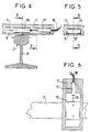
- FIGS 4 to 6 illustrate an alternative embodiment of the device of the invention in which the magnet is subject to move in translation in the housing.
- the magnet 10 is subjected to undergo only translational movements inside the casing 3-5; a plastic coating 15 inside the box facilitates the sliding of the magnet.
- the best sensitivity is obtained by placing the magnet in such a way that its direction of magnetization (therefore of movement) is substantially in a horizontal plane and perpendicular to the rail.
- the displacement of the magnet is measured electrically by providing the magnet with a rod 16 which is integral with it and forms part of a linear displacement sensor which can be a capacitive or inductive circuit 17 placed in a cavity of the casing and provided of output conductors 18.
- This variant embodiment has the same qualities as the device described with reference to FIGS. 1 to 3.
Landscapes
- Physics & Mathematics (AREA)
- General Physics & Mathematics (AREA)
- Measurement Of Length, Angles, Or The Like Using Electric Or Magnetic Means (AREA)
- Transmission And Conversion Of Sensor Element Output (AREA)
- A Measuring Device Byusing Mechanical Method (AREA)
- Length Measuring Devices With Unspecified Measuring Means (AREA)
- Coupling Device And Connection With Printed Circuit (AREA)
- Manufacturing Of Electrical Connectors (AREA)
- Length-Measuring Instruments Using Mechanical Means (AREA)
- Knives (AREA)
Claims (7)
- Vorrichtung zur kontaktlosen Messung der Position eines ersten Körpers relativ zu einem zweiten Körper, dadurch gekennzeichnet, daß sie einen Magneten (10) aufweist, der mit dem ersten Körper mindestens einen Freiheitsgrad tangential zur Meßrichtung besitzt und mit einem mit dem zweiten Körper verbundenen magnetischen Abschnitt zusammenwirkt, und daß sie ein Organ (11) zum Messen der Position des Magneten relativ zum ersten Körper aufweist.
- Vorrichtung nach Anspruch 1, dadurch gekennzeichnet, daß der Magnet (10) starr mit einer Welle (6) verbunden ist, die sich relativ zum ersten Körper drehen kann, wobei das Meßorgan (11) ein Winkelsensor ist.
- Vorrichtung nach Anspruch 1, dadurch gekennzeichnet, daß der Magnet (10) so gefaßt ist, daß er sich relativ zum ersten Körper nur in Längsrichtung verschieben kann, wobei das Meßorgan ein Linearverschiebungssensor (17) ist.
- Vorrichtung nach einem der Ansprüche 1 und 2, dadurch gekennzeichnet, daß die Achse, der Magnet und das Meßorgan im Inneren eines dichten Gehäuses angeordnet sind, das am ersten Körper befestigt ist.
- Vorrichtung nach einem der Ansprüche 2 und 4, dadurch gekennzeichnet, daß das Meßorgan (11) ein Synchro-Resolver ist.
- Vorrichtung nach einem der Ansprüche 1 bis 5, dadurch gekennzeichnet, daß der erste Körper ein Querträger einer Radachse für ein Schienenfahrzeug ist, während der zweite Körper eine (2) der Schienen des Fahrwegs der Radachse bildet.
- Vorrichtung nach Anspruch 6, dadurch gekennzeichnet, daß die Magnetisierungsrichtung des Magneten (10) im wesentlichen senkrecht zu dieser Schiene (2) verläuft.
Priority Applications (1)
| Application Number | Priority Date | Filing Date | Title |
|---|---|---|---|
| AT88115313T ATE71712T1 (de) | 1987-09-28 | 1988-09-19 | Kontaktloser messer der position eines ersten stuecks bezueglich eines zweiten stuecks. |
Applications Claiming Priority (2)
| Application Number | Priority Date | Filing Date | Title |
|---|---|---|---|
| FR8713380A FR2621114B1 (fr) | 1987-09-28 | 1987-09-28 | Dispositif pour la mesure sans contact de la position d'une premiere piece par rapport a une seconde piece |
| FR8713380 | 1987-09-28 |
Publications (2)
| Publication Number | Publication Date |
|---|---|
| EP0309847A1 EP0309847A1 (de) | 1989-04-05 |
| EP0309847B1 true EP0309847B1 (de) | 1992-01-15 |
Family
ID=9355287
Family Applications (1)
| Application Number | Title | Priority Date | Filing Date |
|---|---|---|---|
| EP88115313A Expired - Lifetime EP0309847B1 (de) | 1987-09-28 | 1988-09-19 | Kontaktloser Messer der Position eines ersten Stücks bezüglich eines zweiten Stücks |
Country Status (7)
| Country | Link |
|---|---|
| US (1) | US4912406A (de) |
| EP (1) | EP0309847B1 (de) |
| AT (1) | ATE71712T1 (de) |
| CA (1) | CA1297966C (de) |
| DE (1) | DE3867783D1 (de) |
| ES (1) | ES2029704T3 (de) |
| FR (1) | FR2621114B1 (de) |
Families Citing this family (5)
| Publication number | Priority date | Publication date | Assignee | Title |
|---|---|---|---|---|
| US5214379A (en) * | 1992-06-25 | 1993-05-25 | The United States Of America As Represented By The Administrator Of The National Aeronautics And Space Administration | Method and apparatus for deflection measurements using eddy current effects |
| NL9400955A (nl) * | 1994-03-11 | 1995-10-02 | Mathijs Maria Johannes Engels | Inrichting en werkwijze voor het contactloos meten aan een staaf uit ferro-magnetisch materiaal. |
| CN106671208B (zh) * | 2016-12-16 | 2018-09-21 | 重庆坤秀门窗有限公司 | 一种散热型木门切割锯 |
| CN109425288A (zh) * | 2017-09-02 | 2019-03-05 | 湖南北斗星空自动化科技有限公司 | 一种利用磁致伸缩位移测距原理自动监测轨道板裂缝的方法 |
| CN109029228B (zh) * | 2018-05-30 | 2021-01-05 | 中南大学 | 一种用于测量轨道车辆与钢轨相对偏移的系统及方法 |
Family Cites Families (11)
| Publication number | Priority date | Publication date | Assignee | Title |
|---|---|---|---|---|
| US2749663A (en) * | 1950-12-12 | 1956-06-12 | Jerome H Lemelson | Toy mine detector |
| US3515984A (en) * | 1968-08-05 | 1970-06-02 | Cleveland Technical Center Inc | Apparatus and method for measuring distance between spaced magnetic members |
| GB1453542A (en) * | 1974-12-03 | 1976-10-27 | Automatisk Doserings Kompensat | Railway vehicle including a device for reducing lateral move ments thereof caused by iregularities in a rail carrying the vehicle |
| US4005601A (en) * | 1975-08-29 | 1977-02-01 | Amac, Inc. | Apparatus for detecting rail discontinuities |
| JPS57173701A (en) * | 1981-04-21 | 1982-10-26 | Japanese National Railways<Jnr> | Eddy current type device and method for measuring rail displacement |
| DE3216321C1 (de) * | 1982-05-03 | 1983-09-29 | Daimler-Benz Ag, 7000 Stuttgart | Magnetisch betaetigter elektrischer Schalter |
| DE3345791A1 (de) * | 1983-12-17 | 1985-06-27 | Vdo Adolf Schindling Ag, 6000 Frankfurt | Beruehrungsloser elektronischer winkelgeber |
| US4726627A (en) * | 1984-10-22 | 1988-02-23 | Kelsey-Hayes Co. | Deceleration sensor for an electric brake controller |
| US4717873A (en) * | 1985-11-12 | 1988-01-05 | Westinghouse Electric Corp. | Magnetic displacement transducer system having a magnet that is movable in a tube whose interior is exposed to a fluid and having at least one magnetometer outside the tube |
| JPH07113551B2 (ja) * | 1986-07-21 | 1995-12-06 | ティーディーケイ株式会社 | 傾斜センサ |
| US4820888A (en) * | 1988-05-16 | 1989-04-11 | Shields Larry E | Tilt switch replacing mercury switches |
-
1987
- 1987-09-28 FR FR8713380A patent/FR2621114B1/fr not_active Expired - Fee Related
-
1988
- 1988-09-19 DE DE8888115313T patent/DE3867783D1/de not_active Expired - Lifetime
- 1988-09-19 AT AT88115313T patent/ATE71712T1/de not_active IP Right Cessation
- 1988-09-19 ES ES198888115313T patent/ES2029704T3/es not_active Expired - Lifetime
- 1988-09-19 EP EP88115313A patent/EP0309847B1/de not_active Expired - Lifetime
- 1988-09-26 CA CA000578447A patent/CA1297966C/fr not_active Expired - Lifetime
- 1988-09-28 US US07/250,808 patent/US4912406A/en not_active Expired - Fee Related
Also Published As
| Publication number | Publication date |
|---|---|
| EP0309847A1 (de) | 1989-04-05 |
| FR2621114A1 (fr) | 1989-03-31 |
| FR2621114B1 (fr) | 1991-05-17 |
| CA1297966C (fr) | 1992-03-24 |
| US4912406A (en) | 1990-03-27 |
| ATE71712T1 (de) | 1992-02-15 |
| DE3867783D1 (de) | 1992-02-27 |
| ES2029704T3 (es) | 1992-09-01 |
Similar Documents
| Publication | Publication Date | Title |
|---|---|---|
| EP0514530B1 (de) | Magnetischer lage- und geschwindigkeitssensor mit hallsonde | |
| EP0544576B1 (de) | Linear Servomotor mit veränderlicher Reluktanz | |
| EP1269133B1 (de) | Positionssensor, insbesondere zur messung des drehmoments einer lenksäule | |
| EP0453824B1 (de) | Sensor zur Messung der relativen transversalen Verschiebung eines leitenden Stückes in länglicher Form | |
| US5982170A (en) | Rotary position sensor with improved bearing tolerance | |
| US4398773A (en) | Magnetic suspension assembly for a rotor | |
| EP0198724A1 (de) | Durch Mikrobearbeitung hergestellter Beschleunigungsmesser mit elektrostatischer Rückstellung | |
| US5047629A (en) | Position and motion detector with magnetic coupling and optical detection | |
| EP0388584A1 (de) | Vorrichtung zur Ermittlung der Lage einer mit einem elektrisch diskontinuierlich leitenden Band umgebenen rotierenden Stahlwelle sowie Verfahren zur Herstellung des Bandes | |
| JPH02263113A (ja) | 多回転式軸位置センサー | |
| EP0814338A1 (de) | Schwenkkugellager mit eingebautem Messaufnehmer | |
| EP0309847A1 (de) | Kontaktloser Messer der Position eines ersten Stücks bezüglich eines zweiten Stücks | |
| US7463023B1 (en) | Non-contacting rotary and linear travel sensor | |
| EP2504665A1 (de) | Messverfahren und magnetsensor zur kontaktlosen erkennung von bewegungen | |
| EP3111173A1 (de) | Magnetsensor zur bestimmung der relativen position zwischen einem magnetisierten ziel und einem messsystem | |
| CN106537081B (zh) | 自动横向应变伸长计架构 | |
| US4692614A (en) | Rotational motion fluid loop sensor using magnetically levitated detecting element | |
| FR2505496A1 (fr) | Dispositif capteur de force pour appareil de mesure et appareil de mesure, notamment appareil de pesage, equipe d'un tel dispositif | |
| JPS6217421A (ja) | ボ−ルジヨイント | |
| WO2022090499A1 (fr) | Dispositif de détection du couplage capacitif entre un objet et une surface de détection | |
| JP3146552B2 (ja) | 位置検出センサ | |
| SU1015304A1 (ru) | Дифференциальный емкостной датчик направлени и скорости вращени | |
| FI73831C (fi) | Givare foer maetning av mekaniska egenskaper hos en roerlig aemnesbana. | |
| NL8900932A (nl) | Werkwijze en inrichting voor het meten van de dikte van een smeermiddelfilm. | |
| CH654913A5 (en) | Differential expansion sensor |
Legal Events
| Date | Code | Title | Description |
|---|---|---|---|
| PUAI | Public reference made under article 153(3) epc to a published international application that has entered the european phase |
Free format text: ORIGINAL CODE: 0009012 |
|
| AK | Designated contracting states |
Kind code of ref document: A1 Designated state(s): AT BE CH DE ES FR GB IT LI NL SE |
|
| 17P | Request for examination filed |
Effective date: 19890920 |
|
| RAP1 | Party data changed (applicant data changed or rights of an application transferred) |
Owner name: REGIE AUTONOME DES TRANSPORTS PARISIENS Owner name: INSTITUT NATIONAL DE RECHERCHE SUR LES TRANSPORTS Owner name: GEC ALSTHOM SA |
|
| 17Q | First examination report despatched |
Effective date: 19910422 |
|
| GRAA | (expected) grant |
Free format text: ORIGINAL CODE: 0009210 |
|
| AK | Designated contracting states |
Kind code of ref document: B1 Designated state(s): AT BE CH DE ES FR GB IT LI NL SE |
|
| REF | Corresponds to: |
Ref document number: 71712 Country of ref document: AT Date of ref document: 19920215 Kind code of ref document: T |
|
| REF | Corresponds to: |
Ref document number: 3867783 Country of ref document: DE Date of ref document: 19920227 |
|
| GBT | Gb: translation of ep patent filed (gb section 77(6)(a)/1977) | ||
| ITF | It: translation for a ep patent filed | ||
| REG | Reference to a national code |
Ref country code: ES Ref legal event code: FG2A Ref document number: 2029704 Country of ref document: ES Kind code of ref document: T3 |
|
| PLBE | No opposition filed within time limit |
Free format text: ORIGINAL CODE: 0009261 |
|
| STAA | Information on the status of an ep patent application or granted ep patent |
Free format text: STATUS: NO OPPOSITION FILED WITHIN TIME LIMIT |
|
| 26N | No opposition filed | ||
| EAL | Se: european patent in force in sweden |
Ref document number: 88115313.4 |
|
| PGFP | Annual fee paid to national office [announced via postgrant information from national office to epo] |
Ref country code: ES Payment date: 19950906 Year of fee payment: 8 |
|
| PGFP | Annual fee paid to national office [announced via postgrant information from national office to epo] |
Ref country code: NL Payment date: 19950929 Year of fee payment: 8 Ref country code: AT Payment date: 19950929 Year of fee payment: 8 |
|
| PGFP | Annual fee paid to national office [announced via postgrant information from national office to epo] |
Ref country code: SE Payment date: 19960812 Year of fee payment: 9 Ref country code: GB Payment date: 19960812 Year of fee payment: 9 |
|
| PGFP | Annual fee paid to national office [announced via postgrant information from national office to epo] |
Ref country code: DE Payment date: 19960814 Year of fee payment: 9 |
|
| PGFP | Annual fee paid to national office [announced via postgrant information from national office to epo] |
Ref country code: CH Payment date: 19960822 Year of fee payment: 9 |
|
| PGFP | Annual fee paid to national office [announced via postgrant information from national office to epo] |
Ref country code: BE Payment date: 19960903 Year of fee payment: 9 |
|
| PGFP | Annual fee paid to national office [announced via postgrant information from national office to epo] |
Ref country code: FR Payment date: 19960912 Year of fee payment: 9 |
|
| PG25 | Lapsed in a contracting state [announced via postgrant information from national office to epo] |
Ref country code: AT Effective date: 19960919 |
|
| PG25 | Lapsed in a contracting state [announced via postgrant information from national office to epo] |
Ref country code: ES Free format text: LAPSE BECAUSE OF THE APPLICANT RENOUNCES Effective date: 19960920 |
|
| PG25 | Lapsed in a contracting state [announced via postgrant information from national office to epo] |
Ref country code: NL Effective date: 19970401 |
|
| NLV4 | Nl: lapsed or anulled due to non-payment of the annual fee |
Effective date: 19970401 |
|
| PG25 | Lapsed in a contracting state [announced via postgrant information from national office to epo] |
Ref country code: GB Free format text: LAPSE BECAUSE OF NON-PAYMENT OF DUE FEES Effective date: 19970919 |
|
| PG25 | Lapsed in a contracting state [announced via postgrant information from national office to epo] |
Ref country code: SE Free format text: LAPSE BECAUSE OF NON-PAYMENT OF DUE FEES Effective date: 19970920 |
|
| PG25 | Lapsed in a contracting state [announced via postgrant information from national office to epo] |
Ref country code: LI Free format text: LAPSE BECAUSE OF NON-PAYMENT OF DUE FEES Effective date: 19970930 Ref country code: FR Free format text: THE PATENT HAS BEEN ANNULLED BY A DECISION OF A NATIONAL AUTHORITY Effective date: 19970930 Ref country code: CH Free format text: LAPSE BECAUSE OF NON-PAYMENT OF DUE FEES Effective date: 19970930 Ref country code: BE Free format text: LAPSE BECAUSE OF NON-PAYMENT OF DUE FEES Effective date: 19970930 |
|
| BERE | Be: lapsed |
Owner name: REGIE AUTONOME DES TRANSPORTS PARISIENS Effective date: 19970930 Owner name: INSTITUT NATIONAL DE RECHERCHE SUR LES TRANSPORTS Effective date: 19970930 Owner name: S.A. GEC ALSTHOM Effective date: 19970930 |
|
| GBPC | Gb: european patent ceased through non-payment of renewal fee |
Effective date: 19970919 |
|
| REG | Reference to a national code |
Ref country code: CH Ref legal event code: PL |
|
| PG25 | Lapsed in a contracting state [announced via postgrant information from national office to epo] |
Ref country code: DE Free format text: LAPSE BECAUSE OF NON-PAYMENT OF DUE FEES Effective date: 19980603 |
|
| EUG | Se: european patent has lapsed |
Ref document number: 88115313.4 |
|
| REG | Reference to a national code |
Ref country code: FR Ref legal event code: ST |
|
| REG | Reference to a national code |
Ref country code: ES Ref legal event code: FD2A Effective date: 19991007 |
|
| PG25 | Lapsed in a contracting state [announced via postgrant information from national office to epo] |
Ref country code: IT Free format text: LAPSE BECAUSE OF NON-PAYMENT OF DUE FEES;WARNING: LAPSES OF ITALIAN PATENTS WITH EFFECTIVE DATE BEFORE 2007 MAY HAVE OCCURRED AT ANY TIME BEFORE 2007. THE CORRECT EFFECTIVE DATE MAY BE DIFFERENT FROM THE ONE RECORDED. Effective date: 20050919 |