EP0309927A2 - Détecteur pour image à distance - Google Patents
Détecteur pour image à distance Download PDFInfo
- Publication number
- EP0309927A2 EP0309927A2 EP88115625A EP88115625A EP0309927A2 EP 0309927 A2 EP0309927 A2 EP 0309927A2 EP 88115625 A EP88115625 A EP 88115625A EP 88115625 A EP88115625 A EP 88115625A EP 0309927 A2 EP0309927 A2 EP 0309927A2
- Authority
- EP
- European Patent Office
- Prior art keywords
- distance image
- sensor
- gate
- image sensor
- ccd
- Prior art date
- Legal status (The legal status is an assumption and is not a legal conclusion. Google has not performed a legal analysis and makes no representation as to the accuracy of the status listed.)
- Granted
Links
Images


Classifications
-
- G—PHYSICS
- G01—MEASURING; TESTING
- G01S—RADIO DIRECTION-FINDING; RADIO NAVIGATION; DETERMINING DISTANCE OR VELOCITY BY USE OF RADIO WAVES; LOCATING OR PRESENCE-DETECTING BY USE OF THE REFLECTION OR RERADIATION OF RADIO WAVES; ANALOGOUS ARRANGEMENTS USING OTHER WAVES
- G01S7/00—Details of systems according to groups G01S13/00, G01S15/00, G01S17/00
- G01S7/48—Details of systems according to groups G01S13/00, G01S15/00, G01S17/00 of systems according to group G01S17/00
- G01S7/483—Details of pulse systems
- G01S7/486—Receivers
-
- G—PHYSICS
- G01—MEASURING; TESTING
- G01S—RADIO DIRECTION-FINDING; RADIO NAVIGATION; DETERMINING DISTANCE OR VELOCITY BY USE OF RADIO WAVES; LOCATING OR PRESENCE-DETECTING BY USE OF THE REFLECTION OR RERADIATION OF RADIO WAVES; ANALOGOUS ARRANGEMENTS USING OTHER WAVES
- G01S17/00—Systems using the reflection or reradiation of electromagnetic waves other than radio waves, e.g. lidar systems
- G01S17/02—Systems using the reflection of electromagnetic waves other than radio waves
- G01S17/06—Systems determining position data of a target
- G01S17/08—Systems determining position data of a target for measuring distance only
- G01S17/10—Systems determining position data of a target for measuring distance only using transmission of interrupted, pulse-modulated waves
- G01S17/18—Systems determining position data of a target for measuring distance only using transmission of interrupted, pulse-modulated waves wherein range gates are used
Definitions
- the invention relates to a distance image sensor with a pulsed light source according to the preamble of claim 1.
- range image sensors are only known for radar arrangements, as can be seen for example from DE-AS 12 34 811.
- An aircraft radar device for collision warning is disclosed here, in which the reflected signal is fed to gate circuits with downstream integrators. Controlled opening of the respective gates leads the reflected signal into the correct gate according to the associated distance, and the distance is displayed after integrating several emitted signals.
- this device is very sensitive to the weather and is too complex to construct and function elements.
- a device for determining the triggering distance from a missile to be moved to a target has become known, in which by means of a leach time measurement of at least two chronologically successive and thus different distances assigned distance gates are supplied.
- a contrast image can be generated with this device, but not a real distance image.
- the present invention has for its object to provide a distance image sensor of the type mentioned, with which a relief-like distance image is created with which distances between a vehicle and obstacles, as well as approach speed gradients can be determined without a moving part.
- the distance image sensor 100 which consists of a laser pulser 10b and a laser transmitter 10 with associated transmission optics 10a, and of a reception optics 11, behind the latter of which a CCD array 13 provided with an electronic shutter 12 is arranged.
- the shutter 12 can also be controlled externally.
- the transmitter and receiver designed in this way is controlled by a time control device 14.
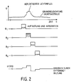
- the latter controls the transmission pulse, the gate pulse and the transfer function - as illustrated in FIG. 2 - in such a way that the entire distance to be considered is scanned by a number of gate pulses which are shifted in time, for example ⁇ 1 to ⁇ 4.
- the charge accumulated on the sensor during the gate pulse is first stored in a CCD memory cell 16a-16n, and the accumulated one on the next gate pulse Charge first inverted and released into the same memory cell, which subtracts both charges.
- a sequential scanning results in a video image in the CCD addition memory 16, as is the case as an example is shown in Fig. 2 and shows the differentiated, reflected light pulse.
- the signal of several pixels thus transformed in its time unit by the gate clock is combined to form a distance image.
- the contrast image 17a recorded and formed by the controlled inverter 15 is entered directly and then inverted into the CCD addition memory 16 for subtraction and storage of the residual value and is formed there for the distance image 17b.
- the CCD array 13 is composed, for example, of a matrix of 100 ⁇ 100 sensor areas 13a-13n, each area of which is occupied by a sensor cell to which a transfer stage 15a-15n and a charge storage device 16a-16n are assigned.
- This matrix formed in this way can be monolithically integrated on a chip. It is now possible to carry out a sequential subtraction of the incident energy at time "t".
- the shutter 12 controls the sensor 100 for a short gate time - for example 10 nsec sensitive and with an illumination pulse length of e.g. 10 to 100 nsec.
- a real distance image sensor is now created, which provides a relief-like distance image for determining the distances between a vehicle and obstacles etc.
Landscapes
- Engineering & Computer Science (AREA)
- Physics & Mathematics (AREA)
- Computer Networks & Wireless Communication (AREA)
- General Physics & Mathematics (AREA)
- Radar, Positioning & Navigation (AREA)
- Remote Sensing (AREA)
- Electromagnetism (AREA)
- Measurement Of Optical Distance (AREA)
- Optical Radar Systems And Details Thereof (AREA)
- Solid State Image Pick-Up Elements (AREA)
Applications Claiming Priority (2)
| Application Number | Priority Date | Filing Date | Title |
|---|---|---|---|
| DE3732347A DE3732347C1 (de) | 1987-09-25 | 1987-09-25 | Entfernungsbild-Sensor |
| DE3732347 | 1987-09-25 |
Publications (3)
| Publication Number | Publication Date |
|---|---|
| EP0309927A2 true EP0309927A2 (fr) | 1989-04-05 |
| EP0309927A3 EP0309927A3 (en) | 1990-12-27 |
| EP0309927B1 EP0309927B1 (fr) | 1994-03-30 |
Family
ID=6336874
Family Applications (1)
| Application Number | Title | Priority Date | Filing Date |
|---|---|---|---|
| EP88115625A Expired - Lifetime EP0309927B1 (fr) | 1987-09-25 | 1988-09-23 | Détecteur pour image à distance |
Country Status (2)
| Country | Link |
|---|---|
| EP (1) | EP0309927B1 (fr) |
| DE (1) | DE3732347C1 (fr) |
Cited By (5)
| Publication number | Priority date | Publication date | Assignee | Title |
|---|---|---|---|---|
| US5005085A (en) * | 1988-11-23 | 1991-04-02 | Messerschmitt-Boelkow-Blohm Gmbh | Controllable semiconductor image sensor and arrangement with such a sensor |
| WO1996035963A1 (fr) * | 1996-06-04 | 1996-11-14 | Yalestown Corporation N.V. | Dispositif d'observation d'objets |
| DE19719749A1 (de) * | 1997-05-14 | 1998-01-08 | Josef Koelbl | Pikosekunden Laserpuls Diskriminator mit Hilfe eines elektronischen Integrators |
| WO2001000459A1 (fr) * | 1999-06-24 | 2001-01-04 | Fraunhofer-Gesellschaft zur Förderung der angewandten Forschung e.V. | Dispositif et procede de surveillance de siege a l'aide d'une technique de triangulation optoelectronique |
| FR2995699A1 (fr) * | 2012-09-20 | 2014-03-21 | Mbda France | Ecartometre a imagerie infrarouge et systeme de visee et de poursuite automatique de cible |
Families Citing this family (9)
| Publication number | Priority date | Publication date | Assignee | Title |
|---|---|---|---|---|
| DE3942770A1 (de) * | 1989-12-23 | 1991-07-11 | Dornier Luftfahrt | Entfernungsbildkamera |
| DE4305011C2 (de) * | 1993-02-18 | 1995-03-23 | Deutsche Aerospace | Pulslaufzeit-Meßverfahren |
| DE19757595C2 (de) * | 1997-12-23 | 2000-05-11 | Siemens Ag | Verfahren und Vorrichtung zur Aufnahme eines dreidimensionalen Abstandsbildes |
| DE19833207A1 (de) * | 1998-07-23 | 2000-02-17 | Siemens Ag | Verfahren und Vorrichtung zur Aufnahme eines dreidimensionalen Abstandsbildes |
| DE10025258A1 (de) * | 2000-05-22 | 2001-12-06 | Adc Automotive Dist Control | Optisches System |
| DE10124160B4 (de) * | 2001-05-17 | 2006-04-06 | Sick Ag | Verfahren zur Erzeugung eines entfernungsauflösenden Bildes und optoelektronischer Sensor |
| DE10223136C1 (de) * | 2002-05-24 | 2003-12-24 | Fraunhofer Ges Forschung | Verfahren zur Anpassung und Einstellung des Tiefenmessbereichs einer Studiokamera |
| DE102008025825B4 (de) * | 2008-05-29 | 2014-05-22 | Eads Deutschland Gmbh | Verfahren zur hochgenauen Distanzmessung |
| DE102011081384B4 (de) * | 2011-08-23 | 2017-05-04 | Robert Bosch Gmbh | Verfahren und Vorrichtung zur Abstandsbestimmung für ein Fahrzeug |
Family Cites Families (7)
| Publication number | Priority date | Publication date | Assignee | Title |
|---|---|---|---|---|
| US3134975A (en) * | 1960-12-30 | 1964-05-26 | David M Goodman | Radar display for collision warning device and navigational aid |
| DE3020996C2 (de) * | 1980-06-03 | 1989-07-20 | Messerschmitt-Bölkow-Blohm GmbH, 8012 Ottobrunn | Einrichtung zur Bestimmung der Auslöseentfernung von einem sich auf ein Ziel zu bewegenden Flugkörper |
| GB2122833B (en) * | 1982-06-24 | 1985-06-26 | Ferranti Plc | Radiation detecting apparatus |
| DE3404396A1 (de) * | 1984-02-08 | 1985-08-14 | Dornier Gmbh, 7990 Friedrichshafen | Vorrichtung und verfahren zur aufnahme von entfernungsbildern |
| US4727259A (en) * | 1986-02-24 | 1988-02-23 | The United States Of America As Represented By The Secretary Of The Air Force | Monolithic area array with shutter operable to only transmit light between the minimum and maximum ranges for laser rangefinding |
| DE3631373A1 (de) * | 1986-09-15 | 1988-03-24 | Morander Karl Erik | Geraet zur bestimmung des realen oder virtuellen abstandes einer lichtquelle von einer messebene |
| DE3640189C1 (en) * | 1986-11-25 | 1987-09-24 | Messerschmitt Boelkow Blohm | Device for determining the time interval between repetitive events and signals triggered by these events |
-
1987
- 1987-09-25 DE DE3732347A patent/DE3732347C1/de not_active Expired
-
1988
- 1988-09-23 EP EP88115625A patent/EP0309927B1/fr not_active Expired - Lifetime
Cited By (9)
| Publication number | Priority date | Publication date | Assignee | Title |
|---|---|---|---|---|
| US5005085A (en) * | 1988-11-23 | 1991-04-02 | Messerschmitt-Boelkow-Blohm Gmbh | Controllable semiconductor image sensor and arrangement with such a sensor |
| WO1996035963A1 (fr) * | 1996-06-04 | 1996-11-14 | Yalestown Corporation N.V. | Dispositif d'observation d'objets |
| DE19719749A1 (de) * | 1997-05-14 | 1998-01-08 | Josef Koelbl | Pikosekunden Laserpuls Diskriminator mit Hilfe eines elektronischen Integrators |
| WO2001000459A1 (fr) * | 1999-06-24 | 2001-01-04 | Fraunhofer-Gesellschaft zur Förderung der angewandten Forschung e.V. | Dispositif et procede de surveillance de siege a l'aide d'une technique de triangulation optoelectronique |
| US6678598B1 (en) | 1999-06-24 | 2004-01-13 | Fraunhofer-Gesellschaft Zur Foerderung Der Angewandten Forschung E.V. | Device and method for seat supervision in motor vehicles |
| FR2995699A1 (fr) * | 2012-09-20 | 2014-03-21 | Mbda France | Ecartometre a imagerie infrarouge et systeme de visee et de poursuite automatique de cible |
| EP2711732A1 (fr) * | 2012-09-20 | 2014-03-26 | MBDA France | Ecartomètre à imagerie infrarouge et système de visée et de poursuite automatique de cible |
| WO2014044928A1 (fr) * | 2012-09-20 | 2014-03-27 | Mbda France | Ecartomètre à imagerie infrarouge et système de visée et de poursuite automatigue de cible |
| US9367741B2 (en) | 2012-09-20 | 2016-06-14 | Mbda France | Deviation indicator with infrared imagery and system for automatically aiming at and tracking a target |
Also Published As
| Publication number | Publication date |
|---|---|
| EP0309927B1 (fr) | 1994-03-30 |
| DE3732347C1 (de) | 1989-03-16 |
| EP0309927A3 (en) | 1990-12-27 |
Similar Documents
| Publication | Publication Date | Title |
|---|---|---|
| DE69222083T2 (de) | Verfahren zum Detektieren von vor einem Kraftzeug befindlichen Hindernissen, und Gerät zum Ausführen des Verfahrens | |
| EP0151257B1 (fr) | Procédé pour la production d'images codées en distance | |
| EP0309927A2 (fr) | Détecteur pour image à distance | |
| DE3942770C2 (fr) | ||
| DE60124647T2 (de) | Vorrichtung und Verfahren zur Abstandsmessung | |
| DE3404166C2 (de) | Verfahren zur Konturerkennung von völlig oder teilweise durchsichtigen Gegenständen und Vorrichtung zur Durchführung des Verfahrens | |
| DE3640449C1 (de) | Einrichtung zum Bestimmen der Entfernung zwischen zwei Objekten,insbesondere zwei Kraftfahrzeugen | |
| DE2941194A1 (de) | Vielkanaliges digitales seismisches system zum ansammeln von signalen fuer den feldgebrauch | |
| DE3688341T2 (de) | Videokamera. | |
| DE3020996C2 (de) | Einrichtung zur Bestimmung der Auslöseentfernung von einem sich auf ein Ziel zu bewegenden Flugkörper | |
| DE19645175A1 (de) | Verfahren zum Steuern einer optischen Überwachungseinrichtung | |
| EP0531722A2 (fr) | Procédé et appareil pour enregistrer images en fonction de la distance | |
| DE2739348A1 (de) | Anordnung zur messung der hoehe von wolken | |
| DE3844654C2 (fr) | ||
| DE3539713A1 (de) | Bildleseeinrichtung | |
| DE68912154T2 (de) | Optisches Standortbestimmungs- und -messsystem für Raumfahrzeuge. | |
| DE2528402A1 (de) | Passiver ir-abstandszuender | |
| DE3411690A1 (de) | Fotoelektrische wandlervorrichtung | |
| DE2945825A1 (de) | Verfahren und vorrichtung zur strahlablenkung fuer ultraschall-abbildungssysteme mit sektorabtastung | |
| DE2800195A1 (de) | Anlage zur automatischen verhuetung von schiffskollisionen | |
| DE2106035A1 (de) | Vorr-chtung zum automatischen Verfolgen und Erkennen von Bildkontrasten | |
| CH616508A5 (fr) | ||
| DE3110828C2 (de) | Verfahren und Anordnung zur Erzeugung von miteinander zu korrelierenden Signalen, insbesondere zur berührungslosen Geschwindigkeitsmessung | |
| DE112021003845T5 (de) | Datenverarbeitungsvorrichtung, Datenverarbeitungssystem, Datenverarbeitungsverfahren und Datenverarbeitungsprogramm technisches Gebiet | |
| DE2845164A1 (de) | Ziel-ortungs- und entfernungs- messystem |
Legal Events
| Date | Code | Title | Description |
|---|---|---|---|
| PUAI | Public reference made under article 153(3) epc to a published international application that has entered the european phase |
Free format text: ORIGINAL CODE: 0009012 |
|
| AK | Designated contracting states |
Kind code of ref document: A2 Designated state(s): FR GB IT SE |
|
| PUAL | Search report despatched |
Free format text: ORIGINAL CODE: 0009013 |
|
| AK | Designated contracting states |
Kind code of ref document: A3 Designated state(s): FR GB IT SE |
|
| 17P | Request for examination filed |
Effective date: 19901122 |
|
| RAP1 | Party data changed (applicant data changed or rights of an application transferred) |
Owner name: DEUTSCHE AEROSPACE AKTIENGESELLSCHAFT |
|
| 17Q | First examination report despatched |
Effective date: 19930219 |
|
| GRAA | (expected) grant |
Free format text: ORIGINAL CODE: 0009210 |
|
| AK | Designated contracting states |
Kind code of ref document: B1 Designated state(s): FR GB IT SE |
|
| ET | Fr: translation filed | ||
| GBT | Gb: translation of ep patent filed (gb section 77(6)(a)/1977) |
Effective date: 19940429 |
|
| ITF | It: translation for a ep patent filed | ||
| RAP2 | Party data changed (patent owner data changed or rights of a patent transferred) |
Owner name: TEMIC TELEFUNKEN MICROELECTRONIC GMBH |
|
| REG | Reference to a national code |
Ref country code: GB Ref legal event code: 732E |
|
| REG | Reference to a national code |
Ref country code: FR Ref legal event code: TP |
|
| EAL | Se: european patent in force in sweden |
Ref document number: 88115625.1 |
|
| PLBE | No opposition filed within time limit |
Free format text: ORIGINAL CODE: 0009261 |
|
| STAA | Information on the status of an ep patent application or granted ep patent |
Free format text: STATUS: NO OPPOSITION FILED WITHIN TIME LIMIT |
|
| 26N | No opposition filed | ||
| REG | Reference to a national code |
Ref country code: GB Ref legal event code: IF02 |
|
| PGFP | Annual fee paid to national office [announced via postgrant information from national office to epo] |
Ref country code: FR Payment date: 20050823 Year of fee payment: 18 |
|
| PGFP | Annual fee paid to national office [announced via postgrant information from national office to epo] |
Ref country code: GB Payment date: 20050912 Year of fee payment: 18 |
|
| PGFP | Annual fee paid to national office [announced via postgrant information from national office to epo] |
Ref country code: SE Payment date: 20050914 Year of fee payment: 18 |
|
| PG25 | Lapsed in a contracting state [announced via postgrant information from national office to epo] |
Ref country code: SE Free format text: LAPSE BECAUSE OF NON-PAYMENT OF DUE FEES Effective date: 20060924 |
|
| PGFP | Annual fee paid to national office [announced via postgrant information from national office to epo] |
Ref country code: IT Payment date: 20060930 Year of fee payment: 19 |
|
| EUG | Se: european patent has lapsed | ||
| GBPC | Gb: european patent ceased through non-payment of renewal fee |
Effective date: 20060923 |
|
| REG | Reference to a national code |
Ref country code: FR Ref legal event code: ST Effective date: 20070531 |
|
| PG25 | Lapsed in a contracting state [announced via postgrant information from national office to epo] |
Ref country code: GB Free format text: LAPSE BECAUSE OF NON-PAYMENT OF DUE FEES Effective date: 20060923 |
|
| PG25 | Lapsed in a contracting state [announced via postgrant information from national office to epo] |
Ref country code: FR Free format text: LAPSE BECAUSE OF NON-PAYMENT OF DUE FEES Effective date: 20061002 |
|
| PG25 | Lapsed in a contracting state [announced via postgrant information from national office to epo] |
Ref country code: IT Free format text: LAPSE BECAUSE OF NON-PAYMENT OF DUE FEES Effective date: 20070923 |