EP0309936B1 - Presse à balles rondes avec dispositif anti-engorgement - Google Patents
Presse à balles rondes avec dispositif anti-engorgement Download PDFInfo
- Publication number
- EP0309936B1 EP0309936B1 EP88115664A EP88115664A EP0309936B1 EP 0309936 B1 EP0309936 B1 EP 0309936B1 EP 88115664 A EP88115664 A EP 88115664A EP 88115664 A EP88115664 A EP 88115664A EP 0309936 B1 EP0309936 B1 EP 0309936B1
- Authority
- EP
- European Patent Office
- Prior art keywords
- roller
- bale
- roll
- flap
- periphery
- Prior art date
- Legal status (The legal status is an assumption and is not a legal conclusion. Google has not performed a legal analysis and makes no representation as to the accuracy of the status listed.)
- Expired
Links
Images
Classifications
-
- A—HUMAN NECESSITIES
- A01—AGRICULTURE; FORESTRY; ANIMAL HUSBANDRY; HUNTING; TRAPPING; FISHING
- A01F—PROCESSING OF HARVESTED PRODUCE; HAY OR STRAW PRESSES; DEVICES FOR STORING AGRICULTURAL OR HORTICULTURAL PRODUCE
- A01F15/00—Baling presses for straw, hay or the like
- A01F15/07—Rotobalers, i.e. machines for forming cylindrical bales by winding and pressing
-
- A—HUMAN NECESSITIES
- A01—AGRICULTURE; FORESTRY; ANIMAL HUSBANDRY; HUNTING; TRAPPING; FISHING
- A01F—PROCESSING OF HARVESTED PRODUCE; HAY OR STRAW PRESSES; DEVICES FOR STORING AGRICULTURAL OR HORTICULTURAL PRODUCE
- A01F15/00—Baling presses for straw, hay or the like
- A01F15/07—Rotobalers, i.e. machines for forming cylindrical bales by winding and pressing
- A01F2015/078—Pressing chamber formed exclusively by flexible elements, e.g. belts
-
- A—HUMAN NECESSITIES
- A01—AGRICULTURE; FORESTRY; ANIMAL HUSBANDRY; HUNTING; TRAPPING; FISHING
- A01F—PROCESSING OF HARVESTED PRODUCE; HAY OR STRAW PRESSES; DEVICES FOR STORING AGRICULTURAL OR HORTICULTURAL PRODUCE
- A01F15/00—Baling presses for straw, hay or the like
- A01F15/07—Rotobalers, i.e. machines for forming cylindrical bales by winding and pressing
- A01F2015/0795—Pressing chamber with variable volume
-
- A—HUMAN NECESSITIES
- A01—AGRICULTURE; FORESTRY; ANIMAL HUSBANDRY; HUNTING; TRAPPING; FISHING
- A01F—PROCESSING OF HARVESTED PRODUCE; HAY OR STRAW PRESSES; DEVICES FOR STORING AGRICULTURAL OR HORTICULTURAL PRODUCE
- A01F15/00—Baling presses for straw, hay or the like
- A01F15/08—Details
- A01F15/18—Endless belts, rolls or the like
- A01F2015/186—Constructional details of rollers or the bearings of the rollers of the press chamber
Definitions
- This invention relates to a rotary crop baler according to the preamble of claim 1.
- balers have been developed which incorporate a support roll adjacent the bottom of the baling chamber for keeping the bale from riding against a web of belts wrapped around a forward roll.
- Such support rolls have either been smooth, or as disclosed in US-A-4 182 101, have had rigid undulations along the length thereof.
- crop material often tends to be sloughed off the bale and driven between the support roll and the forward roll by an aggressively driven downward stretch of web. Accumulation of crop material in this zone between the rollers can lead to binding therebetween creating substantial frictional forces and either damaging the belts of effectively shutting down the machine.
- the purpose of the invention is to provide an improved baler in which accumulations of crop material in undesired locations are avoided. According to the invention this purpose is attained by a baler having the features defined in the characterising portion of claim 1.
- the bale supporting roller rotates, moving its flaps through the zone between the support roller and the forward roll, thereby ejecting crop materials from the zone and back into the baling chamber.
- the flaps extend across the zone and wipe the web passing between the roll and the roller.
- the outwardly extending flaps engage the periphery of the bale, yielding thereto and conforming with the periphery of the shaft so as to provide a substantially circular, smoothly curved, gentle roller surface for supporting the periphery of the bale without damage thereto.
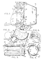
- the baler 10 has a pair of laterally spaced-apart sidewalls 12 (only one being shown) that cooperate to provide the lateral extremities of a bale forming chamber denoted broadly by the numeral 14.
- the sidewalls 12 are carried on a suitable chasis which is in turn carried by a pair of ground wheels 16 located on opposite sides of the bale 10 outboard of the respective sidewalls 12.
- a fore-and-aft extending tongue 18 located adjacent the front end of the baler 10 relative to its normal direction of travel adapts the same to be hitched behind a towing tractor or the like for advancement across a field having windrowed crop material deposited thereon.
- a pickup 20 spaced rearwardly from the front extremity of the sidewalls 12 and located substantially directly beneath the chamber 14 is operable to pick up windrowed material from the field as the baler 10 passes over the same and to feed such material up into the chamber 14 through an entrance 22 defined between transversely extending forward roll 24 and shaft 26 spanning the sidewalls 12 and located in fore-and-aft spaced relationship to one another.
- An anti-plugging roller 28 spanning sidewalls 12 and situated rearwardly adjacent the front roll 24 keeps the bale off roll 24 during formation.
- shafts 30 are all idler shafts, while the roll 24 is rotatively driven in a clockwise direction viewing Figs. 1 and 2 by belt and pulley mechanism 29 illustrated in Fig. 5.
- the bale chamber 14 is further defined by structure in the form of an endless, flexible web broadly denoted by the numeral 31 which is looped over and under the various shafts in such a manner as to present a pair of generally upright, opposed web stretches 32 and 34 which initially move in opposite, generally vertical directions, stretch 32 moving upwardly and stretch 34 moving downwardly.
- the web stretches 32, 34 are held apart at their lower ends by the roll 24 and the shaft 26 such as to present the entrance 22, and the stretches 32, 34 are held close together at a location above the entrance 22 by a retaining device 36 in the nature of a pair of elongated, fore-and-aft spaced-apart shafts 38, 40 extending laterally across the width of the baler and rotatively mounted on and extending laterally between a pair of arms 42 (only one being shown).
- the pair of arms 42 are attached to respective sidewalls 12 and are pivotally mounted onto the sidewalls along a common pivot axis 44 and are biased downwardly about that axis 44 by a mechanism not shown but readily understood by those skilled in the art.
- a tensioning device 46 maintains the web taut during bale formation and includes a pair of shafts 48 having web 31 looped thereunder.
- the shafts 48 are spaced fore-and-aft and are rotatably mounted between a pair of laterally spaced-apart tensioning arms 50 which are mounted to respective sidewalls 12 along aligned pivots 52 (only one being shown) and are biased downward, as viewed in Figure 1, for maintaining the web taut.
- the web 31 preferably takes the form of a series of endless, identical belts 54 spaced a short distance apart across the baler 10 and between the sidewalls 12.
- the anti-plugging roller 28 is located within entrance 22 adjacent roll 24 and spaced slightly rearwardly and below roll 24. As shown in Fig. 2, roller 28 supports the lower periphery of a bale 56 during formation thereof. Roller 28 includes a shaft 58 rotatably mounted on and extending laterally between sidewalls 12. Web stretch 34 passes between roller 28 and roll 24 and is aggressively driven downwardly by roll 24 thus forcibly rotating the forming bale 56 and sometimes carrying crop materials into a zone 60 generally located between roll 24 and roller 28.
- elongated ribs 62 are affixed to the periphery of the shaft 58 along the length thereof and are equally spaced about the circumference of the shaft 58.
- elongated, resilient, anti-plugging flaps 64 extend along the length of shaft 58 and are mounted at their leading edges 66 directly behind respective ribs 62. Each leading edge 66 is overlapped by a narrow, metallic support strip 68 which receives screws 70 that extend through the flap 62 and thread into an outer tubular wall 72 of shaft 58. Once the screws 66 are tightly screwed into the shaft 58, screw heads 74 bear against each strip 68 thereby holding flaps 64 firmly against the shaft 58 and effectively preventing the flaps 64 from tearing away from the screws 70.
- the somewhat stiff yet resilient nature of the flaps 64 permits them to normally extend tangentially outward from the periphery of the shaft 58 while at the same time permitting the flaps 64 to be forced by the bale during support thereof into a curved shaped conforming with the circumference of the shaft 58. As illustrated in Fig. 2, the flaps 64 normally extend sufficiently far enough away from the periphery of the shaft 58 so as to extend across the zone 60 and engage the web stretch 34 adjacent the roll 24.
- the rubber belt material commonly used by farm equipment manufacturers in connection with the forming belts on their round balers is quite suitable as a material from which the flaps 64 can be made.
- This corresponds to the belt material used in connection with the web 31 on the baler 10 of the present invention.
- the material used for the flaps 64 has an aggressive surface contour presented by ribs in a chevron pattern or otherwise arranged to provide irregularities on the contour.
- the belting material from which the flaps 64 are preferably made is well known to those skilled in the art and is readily available from a variety of commercial sources.
- the components of the baler 10 are disposed in the condition illustrated by Fig. 1.
- the retaining device 36 is in its closest position to the lower shafts so as to maintain the chamber at its smallest size.
- pick-up 20 lifts the materials off the ground and feeds it through the entrance 22 into the chamber 14 whereupon it is acted upon the by oppositely moving, generally vertically directed belt stretches 32, 34 so as to cause the introduced material to tumble forwardly.
- the tumbling material begins to coil up into a bale and exert radially outwardly directed forces against the belt stretches 32, 34 and against the shafts 38, 40 of retaining device 36.
- the outward movement of the belt stretches 32, 34 and upward movement of the retaining device 36 is, of course, resisted by the tension springs (not shown) which bias the arm 42 downwardly about pivot axis 44.
- bale 56 As the bale 56 begins to form, it rotates in a generally counterclockwise direction viewing Fig. 2 and is supported by anti-plugging roller 28 which is driven in a clockwise direction by a drive belt and pulley mechanism 76 (illustrated in phantom Fig. 5) which takes power from driven roll 24.
- Roll 24 is driven in a clockwise direction as illustrated in Fig. 2, thereby driving the web 30, and more particularly, driving the web stretch 34 aggressively downwardly between the roll 24 and the roller 28.
- the web stretch 34 As the web stretch 34 travels from the baling chamber 14 into zone 60 it tends to carry crop materials with it.
- anti-plugging roller 28 prevents the zone 60 from being plugged with crop material by employing the flaps 64 which, during rotation of the roller 28, pass upwardly through the zone, wiping the stretch 34 adjacent the roll 24 free of crop materials, and forcing crop materials from zone 60 back into baling chamber 14.
- flaps 64 yield slightly, thus preventing substantial wear between the flaps and the web.
- the roller 28 supports the bale 56 and rotates therewith, bringing the ribs 62, the strips 68, and the flaps 64 into supportive engagement with the underside of the bale 56.
- the bale rides on top of the ribs 62 and support strips and is supported thereby.
- the weight of the bale forces the resilient flap 64 to bend until the flap 64 conforms with the curvature of the circumference of the shaft 58.
- the entire width of the flap 64 is then supported by the periphery of the shaft 58 thereby forming a substantially continuous, circular surface of engagement, for supporting the bale 56 without disturbance of the bale periphery while at the same time providing projections which extend outwardly from the shaft 58 for clearing the zone 60 of crop materials, thereby preventing plugging of the zone 60 and binding of the web 31 between the roll 24 and the roller 28.
Landscapes
- Life Sciences & Earth Sciences (AREA)
- Environmental Sciences (AREA)
- Storage Of Harvested Produce (AREA)
Claims (7)
- Presse à balles destinée à former de grosses balles circulaires (56) d'une matière fibreuse de récolte, dans laquelle la presse a une chambre (14) de formation de balle ayant une entrée (22) délimitée par un rouleau transversal supérieur (24) et un rouleau transversal inférieur (26), et un brin (34) de nappe formant une boucle sous le rouleau transversal supérieur (24), le brin de nappe étant normalement au contact de la périphérie de la balle (56) pendant l'enroulement de celle-ci et étant entraîné dans un sens tel que le brin (34) se déplace de façon générale de la balle vers le rouleau (24), un rouleau (28) de support de balle adjacent au côté du rouleau (24) qui reçoit le brin (34) de la balle (56) et ayant une position telle qu'il est au contact de la périphérie inférieure de la balle (56) qui roule et supporte le poids de la balle autrement supporté par le rouleau supérieur (24) et le brin (34) de nappe lorsqu'il se déplace autour du rouleau supérieur (24), le rouleau de support (28) ayant un arbre (58) disposé sur toute la largeur de la machine parallèlement au rouleau supérieur (24) et monté afin qu'il tourne autour de son axe longitudinal, un dispositif destiné à faire tourner le rouleau de support (28) dans le même sens que le rouleau supérieur, le rouleau supérieur (24) et le rouleau de support (28) étant distants et délimitant de façon générale une zone entre eux, caractérisée en ce que le rouleau (28) de support de balle comporte au moins un volet élastique (64) dépassant vers l'extérieur de l'arbre (58) du rouleau et sur la longueur de celui-ci, le volet (64) passant dans ladite zone lorsque le rouleau de support (28) tourne et retire les matières de récolte de ladite zone, le volet élastique (64) fléchissant sous l'action de la balle (56) lorsqu'il est mis au contact de la balle (56) pendant la rotation du rouleau de support (28).
- Presse à balles selon la revendication 1, caractérisée en ce que l'arbre (58) du rouleau de support a une forme générale cylindrique et le volet (64) est disposé de façon générale tangentiellement vers l'extérieur depuis la périphérie de l'arbre (58) et en sens opposé au sens de rotation du rouleau de support (28).
- Presse à balles selon la revendication 2, caractérisée en ce que le rouleau de support comporte en outre une nervure (62) placée sur la longueur de l'arbre (58) et fixée à sa périphérie, le volet (64) étant placé juste derrière la nervure (62), la nervure (62) assurant une protection structurelle du volet (64) pendant la rotation du rouleau de support (28).
- Presse à balles selon la revendication 3, caractérisée en ce que le rouleau de support (28) comporte plusieurs volets (64) et des nervures protectrices correspondantes (62), les nervures (62) étant espacées circonférentiellement à la périphérie du rouleau de support (28).
- Presse à balles selon la revendication 4, caractérisée en ce que les nervures (62) sont régulièrement espacées à la périphérie du rouleau de support (28).
- Presse à balles selon la revendication 1, caractérisée en ce que le volet (64) est disposé afin qu'il soit au contact de la nappe (34) lorsque le volet (64) passe dans ladite zone.
- Presse à balles selon la revendication 2, caractérisée en ce que le volet (64) est suffisamment élastique pour qu'il prenne la forme de la périphérie de l'arbre (58) et délimite une surface circulaire régulière de façon générale pour le rouleau de support pendant le support de la balle (56).
Applications Claiming Priority (2)
| Application Number | Priority Date | Filing Date | Title |
|---|---|---|---|
| US102099 | 1987-09-29 | ||
| US07/102,099 US4782652A (en) | 1987-09-29 | 1987-09-29 | Round baler having anti-plugging means |
Publications (2)
| Publication Number | Publication Date |
|---|---|
| EP0309936A1 EP0309936A1 (fr) | 1989-04-05 |
| EP0309936B1 true EP0309936B1 (fr) | 1991-10-23 |
Family
ID=22288117
Family Applications (1)
| Application Number | Title | Priority Date | Filing Date |
|---|---|---|---|
| EP88115664A Expired EP0309936B1 (fr) | 1987-09-29 | 1988-09-23 | Presse à balles rondes avec dispositif anti-engorgement |
Country Status (4)
| Country | Link |
|---|---|
| US (1) | US4782652A (fr) |
| EP (1) | EP0309936B1 (fr) |
| CA (1) | CA1309293C (fr) |
| DE (2) | DE3865799D1 (fr) |
Cited By (3)
| Publication number | Priority date | Publication date | Assignee | Title |
|---|---|---|---|---|
| EP0462484A3 (en) * | 1990-06-18 | 1992-03-18 | Deere & Company | Balling press to form cylindrical balls of crop |
| EP1588604A1 (fr) | 2004-04-23 | 2005-10-26 | Deere & Company | Presse à balles rondes |
| EP1588603A1 (fr) | 2004-04-23 | 2005-10-26 | Deere & Company | Presse à balles rondes |
Families Citing this family (20)
| Publication number | Priority date | Publication date | Assignee | Title |
|---|---|---|---|---|
| GB2233930A (en) * | 1989-06-28 | 1991-01-23 | Deere & Co | Shield device for baling machine |
| US5165332A (en) * | 1990-01-11 | 1992-11-24 | Gehl Company | Bale density monitoring apparatus and method |
| US5138942A (en) * | 1991-01-28 | 1992-08-18 | Gehl Company | Belt type round baler with adjustable bale starting chamber |
| US5228280A (en) * | 1991-12-20 | 1993-07-20 | Hay & Forage Industries | Round baler having anti-wrapping core starter |
| US5301495A (en) * | 1992-03-12 | 1994-04-12 | Vermeer Manufacturing Company | Unidirectional drum roller for a baler of large cylindrical bales |
| DE4308646C2 (de) * | 1993-03-18 | 2000-01-27 | Claas Ohg | Erntegut-Rundballenformmaschine |
| US5709143A (en) * | 1995-11-21 | 1998-01-20 | Hay & Forage Industries | Round baler twine cutter |
| US5802825A (en) * | 1996-06-03 | 1998-09-08 | New Holland North America, Inc. | Method and apparatus for controlling round bale cutter |
| US5931089A (en) * | 1997-03-07 | 1999-08-03 | Gehl Company | Bale starting chamber with tensioning device |
| US6098391A (en) * | 1998-05-08 | 2000-08-08 | New Holland North America, Inc. | Round bale forming apparatus |
| US6134868A (en) * | 1999-01-07 | 2000-10-24 | Inforcer, Inc. | Baler plug removing system |
| US6655121B1 (en) | 2000-08-10 | 2003-12-02 | Gehl Company | Powered feed roller system for a round baler |
| EP1588605B1 (fr) | 2004-04-23 | 2017-05-03 | Deere & Company | Presse à balles rondes |
| US7841852B2 (en) * | 2005-12-30 | 2010-11-30 | Owens-Corning Fiberglas Technology, Inc. | Apparatus for demolding building products from a mold |
| US8206205B2 (en) * | 2009-05-12 | 2012-06-26 | Deere & Company | Method of unplugging control for a feeding system |
| EP3003008B1 (fr) * | 2013-05-30 | 2021-01-27 | CNH Industrial Belgium N.V. | Articulation d'éjection de balles et procédés d'utilisation |
| GB2529381A (en) * | 2014-06-20 | 2016-02-24 | Kuhn Geldrop Bv | Baler apparatus |
| US9510511B2 (en) * | 2015-04-16 | 2016-12-06 | Deere & Company | Rotary brush for cleaning round module builder belts |
| US11419271B2 (en) | 2020-01-13 | 2022-08-23 | Cnh Industrial America Llc | Agricultural baler with independent tensioning arms |
| GB2614888B (en) * | 2022-01-20 | 2024-04-17 | Kuhn Geldrop Bv | Baler |
Family Cites Families (7)
| Publication number | Priority date | Publication date | Assignee | Title |
|---|---|---|---|---|
| US172354A (en) * | 1876-01-18 | Improvement in whiffletrees | ||
| US4172354A (en) * | 1977-01-28 | 1979-10-30 | Vermeer Manufacturing Company | Machine for forming large round bales of crop material |
| US4182101A (en) * | 1977-12-01 | 1980-01-08 | Hesston Corporation | Machine for coiling fibrous crop materials into large round bales |
| US4224867A (en) * | 1979-03-21 | 1980-09-30 | Hesston Corporation | Crop loading monitor for rotary balers |
| FR2460099A1 (fr) * | 1979-07-04 | 1981-01-23 | Rivierre Casalis Sa | Dispositif d'amenee d'une nappe de fourrage dans une presse a fourrage pour la production de balles roulees |
| DE3468616D1 (en) * | 1984-01-27 | 1988-02-18 | Deere John | Rotobaler with driven bale starter roll |
| US4510741A (en) * | 1984-03-19 | 1985-04-16 | Gehl Company | Rotary crop baler |
-
1987
- 1987-09-29 US US07/102,099 patent/US4782652A/en not_active Expired - Fee Related
-
1988
- 1988-04-18 CA CA000564371A patent/CA1309293C/fr not_active Expired - Fee Related
- 1988-09-23 DE DE8888115664T patent/DE3865799D1/de not_active Expired - Lifetime
- 1988-09-23 DE DE198888115664T patent/DE309936T1/de active Pending
- 1988-09-23 EP EP88115664A patent/EP0309936B1/fr not_active Expired
Cited By (3)
| Publication number | Priority date | Publication date | Assignee | Title |
|---|---|---|---|---|
| EP0462484A3 (en) * | 1990-06-18 | 1992-03-18 | Deere & Company | Balling press to form cylindrical balls of crop |
| EP1588604A1 (fr) | 2004-04-23 | 2005-10-26 | Deere & Company | Presse à balles rondes |
| EP1588603A1 (fr) | 2004-04-23 | 2005-10-26 | Deere & Company | Presse à balles rondes |
Also Published As
| Publication number | Publication date |
|---|---|
| CA1309293C (fr) | 1992-10-27 |
| DE309936T1 (de) | 1990-05-03 |
| US4782652A (en) | 1988-11-08 |
| DE3865799D1 (de) | 1991-11-28 |
| EP0309936A1 (fr) | 1989-04-05 |
Similar Documents
| Publication | Publication Date | Title |
|---|---|---|
| EP0309936B1 (fr) | Presse à balles rondes avec dispositif anti-engorgement | |
| US4581879A (en) | Anti-wrap attachment for rolls of baling machine | |
| US6948300B1 (en) | Wide pickup header for a round baler | |
| US6477824B2 (en) | Round baler having incoming crop deflectors | |
| US4336750A (en) | Stray crop buildup expeller for rotary balers | |
| EP2836062B1 (fr) | Une presse à balles rondes avec un ensemble de bandes | |
| US4273036A (en) | Machine for rolling crops into round bales | |
| US5097760A (en) | Powered trash removal apparatus for round baler | |
| US4406221A (en) | Bale retainer for roll baling machine | |
| US4458587A (en) | Adjustable bale kicker | |
| US4258619A (en) | Rotary baler having bale-ejecting apparatus | |
| US5165333A (en) | Round baler having anti-wrapping idler rolls | |
| US5228280A (en) | Round baler having anti-wrapping core starter | |
| US4436027A (en) | Stripper bar for roll baling machine | |
| US5127217A (en) | Round baler having wide windrow converging mechanism | |
| US5913805A (en) | Trash baffle for round baler apparatus | |
| US5193450A (en) | Residue reducing belt roller construction for round balers | |
| US5080009A (en) | Round baler having trash discharge mechanism | |
| US4926625A (en) | Windrow turning apparatus | |
| US5749289A (en) | Tall sleeves for round baler drive rolls | |
| US3979892A (en) | Machine for forming large round bales | |
| GB2100106A (en) | Straw planter for forming plant-protecting barrier | |
| US5408925A (en) | Trash removal apparatus for a round baler | |
| US4183197A (en) | Machine for forming large round bales | |
| JP2868182B2 (ja) | 根菜類の収穫装置 |
Legal Events
| Date | Code | Title | Description |
|---|---|---|---|
| PUAI | Public reference made under article 153(3) epc to a published international application that has entered the european phase |
Free format text: ORIGINAL CODE: 0009012 |
|
| AK | Designated contracting states |
Kind code of ref document: A1 Designated state(s): BE DE FR GB IT |
|
| 17P | Request for examination filed |
Effective date: 19890923 |
|
| RAP1 | Party data changed (applicant data changed or rights of an application transferred) |
Owner name: HESSTON BRAUD (SOCIETE ANONYME) |
|
| ITCL | It: translation for ep claims filed |
Representative=s name: JACOBACCI CASETTA & PERANI S.P.A. |
|
| EL | Fr: translation of claims filed | ||
| 17Q | First examination report despatched |
Effective date: 19900129 |
|
| DET | De: translation of patent claims | ||
| GRAA | (expected) grant |
Free format text: ORIGINAL CODE: 0009210 |
|
| AK | Designated contracting states |
Kind code of ref document: B1 Designated state(s): BE DE FR GB IT |
|
| ITF | It: translation for a ep patent filed | ||
| REF | Corresponds to: |
Ref document number: 3865799 Country of ref document: DE Date of ref document: 19911128 |
|
| ET | Fr: translation filed | ||
| PLBE | No opposition filed within time limit |
Free format text: ORIGINAL CODE: 0009261 |
|
| STAA | Information on the status of an ep patent application or granted ep patent |
Free format text: STATUS: NO OPPOSITION FILED WITHIN TIME LIMIT |
|
| 26N | No opposition filed | ||
| PGFP | Annual fee paid to national office [announced via postgrant information from national office to epo] |
Ref country code: BE Payment date: 20010710 Year of fee payment: 14 |
|
| REG | Reference to a national code |
Ref country code: GB Ref legal event code: IF02 |
|
| PG25 | Lapsed in a contracting state [announced via postgrant information from national office to epo] |
Ref country code: BE Free format text: LAPSE BECAUSE OF NON-PAYMENT OF DUE FEES Effective date: 20020930 |
|
| BERE | Be: lapsed |
Owner name: S.A. *HESSTON BRAUD Effective date: 20020930 |
|
| REG | Reference to a national code |
Ref country code: GB Ref legal event code: 732E |
|
| REG | Reference to a national code |
Ref country code: FR Ref legal event code: TP Ref country code: FR Ref legal event code: CD |
|
| PGFP | Annual fee paid to national office [announced via postgrant information from national office to epo] |
Ref country code: GB Payment date: 20050624 Year of fee payment: 18 |
|
| PGFP | Annual fee paid to national office [announced via postgrant information from national office to epo] |
Ref country code: FR Payment date: 20050705 Year of fee payment: 18 |
|
| PGFP | Annual fee paid to national office [announced via postgrant information from national office to epo] |
Ref country code: DE Payment date: 20050711 Year of fee payment: 18 |
|
| PG25 | Lapsed in a contracting state [announced via postgrant information from national office to epo] |
Ref country code: IT Free format text: LAPSE BECAUSE OF NON-PAYMENT OF DUE FEES;WARNING: LAPSES OF ITALIAN PATENTS WITH EFFECTIVE DATE BEFORE 2007 MAY HAVE OCCURRED AT ANY TIME BEFORE 2007. THE CORRECT EFFECTIVE DATE MAY BE DIFFERENT FROM THE ONE RECORDED. Effective date: 20050923 |
|
| PG25 | Lapsed in a contracting state [announced via postgrant information from national office to epo] |
Ref country code: DE Free format text: LAPSE BECAUSE OF NON-PAYMENT OF DUE FEES Effective date: 20070403 |
|
| GBPC | Gb: european patent ceased through non-payment of renewal fee |
Effective date: 20060923 |
|
| REG | Reference to a national code |
Ref country code: FR Ref legal event code: ST Effective date: 20070531 |
|
| PG25 | Lapsed in a contracting state [announced via postgrant information from national office to epo] |
Ref country code: GB Free format text: LAPSE BECAUSE OF NON-PAYMENT OF DUE FEES Effective date: 20060923 |
|
| PG25 | Lapsed in a contracting state [announced via postgrant information from national office to epo] |
Ref country code: FR Free format text: LAPSE BECAUSE OF NON-PAYMENT OF DUE FEES Effective date: 20061002 |