EP0309965B1 - Récipient de réception d'aiguilles d'injection usagées - Google Patents
Récipient de réception d'aiguilles d'injection usagées Download PDFInfo
- Publication number
- EP0309965B1 EP0309965B1 EP88115826A EP88115826A EP0309965B1 EP 0309965 B1 EP0309965 B1 EP 0309965B1 EP 88115826 A EP88115826 A EP 88115826A EP 88115826 A EP88115826 A EP 88115826A EP 0309965 B1 EP0309965 B1 EP 0309965B1
- Authority
- EP
- European Patent Office
- Prior art keywords
- case
- movable member
- injection needle
- syringe
- box
- Prior art date
- Legal status (The legal status is an assumption and is not a legal conclusion. Google has not performed a legal analysis and makes no representation as to the accuracy of the status listed.)
- Expired - Lifetime
Links
Images


Classifications
-
- A—HUMAN NECESSITIES
- A61—MEDICAL OR VETERINARY SCIENCE; HYGIENE
- A61M—DEVICES FOR INTRODUCING MEDIA INTO, OR ONTO, THE BODY; DEVICES FOR TRANSDUCING BODY MEDIA OR FOR TAKING MEDIA FROM THE BODY; DEVICES FOR PRODUCING OR ENDING SLEEP OR STUPOR
- A61M5/00—Devices for bringing media into the body in a subcutaneous, intra-vascular or intramuscular way; Accessories therefor, e.g. filling or cleaning devices, arm-rests
- A61M5/178—Syringes
- A61M5/31—Details
- A61M5/32—Needles; Details of needles pertaining to their connection with syringe or hub; Accessories for bringing the needle into, or holding the needle on, the body; Devices for protection of needles
- A61M5/3205—Apparatus for removing or disposing of used needles or syringes, e.g. containers; Means for protection against accidental injuries from used needles
- A61M2005/3208—Apparatus for removing or disposing of used needles or syringes, e.g. containers; Means for protection against accidental injuries from used needles by application of rotational movement to the needle hub, e.g. by use of electrically driven toothed wheels
-
- Y—GENERAL TAGGING OF NEW TECHNOLOGICAL DEVELOPMENTS; GENERAL TAGGING OF CROSS-SECTIONAL TECHNOLOGIES SPANNING OVER SEVERAL SECTIONS OF THE IPC; TECHNICAL SUBJECTS COVERED BY FORMER USPC CROSS-REFERENCE ART COLLECTIONS [XRACs] AND DIGESTS
- Y10—TECHNICAL SUBJECTS COVERED BY FORMER USPC
- Y10T—TECHNICAL SUBJECTS COVERED BY FORMER US CLASSIFICATION
- Y10T29/00—Metal working
- Y10T29/53—Means to assemble or disassemble
- Y10T29/53687—Means to assemble or disassemble by rotation of work part
Definitions
- the present invention relates to a box for disposing of used injection needles, and more particularly to a box for disposing of used injection needles capable of easily and surely removing used injection needles from syringes without injuring fingers and the like, and capable of safely and hygienically discarding used injection needles together with the box.
- the box can be preferably used for containing and discarding screw-type double-edged injection needles (such an injection needle that is fixed to a syringe by means of a screw at its hub and has two needle points at both ends, i.e. on the sides of human body and liquid drug) such as dental injection needles.
- cap a cap or container
- connection screw connection
- a cap sometimes comes off by mere chance although a used injection needle is covered with a cap. Accordingly, there is a danger, when carrying injection needles encased in a bag, that arms or legs of a carrier are injured by injection needles piercing the bag.
- the present invention comprises two embodiments, which have the common object described above and this object can be achieved by the features of claim 1.
- the injection-needle-detaching means provided in the case has a holding portion of which shape fits the shape of a hub of the injection needle.
- the injection needle inserted into the case through an insertion opening made in the case is firmly held by the holding portion, since the size of the opening defined by the holding portion is a little smaller than that of a cross section of the hub and the hub itself has elasticity.
- the rotation of the syringe releases the connection between the syringe and the injection needle.
- the injection needle removed from the syringe remains held by the holding portion, and moves along a notch formed at the fixed member together with the movable member, while contacting with the fixed member, by moving the movable member forming a part of the holding portion against elastic force of the elastic means. Then the injection needle stops contacting with the fixed member and drops into the case.
- the injection needle is unscrewed from the syringe by inserting the syringe into the tubular guide hole, and by manually rotating the syringe anticlockwise while holding a hub of the injection needle with the holding means to prevent the rotation of the hub.
- a push of the operation rod releases the holding condition by the fixed member and movable member, whereby the injection needle held by the holding means drops into the case.
- the injection needle even in the case of double-edged injection needle can smoothly drop into the case without being caught by any portion in the case since a slit is formed at the under surface of the guide hole, so that the removal of the injection needle can be easily carried out.
- the cap at the tip of the operation rod is detached from the rod and inserted into the opening of the guide hole. Then the box can be disposed of safely because the opening of the box is perfectly closed and therefore injection needles in the box never goes out of the box.
- dispenser box a box for disposing of used injection needles (hereafter referred to as "disposing box") of the present invention based on the accompanying drawings.
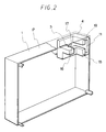
- the disposing box of the first invention is composed of a case 1 and an injection-needle-detaching means (hereafter referred to as "detaching means") arranged in the case 1.
- the detaching means is composed of an elastic means 6, a movable member 3, a rod 7, and a fixed member 4. Each element is explained in detail below.
- the case 1 serves to contain used injection needles removed from syringes.
- the size and shape of the case 1 are not particularly limited in the present invention, the case 1 preferably has size and shape suitable for the holding with one hand when an injection needle is removed from a syringe by the method mentioned later wherein the case 1 is held with one hand and the injection needle is inserted into an insertion opening 2 made in the case 1 with the other hand.
- the handler is often obliged to remove injection needles with only one hand.
- the case 1 is fixed to a suitable position in the room, so that the size and shape thereof might be determined optionally regardless of the size and shape suitable for the holding with one hand described above.
- An opening 2 for the insertion of a used injection needle is made on the upper or side surface of the case 1.
- the position of the insertion opening 2 is not particularly limited and might be made on such a position that the handler can easily insert injection needles.
- the insertion opening 2 is made on the upper surface (shown by symbol P in Figs.1 to 3) of the case 1.
- the size of the insertion opening 2 might be suitably determined in consideration of the thickness of a tip portion of a syringe 20 (see Fig. 5).
- the size of the insertion opening 2 is so determined as to allow the insertion of the syringe 20 to such a position that a hub 22 of the injection needle 21 can be firmly positioned in an opening 12 defined by a movable member 3 and a fixed member 4 and can be held by both members 3,4.
- the case 1 As a material for the case 1, there can be preferably used acrylonitrile-butadiene-styrene copolymer, polypropylene, polyethylene, polycarbonate, polystyrene, polyacetal, polyamide, vinyl chloride resin and the like.
- a transparent or semitransparent case is preferable because of assuring ascertainment of the contained used injection needles from outside the case.
- the case 1 is composed of two or more portions, and is assembled by a suitable combining or connecting method such as heat sealing, ultrasonic sealing and adhering, depending on the material of the case 1 after arranging a movable member 3, elastic means 6, rod 7 and fixed member 4 at prescribed positions in the case 1.
- the case 1 is composed of two portions.
- the disposing box A is completed by combining a portion shown in Fig. 1 and a portion shown in Fig 3.
- a detaching means is arranged in the case 1.
- the functions of the detaching means are to hold the hub 22 of the injection needle 21 inserted through the insertion opening 2, to remove the injection needle 21 from the syringe 20 by a prescribed operation, and to drop the injection needle 21, which is held by the movable member 3 and fixed member 4 in a removed state, into the case 1.
- the detaching means is, as described above, composed of the elastic means 6, movable member 3, rod 7 and fixed member 4 (see Figs. 1 to 4).
- the fixed member 4 positioning the movable member 3 at a prescribed place in the case 1 is fixedly arranged under the insertion opening 2 made in the case 1.
- the fixed member 4 has a holding portion 5 having a shape which corresponds to a part (about one-fourth) of a cross section of the hub 22 as shown in Fig. 2.
- the holding portion 5 cooperates with the other holding portion 9 formed at the movable member 3 to hold the hub 22. Accordingly, the shape of the holding portions 5, 9 varies depending on the cross sectional shape of the hub 22 of the injection needle 21 to be discarded.
- numeral 11 is a guide into which the movable member 3 is inserted.
- the fixed member 4 further has a notch 16 continuing to the holding portion 5.
- the notch 16 serves as a passage of the injection needle 21 when moving the injection needle 21 removed from the syringe 20 together with the movable member 3. As shown in Fig. 1, the notch 16 provides a clearance of about one-half of the diameter of the opening 12 between the movable member 3 and fixed member 4.
- the fixed member 4 is composed of two portions. These two portions are combined by inserting a projection 18 of the fixed member into the corresponding recess 19.
- the movable member 3 has a holding portion 9 of which shape corresponds to a part (about one-half) of a cross sectional shape of the hub 22.
- the hub 22 is firmly held by the holding portion 9 and holding portion 5 formed at the movable member 3 and fixed member 4 respectively.
- the hub 22 is firmly held by the holding portions 5, 9 when the hub 22 is inserted in the opening 12, because the size of the opening 12 is a litle smaller than that of a cross section of the hub 22 and the hub 22 itself has elasticity, i.e. capability of shrinking a little in the radial direction.
- the movable member 3 is within the guide 11 and can move only in the direction parallel to that of elastic force of the elastic means 6. In the specification, "direction of elastic force of the elastic means” is a direction in which the elastic means returns to its original shape.
- the elastic means 6 is fixed to or contacted with an end of the movable member 3.
- the end of a spring (elastic means) is so designed as to fit into a recess 14 formed at the movable member 3.
- the other end of the spring might be fixed to the case 1, or might be put on a projection formed on the inner surface of the case 1.
- the elastic means 6 serves to keep the movable member 3 by its elastic force at such a position that the holding portion 9 of the movable member 3 and holding portion 5 of the fixed member 4 cooperate to form an opening 12 which corresponds to the cross sectional shape of the hub 22.
- a rod 7 for moving the movable member 3 against elastic force of the elastic means 6 is fixed to or contacted with the end opposite to an end of the movable member 3 to which or with which the elastic means 6 is fixed or contacted.
- the term "rod” is a wide conception including bar members, plate members, and the like, and includes any member as long as it functions as a “rod” in the present invention.
- a part of the rod 7 protrudes outside the case 1 through a hole 17 (see Fig. 5) made in the case 1.
- an approximately rectangular pressing plate 10 which is so curved as to fascilitate the pressing operation by a finger.
- the pressing plate 10 can be attached to the end of the rod 7 protruding from the case 1 by means of adhesives or screws.
- the syringe 20 is inserted into the insertion opening 2 made in the case 1 to fit the hub 22 in the opening 12 defined by the holding portion 9 of the movable member 3 and the holding portion 5 of the fixed member 4 (see Fig. 5).
- the syringe 20 is rotated to release the screw connection between the injection needle 21 and syringe 20.
- the pulling out of the syringe 20 from the insertion opening 2 causes the injection needle 21 to be held by the movable member 3 and fixed member 4 and to be remained in the case 1.
- the injection needle 21 is firmly held by the movable member 3 and fixed member 4 mainly due to elasticity of the hub 22 itself.
- the injection needle 21 removed from the syringe 20 and held by the movable member 3 and fixed member 4 can be dropped into and contained in the case 1 by pressing the plate 10 against elastic force of the elastic means 6.
- the attachment of a baffleplate 15 to the fixed member 4 securely causes the injection needle 21 to be dropped into the case. Injection needles are contained in this way, and the box might be discarded when it is filled with used injection needles.
- the disposing box of the present invention can be preferably used in discarding screw-type injection needles, or Lure-lock-type injection needles (i.e. injection needles which enable connection between injection needles and syringes by inserting the injection needles into connecting portions of the syringes and rotating a little in one direction).
- Lure-lock-type injection needles i.e. injection needles which enable connection between injection needles and syringes by inserting the injection needles into connecting portions of the syringes and rotating a little in one direction.
- the disposing box When used in discarding double-edged injection needles or blood-gathering needles among the above injection needles, the disposing box remarkably exhibits its convenience due to the holding effect of the holding portion.
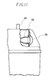
- numerals 31, 32 and 33 are a case, a tubular guide hole and a slit, respectively.
- the case 31 serves to contain used injection needles removed from syringes, and is not particularly limited in its shape and size.
- a tubular guide hole 32 is laterally provided at the upper side wall of the case 31.
- the size of the guide hole 32 is large enough to enable insertion of a tip portion of a syringe, and is tapered down toward the inner part thereof.
- a slit 33 is formed at the under surface of the guide hole 32. The slit 33 has sufficient width and length to allow easy passage of a needle of double-edged injection needle on the side of the liquid drug.
- An operation rod 34 protrudes upwardly from the top surface of the case 31.
- a cap 35 is put on the tip of the operation rod 34.
- a mark 46 showing the rotational direction of a syringe inserted into the guide hole 32 is integrally formed with the guide hole 32.
- the holding means 36 comprises a fixed member 37 and a movable member 38.
- the fixed member 37 is fixed to the case 31 through a bracket 41.
- the movable member 38 can slide up and down within a guide 42 fixed to the case 31.
- the above-mentioned operation rod 34 is integrally formed with the movable member 38.
- a spring 43 is arranged between the bottom surface of the movable member 38 and the guide 42.
- Fig. 7 shows the movable member 38 pressed upwardly by the spring 43.
- Holding portions 44 and 45 are formed respectively at such portions of the fixed member 37 and movable member 38 that face each other in the condition in which the movable member 38 is pressed upwardly.
- the holding portions 44 and 45 define an opening 72.
- Each holding portion 44, 45 has an arc-like contour so as to readily hold a hub of the injection needle, and has ribs at its surface to prevent the rotation of the hub.
- Fig. 9 shows a cap 35 whose hub portion 35a is engaged with a tip portion 34a of the operation rod 34.
- the cap 35 is attachable to and detachable from the operation rod 34.
- the cap 35 is so made as to also tightly engage with an opening of the guide hole 32 as shown in Fig. 11. It is preferable to employ "close fit” in that engagement to prevent the cap 35 from accidentally slipping off from the guide hole 32.
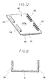
- Fig. 12 shows a fixing plate 60 comprising a plate 61 which has approximately the same form as the bottom surface of the case 31 and has L-shaped engaging projections 62 at its four corners. The projections 62 engage with the grooves 56, 57 and slide therein.
- a suitable joining means for example double-surface-adhering tape 63, is adhered to the back surface of the plate 61.
- the disposing box B can be attached to a wall W by engaging the projection 62 of the fixing plate 60 with the grooves 57 as shown in Fig. 14. Further, the disposing box 8 can be attached to the floor or desk by engaging the projections 62 of the fixing plate 60 with the grooves 56 as shown in Fig. 15.
- the syringe 20 is inserted into the guide hole 32 to fit the hub 22 in the opening defined by the holding portion 45 of the movable member 38 and the holding portion 44 of the fixed member 37 (see Fig. 10).
- the syringe 20 is rotated anticlockwise to release the screw connection between injection needle 21 and syringe 20.
- the pulling out of the syringe 20 from the guide hole 32 causes the injection needle 21 to be held by the movable member 38 and fixed member 37 and to be remained in the case 31.
- the injection needle 21 is firmly held by the holding portion 45 of the movable member 33 and holding portion 44 of the fixed member 37 mainly due to elasticity of the hub 22 itself.
- the injection needle 21 removed from the syringe 20 and held by the holding portions 44, 45 can be dropped into and contained in the case 31 through depressing the movable member 38 by using the operation rod 34. In that case, the injection needle 21 can be securely dropped into the case 31 since a needle 23 on the side of the liquid drug drops through the slit 33.
- the cap 35 is detached from the operation rod 34 and pressed into the opening of the guide hole 32, so that the jumping out or protruding of contained injection needle from inside the case is prevented.
- the disposing box of the present invention can be preferably used in discarding screw-type injection needled, or Lure-lock-type injection needles.
- the disposing box When used in discarding double-edged injection needles or blood-gathering needles among the above mentioned injection needles, the disposing box remarkably exhibits its convenience due to the holding effect of the holding portion.
- a box for disposing of used injection needles comprising a case having an opening whereinto a tip portion of a syringe is inserted, a movable member, and a fixed member, both members being arranged in the case.
- a hub of an injection needle inserted through the opening of the case is firmly held by holding portions of movable member and fixed member due to elasticity of the hub itself.
- the rotation of the syringe causes the injection needle to be removed from the syringe, and the removed injection needle, which is not pulled out together with the syringe and remained in the holding portions due to holding effect of the holding portions, can be dropped into the case by the operation of a rod outside the case.
Landscapes
- Health & Medical Sciences (AREA)
- Engineering & Computer Science (AREA)
- Heart & Thoracic Surgery (AREA)
- Vascular Medicine (AREA)
- Anesthesiology (AREA)
- Biomedical Technology (AREA)
- Environmental & Geological Engineering (AREA)
- Hematology (AREA)
- Life Sciences & Earth Sciences (AREA)
- Animal Behavior & Ethology (AREA)
- General Health & Medical Sciences (AREA)
- Public Health (AREA)
- Veterinary Medicine (AREA)
- Infusion, Injection, And Reservoir Apparatuses (AREA)
- Accommodation For Nursing Or Treatment Tables (AREA)
Claims (5)
- Boîte pour l'élimination d'aiguilles d'injection usagées, caractérisée par :
un boîtier (1, 31) ayant une ouverture (2, 32) sur sa surface supérieure ou latérale, dans laquelle une partie d'extrémité d'une seringue (20) peut être insérée, et- un moyen de blocage d'aiguille d'injection (3, 4; 37, 38) qui est disposé dans le boîtier (1, 31), et qui bloque une aiguille d'injection (21) disposée sur la seringue (20) insérée par l'ouverture (2, 32) et fait tomber l'aiguille d'injection (21) dans le boîtier (1, 31) après que l'aiguille d'injection (21) ait été séparée de la seringue (20) comprenant :- un élément mobile (3, 38) ayant une partie de maintien (9, 45) pour maintenir un axe (22) de l'aiguille d'injection (21),- un élément fixe (4, 37) ayant une partie de maintien (5, 44) pour maintenir l'axe (22) de l'aiguille d'injection (21) en coopération avec l'élément mobile (3, 38) et étant fixé au boîtier (1, 31),- un moyen élastique (6, 43) disposé de façon que la direction de sa force élastique soit parallèle au sens de déplacement de l'élément mobile (3, 38), une extrémité du moyen élastique (6, 43) étant fixée à ou on contact avec l'élément mobile (3, 38),- des parties de maintien (9, 15, 5, 44) qui sont définies par l'élément mobile (3, 38) et l'élément fixe (4, 37) et qui sont adaptées à la forme de l'axe (22) et forment une ouverture (12, 72) dont la taille est légèrement inférieure à celle d'une section transversale de l'axe (22),- une encoche (16, 33) se prolongeant jusqu'à la partie de maintien (5, 44) de l'élément fixe (4, 37) et formée sur l'élément fixe (4, 37) pour permettre le mouvement de l'axe (22) qui est séparé de la seringue (20) et est maintenu par la partie de maintien (5, 44) de l'élément fixe (4, 37) associé à la partie de maintien (9, 45) de l'élément mobile (3, 38, et- une tige (7, 34) pour déplacer l'élément mobile (3, 38) à l'encontre de la force élastique du moyen élastique (6, 43), une partie de celle-ci dépassant vers l'extérieur du boîtier (1, 31). - Boîte pour l'élimination d'aiguilles d'injection usagées selon la revendication 1, caractérisée en ce que :- l'ouverture (32) est sous la forme d'un trou de guidage tubulaire (32) disposé latéralement sur la boîte et permettant l'insertion de la partie d'extrémité de la seringue (20),
l'encoche (33) est réalisée sous la forme d'une fente (33) disposée sur une surface inférieure du trou de guidage (32) et permettant la chute de l'aiguille d'injection (21) et- le moyen de fixation d'aiguille d'injection (3, 4; 37, 38) pour maintenir l'axe (22) de l'aiguille d'injection (21) à la partie d'extrémité de la seringue (20) est situé sur la partie intérieure du trou de guidage (32). - Boîte pour' l'élimination d'aiguilles d'injection usagées selon la revendication 1 et 2, caractérisée en ce que le moyen élastique (6, 43) est un ressort.
- Boîte pour l'élimination d'aiguilles d'injection usagées selon la revendication 1 à 3, caractérisée par un capuchon (10, 35) capable de s'engager alternativement sur une extrémité de la tige (7, 34) et l'ouverture (2, 32).
- Boîte pour l'élimination d'aiguilles d'injection usagées selon la revendication 1 à 4, caractérisée en ce qu'au moins une gorge (56, 57) pour le montage et le démontage d'une plaque de fixation (60) est formée sur la paroi latérale du boîtier (1, 31).
Applications Claiming Priority (4)
| Application Number | Priority Date | Filing Date | Title |
|---|---|---|---|
| JP249345/87 | 1987-10-01 | ||
| JP62249345A JPH0191867A (ja) | 1987-10-01 | 1987-10-01 | 使用済注射針の廃棄箱 |
| JP72402/88 | 1988-03-25 | ||
| JP7240288A JPH062147B2 (ja) | 1988-03-25 | 1988-03-25 | 使用済注射針の廃棄箱 |
Publications (3)
| Publication Number | Publication Date |
|---|---|
| EP0309965A2 EP0309965A2 (fr) | 1989-04-05 |
| EP0309965A3 EP0309965A3 (en) | 1989-11-02 |
| EP0309965B1 true EP0309965B1 (fr) | 1992-05-27 |
Family
ID=26413535
Family Applications (1)
| Application Number | Title | Priority Date | Filing Date |
|---|---|---|---|
| EP88115826A Expired - Lifetime EP0309965B1 (fr) | 1987-10-01 | 1988-09-26 | Récipient de réception d'aiguilles d'injection usagées |
Country Status (4)
| Country | Link |
|---|---|
| US (1) | US4922597A (fr) |
| EP (1) | EP0309965B1 (fr) |
| CA (1) | CA1291914C (fr) |
| DE (1) | DE3871477D1 (fr) |
Families Citing this family (19)
| Publication number | Priority date | Publication date | Assignee | Title |
|---|---|---|---|---|
| FR2622875B1 (fr) * | 1987-11-06 | 1991-11-29 | Specialites Pharmaceutiq Centr | Boite recuperatrice de dechets dangereux |
| JPH0451789Y2 (fr) * | 1988-02-04 | 1992-12-07 | ||
| US4951685A (en) * | 1988-05-12 | 1990-08-28 | Blair Paul A | Blood drawing system |
| US5188598A (en) * | 1988-09-23 | 1993-02-23 | Post Medical, Inc. | Apparatus and method for safely disposing contaminated needles |
| EP0441628B1 (fr) * | 1990-02-09 | 1996-07-31 | Damal Limited | Assemblages d'aiguille hypodermique/seringue et dispositif pour démonter les aiguilles de ceux-ci |
| US5067949A (en) * | 1990-04-23 | 1991-11-26 | Freundlich Lawrence F | Instrument for unsheathing, resheathing and disposing of a medical syringe needle |
| US5069667A (en) * | 1990-07-24 | 1991-12-03 | Freundlich Lawrence F | Device for effecting safe removal of a used needle |
| USD328810S (en) | 1990-09-28 | 1992-08-18 | Chesapeake Packaging Company | Syringe collection container or the like |
| US5065939A (en) * | 1990-09-28 | 1991-11-19 | Chesapeake Packaging Company | Sharps container and blank |
| GB2254787A (en) * | 1991-04-15 | 1992-10-21 | Errol Arthur Landsberg | A device for use in detaching hypodermic needles |
| US5273161A (en) * | 1991-05-31 | 1993-12-28 | Medical Safety Products, Inc. | Needle disposal system comprised of blood collection holder and companion biohazard receptacle |
| US5193678A (en) * | 1992-03-12 | 1993-03-16 | Packaging Service Corporation Of Kentucky | Apparatus for counting and disposing of expendable medical items, including sharps and the like |
| US5275280A (en) * | 1992-05-08 | 1994-01-04 | Everhart Shawn L | Device and method of removal and storage of syringe needle |
| US5469964A (en) * | 1994-03-29 | 1995-11-28 | Bailey; Eddy R. | Multiple syringe unsheathing and resheathing device |
| IN189561B (fr) | 1996-06-21 | 2003-03-29 | Bio Plexus Inc | |
| US8522974B2 (en) | 2004-11-15 | 2013-09-03 | Becton, Dickinson And Company | Sharps container |
| CN103736177A (zh) * | 2013-12-27 | 2014-04-23 | 朱柳柳 | 一种拔针器 |
| CN107596507B (zh) * | 2017-09-19 | 2020-10-27 | 南京引光医药科技有限公司 | 一种用于医疗临床金属针头回收用夹板装置 |
| CN107928936B (zh) * | 2017-11-28 | 2020-12-04 | 浙江华福医用器材有限公司 | 一种医护人员用医疗车 |
Family Cites Families (5)
| Publication number | Priority date | Publication date | Assignee | Title |
|---|---|---|---|---|
| US4552280A (en) * | 1981-11-26 | 1985-11-12 | Owen William R | Containers for waste products |
| US4466538A (en) * | 1983-04-15 | 1984-08-21 | Biosafety Systems, Inc. | Hypodermic needle disposal system |
| GB2192382A (en) * | 1986-07-09 | 1988-01-13 | Anthony Lees | Container for disposal of used hypodermic needles |
| US4738362A (en) * | 1987-09-21 | 1988-04-19 | Beral Enterprises | Device for removal and disposal of syringe needles |
| US4807344A (en) * | 1987-10-13 | 1989-02-28 | Lance P. Kelson | Medical sampling needle removal and disposal device |
-
1988
- 1988-09-26 DE DE8888115826T patent/DE3871477D1/de not_active Expired - Fee Related
- 1988-09-26 EP EP88115826A patent/EP0309965B1/fr not_active Expired - Lifetime
- 1988-09-29 CA CA000578865A patent/CA1291914C/fr not_active Expired - Fee Related
- 1988-09-30 US US07/251,460 patent/US4922597A/en not_active Expired - Fee Related
Also Published As
| Publication number | Publication date |
|---|---|
| DE3871477D1 (de) | 1992-07-02 |
| CA1291914C (fr) | 1991-11-12 |
| EP0309965A2 (fr) | 1989-04-05 |
| EP0309965A3 (en) | 1989-11-02 |
| US4922597A (en) | 1990-05-08 |
Similar Documents
| Publication | Publication Date | Title |
|---|---|---|
| EP0309965B1 (fr) | Récipient de réception d'aiguilles d'injection usagées | |
| AU2004229083B2 (en) | Passive safety device for needle of blood collection set | |
| US4801013A (en) | Containment device for safely removing, storing and ultimately disposing of needles from hypodermic needle/syringe assemblies | |
| US6537259B1 (en) | Passive safety device | |
| JP2651487B2 (ja) | 医療蝶型針用鞘部 | |
| JPH0451789Y2 (fr) | ||
| JP2723105B2 (ja) | 採血針ホルダー | |
| EP0343803A2 (fr) | Dispositif de sécurité pour l'introduction d'un cathéter | |
| JPH0336362Y2 (fr) | ||
| EP0502115A4 (en) | Combination sterile pad support and lancet containing lancet disposal element | |
| JP2004194953A (ja) | 液体移注具 | |
| JP2004538103A (ja) | 引込み式安全針装置 | |
| US20210170092A1 (en) | Pen needle assembly apparatus | |
| US4956907A (en) | Method for safely removing, storing and ultimately disposing of needles from hypodermic needle/syringe assemblies | |
| US20210038827A1 (en) | A casing | |
| JPH0337408B2 (fr) | ||
| JP7266605B2 (ja) | ペンニードル組立体器具 | |
| US5275280A (en) | Device and method of removal and storage of syringe needle | |
| CN209900309U (zh) | 笔式针组件装置 | |
| CN209378203U (zh) | 笔针组装设备 | |
| JPH062147B2 (ja) | 使用済注射針の廃棄箱 | |
| JP7246397B2 (ja) | ペンニードルアセンブリ装置 | |
| CN110384841B (zh) | 笔式针组件装置 | |
| CN109966596B (zh) | 笔针组装设备 | |
| CN110898291B (zh) | 笔针设备 |
Legal Events
| Date | Code | Title | Description |
|---|---|---|---|
| PUAI | Public reference made under article 153(3) epc to a published international application that has entered the european phase |
Free format text: ORIGINAL CODE: 0009012 |
|
| AK | Designated contracting states |
Kind code of ref document: A2 Designated state(s): DE FR GB IT SE |
|
| PUAL | Search report despatched |
Free format text: ORIGINAL CODE: 0009013 |
|
| AK | Designated contracting states |
Kind code of ref document: A3 Designated state(s): DE FR GB IT SE |
|
| 17P | Request for examination filed |
Effective date: 19891227 |
|
| 17Q | First examination report despatched |
Effective date: 19910225 |
|
| GRAA | (expected) grant |
Free format text: ORIGINAL CODE: 0009210 |
|
| AK | Designated contracting states |
Kind code of ref document: B1 Designated state(s): DE FR GB IT SE |
|
| REF | Corresponds to: |
Ref document number: 3871477 Country of ref document: DE Date of ref document: 19920702 |
|
| ET | Fr: translation filed | ||
| ITF | It: translation for a ep patent filed | ||
| PLBE | No opposition filed within time limit |
Free format text: ORIGINAL CODE: 0009261 |
|
| STAA | Information on the status of an ep patent application or granted ep patent |
Free format text: STATUS: NO OPPOSITION FILED WITHIN TIME LIMIT |
|
| 26N | No opposition filed | ||
| PGFP | Annual fee paid to national office [announced via postgrant information from national office to epo] |
Ref country code: FR Payment date: 19930909 Year of fee payment: 6 |
|
| PGFP | Annual fee paid to national office [announced via postgrant information from national office to epo] |
Ref country code: GB Payment date: 19930916 Year of fee payment: 6 |
|
| PGFP | Annual fee paid to national office [announced via postgrant information from national office to epo] |
Ref country code: SE Payment date: 19930917 Year of fee payment: 6 |
|
| PGFP | Annual fee paid to national office [announced via postgrant information from national office to epo] |
Ref country code: DE Payment date: 19930922 Year of fee payment: 6 |
|
| PG25 | Lapsed in a contracting state [announced via postgrant information from national office to epo] |
Ref country code: GB Effective date: 19940926 |
|
| PG25 | Lapsed in a contracting state [announced via postgrant information from national office to epo] |
Ref country code: SE Effective date: 19940927 |
|
| EAL | Se: european patent in force in sweden |
Ref document number: 88115826.5 |
|
| GBPC | Gb: european patent ceased through non-payment of renewal fee |
Effective date: 19940926 |
|
| PG25 | Lapsed in a contracting state [announced via postgrant information from national office to epo] |
Ref country code: FR Effective date: 19950531 |
|
| PG25 | Lapsed in a contracting state [announced via postgrant information from national office to epo] |
Ref country code: DE Effective date: 19950601 |
|
| EUG | Se: european patent has lapsed |
Ref document number: 88115826.5 |
|
| REG | Reference to a national code |
Ref country code: FR Ref legal event code: ST |
|
| PG25 | Lapsed in a contracting state [announced via postgrant information from national office to epo] |
Ref country code: IT Free format text: LAPSE BECAUSE OF NON-PAYMENT OF DUE FEES;WARNING: LAPSES OF ITALIAN PATENTS WITH EFFECTIVE DATE BEFORE 2007 MAY HAVE OCCURRED AT ANY TIME BEFORE 2007. THE CORRECT EFFECTIVE DATE MAY BE DIFFERENT FROM THE ONE RECORDED. Effective date: 20050926 |