EP0310116A2 - Gerät zur Stromversorgung eines Motorantriebes einschliesslich Regelschleife für den Schaltregler - Google Patents
Gerät zur Stromversorgung eines Motorantriebes einschliesslich Regelschleife für den Schaltregler Download PDFInfo
- Publication number
- EP0310116A2 EP0310116A2 EP88116208A EP88116208A EP0310116A2 EP 0310116 A2 EP0310116 A2 EP 0310116A2 EP 88116208 A EP88116208 A EP 88116208A EP 88116208 A EP88116208 A EP 88116208A EP 0310116 A2 EP0310116 A2 EP 0310116A2
- Authority
- EP
- European Patent Office
- Prior art keywords
- voltage
- circuit
- motor
- signal
- switching regulator
- Prior art date
- Legal status (The legal status is an assumption and is not a legal conclusion. Google has not performed a legal analysis and makes no representation as to the accuracy of the status listed.)
- Granted
Links
Images

Classifications
-
- H—ELECTRICITY
- H02—GENERATION; CONVERSION OR DISTRIBUTION OF ELECTRIC POWER
- H02P—CONTROL OR REGULATION OF ELECTRIC MOTORS, ELECTRIC GENERATORS OR DYNAMO-ELECTRIC CONVERTERS; CONTROLLING TRANSFORMERS, REACTORS OR CHOKE COILS
- H02P7/00—Arrangements for regulating or controlling the speed or torque of electric DC motors
- H02P7/06—Arrangements for regulating or controlling the speed or torque of electric DC motors for regulating or controlling an individual DC dynamo-electric motor by varying field or armature current
- H02P7/18—Arrangements for regulating or controlling the speed or torque of electric DC motors for regulating or controlling an individual DC dynamo-electric motor by varying field or armature current by master control with auxiliary power
- H02P7/24—Arrangements for regulating or controlling the speed or torque of electric DC motors for regulating or controlling an individual DC dynamo-electric motor by varying field or armature current by master control with auxiliary power using discharge tubes or semiconductor devices
- H02P7/28—Arrangements for regulating or controlling the speed or torque of electric DC motors for regulating or controlling an individual DC dynamo-electric motor by varying field or armature current by master control with auxiliary power using discharge tubes or semiconductor devices using semiconductor devices
- H02P7/285—Arrangements for regulating or controlling the speed or torque of electric DC motors for regulating or controlling an individual DC dynamo-electric motor by varying field or armature current by master control with auxiliary power using discharge tubes or semiconductor devices using semiconductor devices controlling armature supply only
- H02P7/29—Arrangements for regulating or controlling the speed or torque of electric DC motors for regulating or controlling an individual DC dynamo-electric motor by varying field or armature current by master control with auxiliary power using discharge tubes or semiconductor devices using semiconductor devices controlling armature supply only using pulse modulation
- H02P7/2913—Arrangements for regulating or controlling the speed or torque of electric DC motors for regulating or controlling an individual DC dynamo-electric motor by varying field or armature current by master control with auxiliary power using discharge tubes or semiconductor devices using semiconductor devices controlling armature supply only using pulse modulation whereby the speed is regulated by measuring the motor speed and comparing it with a given physical value
-
- Y—GENERAL TAGGING OF NEW TECHNOLOGICAL DEVELOPMENTS; GENERAL TAGGING OF CROSS-SECTIONAL TECHNOLOGIES SPANNING OVER SEVERAL SECTIONS OF THE IPC; TECHNICAL SUBJECTS COVERED BY FORMER USPC CROSS-REFERENCE ART COLLECTIONS [XRACs] AND DIGESTS
- Y10—TECHNICAL SUBJECTS COVERED BY FORMER USPC
- Y10S—TECHNICAL SUBJECTS COVERED BY FORMER USPC CROSS-REFERENCE ART COLLECTIONS [XRACs] AND DIGESTS
- Y10S388/00—Electricity: motor control systems
- Y10S388/907—Specific control circuit element or device
- Y10S388/915—Sawtooth or ramp waveform generator
Definitions
- the present invention generally relates to a power supply apparatus for driving a DC motor. More specifically, the invention is directed to a power supply apparatus for driving, for instance, a motor of a cassette player built in an automobile, in which a power loss occurred in a series regulator is minimized and malfunction caused by such a heat loss of circuit components is prevented.
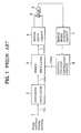
- Fig. 1 is a block diagram of the conventional power supply apparatus for driving the DC motor.
- a DC (direct current) voltage V IN from a battery (not shown in detail) for a car power source is applied via a DC voltage input terminal 1 to a switching regulator 2.
- An output voltage V out1 of this switching regulator 2 is applied to the subsequent series regulator 3.
- An output voltage V out2 of the series regulator 3 is further applied to a motor drive circuit 4.
- This motor drive circuit 4 is used for, for instance, driving a motor 5 of a cassette player built in a vehicle.
- a sensor output from the sensor element 6 is supplied to a motor speed judging circuit 7.
- a comparison is performed between the sensor output from the sensor element 6 and a predetermined reference signal. Depending upon the comparison result, a predetermined output signal is supplied from this motor speed judging circuit 7 to a control voltage generating circuit 8.
- a control voltage V REG derived from the control voltage generating circuit 8 is applied to the above-described series regulator 3, whereby the output voltage V OUT2 from the series regulator 3 is properly controlled based upon this control voltage V REG .
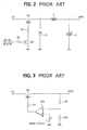
- Fig. 2 is a schematic circuit diagram of a typical switching regulator.
- an emitter of a switching transistor Q1 is connected to an input section (IN) of a power supply (not shown), and a diode D is connected between a collector of the switching transistor Q1 and a ground.
- a base of this switching transistor Q1 is connected via a resistor R1 to a collector of a controlling transistor Q2.
- a controlling signal is supplied via a resistor R2 to a base of this controlling transistor Q2, whereas an emitter thereof is grounded.
- a series circuit consisting of a filtering inductor "L” and a capacitor “C” is parallel-connected. Another junction between the inductor "L” and capacitor “C” is connected to an output section (OUT) of the above-described power supply.
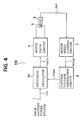
- Fig. 3 is a schematic circuit diagram of a typical series regulator.
- a collector of a transistor Q3 is connected to the input section (IN) of the power supply whereas an emitter thereof is connected to the output section (OUT) of the power supply.
- a series circuit consisting of resistors R4 and R5 is connected between the output section (OUT) of the power supply and a ground line.
- a junction between these resistors R4 and R5 is connected to one terminal of a differential amplifier (DA) whereas a predetermined reference voltage "E REF " is applied to the other input terminal thereof.
- This voltage "E REF " corresponds to the above control voltage V REF .
- An output terminal of this differential amplifier DA is connected via a resistor R3 to a base of the transistor Q3.
- this series regulator 3 shown in Fig. 3 employs the transistor Q3 connected between the power source input unit (IN) and power source output unit (OUT), and this transistor Q3 will cause a voltage drop in the emitter-to-collector path. As a consequence, an unnecessary power loss may be induced therein, and thus this transistor Q3 is heated by herself, resulting in the malfunction of the circuitry.
- the above-described conventional motor driving power supply apparatus may be applicable to the cassette player built in the vehicle.
- the voltage to be applied to the motor 5 is low during the playback (reproducing) operation, i.e., the low speed mode, whereas this motor voltage becomes high during the fast forward (FF) operation, i.e., the high speed mode.
- the high voltage is continuously applied which is required during the above-described high speed mode.
- the required voltage drop in this collector-to-emitter path of the transistor Q3 must be set higher. As a result, the unwanted power loss will be increased, and thus, the occurrence of the malfunction of the circuit elements due to the higher heat problem will be emphasized.
- the present invention has been made in an attempt to solve the above-described conventional problems, and has an object to provide a novel power supply apparatus for driving a DC motor, wherein the voltage control to the motor is carried out at the switching regulator stage.
- Another object of the present invention is to provide a power supply apparatus for driving a DC motor, wherein unnecessary power consumption is minimized to avoid heat problems of circuit components.
- a power supply apparatus (100) for driving a motor comprising: a switching regulator circuit (20) for regulating a DC (direct current) input voltage (V IN ) to produce a desired DC output voltage (V OUT3 ); a motor driving circuit (4) for driving a motor (5) by receiving the DC output voltage (V OUT3 ) of the switching regulator circuit (20); a sensor element (6) for sensing a speed of the motor (5) to output a sensor signal (S MT ); a motor speed judging circuit (7) for comparing said sensor signal (S MT ) from the sensor element (6) with a reference signal to produce a judgement signal (S COMP ); and a control voltage generating circuit (8) for producing a control voltage (V REG ) based upon the judgement signal "S COMP " of the motor speed judgement circuit (7), whereby the DC output voltage (V OUT3 ) of the switching regulator circuit (20) is controlled in response to the control voltage (V REG ).
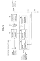
- FIG. 4 a circuit block diagram of an overall circuit arrangement of a motor driving power supply apparatus 100 according to a preferred embodiment of the invention will now be described.
- a DC voltage V IN derived from a car battery (not shown) as a power source of an automobile is applied to a switching regulator 20.
- This switching regulator 20 has the function of the conventional switching regulator 2 shown in Fig. 1 in addition to the featured functions of the invention (will be described later).
- a controlled output voltage V OUT3 from the switching regulator 20 is applied to the motor drive circuit 4.
- This motor drive circuit 4 is similarly used for driving the DC motor 5 of the cassette player built in the automobile (not shown in detail).
- the motor speed sensor element 6 is positioned adjacent to the motor 5.
- a sensor signal "S MT " from the sensor element 6 is supplied to the subsequent motor speed judging circuit 7. In the motor speed judging circuit 7, this sensor signal S MT is compared with a preset reference signal.
- a predetermined output signal "S COMP " derived from this motor speed judging circuit 7 is supplied to the control voltage generating circuit 8.
- the control voltage V REG of the control voltage generating circuit 8 is applied to the above-described switching regulator 20, so that the output voltage V OUT3 derived from this switching regulator 20 is properly adjusted, or varied so as to establish the optimum motor driving condition.
- Fig. 5 there is shown an internal circuit of the switching regulator 20.
- the input voltage V IN from the battery power source is applied to an 0N/OFF switching circuit 21.
- An output of the switching circuit 21 is converted by a transformer 22 into a proper output voltage.
- the converted output voltage is then filtered in a filter circuit 23.
- the filter output voltage is applied as V OUT3 to the motor drive circuit 4 of Fig. 4.
- the output voltage V OUT3 of the switching regulator 20 is subdivided by a series circuit of resistors R10 and R12 to produce a subdivided voltage V OUT3′ .
- this subdivided voltage V OUT3′ is compared with the control voltage V REG supplied from the control voltage generating circuit 8.
- a comparison resultant signal V CA is output from this first voltage comparator 24 and transferred to a second voltage comparator 25. If required, this comparison resultant signal may be amplified before supplied to the second comparator 25.
- another input signal i.e., a triangle waveform signal V CB is supplied from a triangle waveform generator 26.
- the 0N/OFF switching circuit 21 is turned ON in response to an output from the second voltage comparator 25. Conversely, this switching circuit 21 is turned OFF under the condition of V CA > V CB .
- control voltage V REG is a fixed voltage, or has a very low frequency compared with the frequency of the triangle waveform signal V CB , an arbitrary fixed output voltage V OUT3 can be obtained in the switching regulator 20 shown in Fig. 4.
- the motor driving power supply apparatus 100 has the following feature. That is, the specific switching regulator 20 is incorporated in the voltage control loop so as to control the output voltage V OUT3 without an occurrence of the unwanted heat dissipation.
- an amplifier may be interposed between the first and second voltage comparators 24 and 25.
- the circuit arrangements represented by a dot line of Fig. 5 may be fabricated by an integrated circuit.
Landscapes
- Engineering & Computer Science (AREA)
- Power Engineering (AREA)
- Control Of Direct Current Motors (AREA)
- Dc-Dc Converters (AREA)
- Control Of Electric Motors In General (AREA)
Applications Claiming Priority (2)
| Application Number | Priority Date | Filing Date | Title |
|---|---|---|---|
| JP62247917A JPH0191689A (ja) | 1987-10-02 | 1987-10-02 | モータ駆動用電源装置 |
| JP247917/87 | 1987-10-02 |
Publications (3)
| Publication Number | Publication Date |
|---|---|
| EP0310116A2 true EP0310116A2 (de) | 1989-04-05 |
| EP0310116A3 EP0310116A3 (en) | 1989-10-11 |
| EP0310116B1 EP0310116B1 (de) | 1993-09-15 |
Family
ID=17170476
Family Applications (1)
| Application Number | Title | Priority Date | Filing Date |
|---|---|---|---|
| EP88116208A Expired - Lifetime EP0310116B1 (de) | 1987-10-02 | 1988-09-30 | Gerät zur Stromversorgung eines Motorantriebes einschliesslich Regelschleife für den Schaltregler |
Country Status (7)
| Country | Link |
|---|---|
| US (1) | US5040235A (de) |
| EP (1) | EP0310116B1 (de) |
| JP (1) | JPH0191689A (de) |
| KR (1) | KR920004733B1 (de) |
| AU (1) | AU599514B2 (de) |
| CA (1) | CA1296763C (de) |
| DE (1) | DE3884121T2 (de) |
Cited By (2)
| Publication number | Priority date | Publication date | Assignee | Title |
|---|---|---|---|---|
| AU599514B2 (en) * | 1987-10-02 | 1990-07-19 | Mitsubishi Denki Kabushiki Kaisha | Motor driving power supply apparatus including switching regulator control loop |
| GB2280519A (en) * | 1990-08-28 | 1995-02-01 | Toshiba Kk | Clothes washing machine with motor speed control |
Families Citing this family (4)
| Publication number | Priority date | Publication date | Assignee | Title |
|---|---|---|---|---|
| US5347895A (en) * | 1991-09-20 | 1994-09-20 | Fmc Corporation | Brake lathe with electronic feed control |
| US6747424B1 (en) | 2000-10-02 | 2004-06-08 | International Business Machines Corporation | Integrated fan speed control and fault detection circuitry |
| US8075457B2 (en) | 2004-02-24 | 2011-12-13 | Total Gym Global Corp. | Inclinable exercise device with abdominal crunch board and method |
| JP2014007805A (ja) * | 2012-06-22 | 2014-01-16 | Aisin Seiki Co Ltd | 直流モータの速度制御装置 |
Family Cites Families (14)
| Publication number | Priority date | Publication date | Assignee | Title |
|---|---|---|---|---|
| US3710216A (en) * | 1971-04-06 | 1973-01-09 | Eaton Corp | Scr motor speed control with plug sensing circuit |
| US3952236A (en) * | 1974-07-19 | 1976-04-20 | General Electric Company | Vehicle speed regulation system |
| US4153853A (en) * | 1976-07-07 | 1979-05-08 | Villeneuve Dail A De | DC motor speed controller |
| GB1594572A (en) * | 1976-11-02 | 1981-07-30 | Lucas Industries Ltd | Control circuits for electric traction motors for vehicles |
| US4121141A (en) * | 1977-05-13 | 1978-10-17 | Fairchild Camera And Instrument Corporation | D.C. motor speed control circuitry |
| JPS5513673A (en) * | 1978-07-15 | 1980-01-30 | Sony Corp | Servo-circuit of direct current motor |
| JPS5629469A (en) * | 1979-08-16 | 1981-03-24 | Sony Corp | Switching control circuit |
| US4427931A (en) * | 1980-10-17 | 1984-01-24 | Sanyo Electric Co., Ltd. | Speed control apparatus for direct current motor |
| JPS597964A (ja) * | 1982-07-06 | 1984-01-17 | Canon Inc | 記録媒体駆動装置 |
| DE3377849D1 (en) * | 1982-09-17 | 1988-09-29 | Kudelski Sa | Control system for an electric motor |
| JPH0616329B2 (ja) * | 1984-06-14 | 1994-03-02 | ソニー株式会社 | Vtrのpwm方式モ−タドライブ回路 |
| US4635927A (en) * | 1985-03-04 | 1987-01-13 | Del Mar Avionics | Low power treadmill |
| JPS6216085A (ja) * | 1985-07-12 | 1987-01-24 | Hitachi Seiko Ltd | 直流モ−タの駆動制御装置 |
| JPH0191689A (ja) * | 1987-10-02 | 1989-04-11 | Mitsubishi Electric Corp | モータ駆動用電源装置 |
-
1987
- 1987-10-02 JP JP62247917A patent/JPH0191689A/ja active Pending
-
1988
- 1988-09-05 KR KR1019880011449A patent/KR920004733B1/ko not_active Expired
- 1988-09-30 US US07/251,810 patent/US5040235A/en not_active Expired - Fee Related
- 1988-09-30 AU AU23300/88A patent/AU599514B2/en not_active Ceased
- 1988-09-30 DE DE88116208T patent/DE3884121T2/de not_active Expired - Fee Related
- 1988-09-30 CA CA000578996A patent/CA1296763C/en not_active Expired - Lifetime
- 1988-09-30 EP EP88116208A patent/EP0310116B1/de not_active Expired - Lifetime
Cited By (3)
| Publication number | Priority date | Publication date | Assignee | Title |
|---|---|---|---|---|
| AU599514B2 (en) * | 1987-10-02 | 1990-07-19 | Mitsubishi Denki Kabushiki Kaisha | Motor driving power supply apparatus including switching regulator control loop |
| GB2280519A (en) * | 1990-08-28 | 1995-02-01 | Toshiba Kk | Clothes washing machine with motor speed control |
| GB2280519B (en) * | 1990-08-28 | 1995-05-10 | Toshiba Kk | Clothes washing machine |
Also Published As
| Publication number | Publication date |
|---|---|
| EP0310116A3 (en) | 1989-10-11 |
| KR920004733B1 (ko) | 1992-06-15 |
| JPH0191689A (ja) | 1989-04-11 |
| DE3884121D1 (de) | 1993-10-21 |
| AU2330088A (en) | 1989-04-06 |
| CA1296763C (en) | 1992-03-03 |
| US5040235A (en) | 1991-08-13 |
| EP0310116B1 (de) | 1993-09-15 |
| AU599514B2 (en) | 1990-07-19 |
| KR890007486A (ko) | 1989-06-20 |
| DE3884121T2 (de) | 1994-01-13 |
Similar Documents
| Publication | Publication Date | Title |
|---|---|---|
| US5940235A (en) | Reproducing circuit for a magnetic head incorporating the voltage-to-current and an exponent current amplifier | |
| CA2019936C (en) | Semiconductor laser driving circuit | |
| EP0310116B1 (de) | Gerät zur Stromversorgung eines Motorantriebes einschliesslich Regelschleife für den Schaltregler | |
| US4994719A (en) | Voltage regulator with active turnoff | |
| US5309077A (en) | Apparatus and method for loading a cassette tape in a video equipment | |
| US5483390A (en) | Device for switching a video tape recorder head to write/read mode | |
| US5381277A (en) | Method and apparatus for decreasing a transition time of a read head from a write mode to a read mode | |
| US4317189A (en) | Voice frequency signal actuated tape recorder | |
| JP3681484B2 (ja) | トルクの低下を補償するための電子コミュテータ直流モータ用モータ制御器 | |
| US4520276A (en) | Zero-delay ramp generator | |
| JP2974319B2 (ja) | 電子機器 | |
| JPS6412181B2 (de) | ||
| US5708647A (en) | Laser power supply circuit as well as option recording and/or reading device comprising such a laser power supply circuit | |
| KR960008411Y1 (ko) | 레이저 디스크 플레이어의 스핀들 모터 제어회로 | |
| KR900002605B1 (ko) | 브이.티.알의 음성신호 처리용 기록, 재생, 뮤트모우드로직 조절회로 | |
| JPH039380Y2 (de) | ||
| US4639660A (en) | Switching circuit for a power supply in a signal processing apparatus | |
| JP2566303B2 (ja) | 磁気記録再生装置 | |
| KR900000491Y1 (ko) | 래코딩시 테이프 잔량에 의한 자동모드 절환회로 | |
| JPH0446003B2 (de) | ||
| JPH062372Y2 (ja) | Agc回路 | |
| SU1465937A1 (ru) | Мультивибратор | |
| JPS5914383A (ja) | 直流モ−タのスイツチングガバナ装置 | |
| US6147554A (en) | Control signal amplification circuit | |
| KR880002752Y1 (ko) | 음방향 피크검출 자동 입력 조절기를 내장한 저전압 증폭기 |
Legal Events
| Date | Code | Title | Description |
|---|---|---|---|
| PUAI | Public reference made under article 153(3) epc to a published international application that has entered the european phase |
Free format text: ORIGINAL CODE: 0009012 |
|
| AK | Designated contracting states |
Kind code of ref document: A2 Designated state(s): DE NL SE |
|
| PUAL | Search report despatched |
Free format text: ORIGINAL CODE: 0009013 |
|
| AK | Designated contracting states |
Kind code of ref document: A3 Designated state(s): DE NL SE |
|
| 17P | Request for examination filed |
Effective date: 19900322 |
|
| 17Q | First examination report despatched |
Effective date: 19920617 |
|
| GRAA | (expected) grant |
Free format text: ORIGINAL CODE: 0009210 |
|
| AK | Designated contracting states |
Kind code of ref document: B1 Designated state(s): DE NL SE |
|
| REF | Corresponds to: |
Ref document number: 3884121 Country of ref document: DE Date of ref document: 19931021 |
|
| PLBE | No opposition filed within time limit |
Free format text: ORIGINAL CODE: 0009261 |
|
| STAA | Information on the status of an ep patent application or granted ep patent |
Free format text: STATUS: NO OPPOSITION FILED WITHIN TIME LIMIT |
|
| 26N | No opposition filed | ||
| EAL | Se: european patent in force in sweden |
Ref document number: 88116208.5 |
|
| PGFP | Annual fee paid to national office [announced via postgrant information from national office to epo] |
Ref country code: SE Payment date: 19950918 Year of fee payment: 8 |
|
| PGFP | Annual fee paid to national office [announced via postgrant information from national office to epo] |
Ref country code: NL Payment date: 19950922 Year of fee payment: 8 |
|
| PGFP | Annual fee paid to national office [announced via postgrant information from national office to epo] |
Ref country code: DE Payment date: 19950928 Year of fee payment: 8 |
|
| PG25 | Lapsed in a contracting state [announced via postgrant information from national office to epo] |
Ref country code: SE Effective date: 19961001 |
|
| PG25 | Lapsed in a contracting state [announced via postgrant information from national office to epo] |
Ref country code: NL Effective date: 19970401 |
|
| NLV4 | Nl: lapsed or anulled due to non-payment of the annual fee |
Effective date: 19970401 |
|
| PG25 | Lapsed in a contracting state [announced via postgrant information from national office to epo] |
Ref country code: DE Effective date: 19970603 |
|
| EUG | Se: european patent has lapsed |
Ref document number: 88116208.5 |