EP0310146A2 - Exprimeur de pâte en tube - Google Patents
Exprimeur de pâte en tube Download PDFInfo
- Publication number
- EP0310146A2 EP0310146A2 EP88200319A EP88200319A EP0310146A2 EP 0310146 A2 EP0310146 A2 EP 0310146A2 EP 88200319 A EP88200319 A EP 88200319A EP 88200319 A EP88200319 A EP 88200319A EP 0310146 A2 EP0310146 A2 EP 0310146A2
- Authority
- EP
- European Patent Office
- Prior art keywords
- piston
- tube
- pinion
- expressor
- envelope
- Prior art date
- Legal status (The legal status is an assumption and is not a legal conclusion. Google has not performed a legal analysis and makes no representation as to the accuracy of the status listed.)
- Granted
Links
- 239000012530 fluid Substances 0.000 claims abstract description 5
- 230000001681 protective effect Effects 0.000 claims description 3
- 238000013519 translation Methods 0.000 claims description 2
- 239000006072 paste Substances 0.000 abstract description 4
- 239000000606 toothpaste Substances 0.000 abstract description 3
- 229940034610 toothpaste Drugs 0.000 abstract description 3
- 230000008901 benefit Effects 0.000 description 2
- 230000000694 effects Effects 0.000 description 2
- 238000000034 method Methods 0.000 description 2
- 238000012986 modification Methods 0.000 description 2
- 230000004048 modification Effects 0.000 description 2
- 239000004033 plastic Substances 0.000 description 2
- 235000010585 Ammi visnaga Nutrition 0.000 description 1
- 244000153158 Ammi visnaga Species 0.000 description 1
- 230000008859 change Effects 0.000 description 1
- 238000009795 derivation Methods 0.000 description 1
- 238000001035 drying Methods 0.000 description 1
- 230000003670 easy-to-clean Effects 0.000 description 1
- 238000002347 injection Methods 0.000 description 1
- 239000007924 injection Substances 0.000 description 1
- 238000009434 installation Methods 0.000 description 1
- 238000012423 maintenance Methods 0.000 description 1
- 239000000463 material Substances 0.000 description 1
- 230000007246 mechanism Effects 0.000 description 1
- 230000000750 progressive effect Effects 0.000 description 1
- 238000012360 testing method Methods 0.000 description 1
- 229920001169 thermoplastic Polymers 0.000 description 1
- 239000004416 thermosoftening plastic Substances 0.000 description 1
Images
Classifications
-
- B—PERFORMING OPERATIONS; TRANSPORTING
- B65—CONVEYING; PACKING; STORING; HANDLING THIN OR FILAMENTARY MATERIAL
- B65D—CONTAINERS FOR STORAGE OR TRANSPORT OF ARTICLES OR MATERIALS, e.g. BAGS, BARRELS, BOTTLES, BOXES, CANS, CARTONS, CRATES, DRUMS, JARS, TANKS, HOPPERS, FORWARDING CONTAINERS; ACCESSORIES, CLOSURES, OR FITTINGS THEREFOR; PACKAGING ELEMENTS; PACKAGES
- B65D35/00—Pliable tubular containers adapted to be permanently or temporarily deformed to expel contents, e.g. collapsible tubes for toothpaste or other plastic or semi-liquid material; Holders therefor
- B65D35/24—Pliable tubular containers adapted to be permanently or temporarily deformed to expel contents, e.g. collapsible tubes for toothpaste or other plastic or semi-liquid material; Holders therefor with auxiliary devices
- B65D35/28—Pliable tubular containers adapted to be permanently or temporarily deformed to expel contents, e.g. collapsible tubes for toothpaste or other plastic or semi-liquid material; Holders therefor with auxiliary devices for expelling contents
Definitions
- the invention relates to an expressor for tubes containing fluid paste.
- the invention consists of a tube dough expressor which proposes and which achieves the following aims and advantages: - It is activated with a simple and quick maneuver of the fingers. - He always responds with a prompt, precise and uniform expulsion. - He consents to exhaust the tube in a progressive and complete manner. - It is particularly suitable for being fixed to the wall and, for this, it eliminates the need to support and handle the tube, thus reducing the work of the hands. - It has a simple, reliable and resistant mechanism. - It is durable and requires no maintenance. - There are electrically assisted versions. - It is compatible with almost all tubes on the market. - It allows you to change the tube easily and quickly.
- the present tube dough expressor as recalled in the claims, is characterized in that it comprises a piston provided with a slot into which the rear part of a tube containing fluid dough is inserted. .
- This slot is silhouetted so that a relative coaxial sliding of the piston-tube system induces on the tube the pressure necessary to express the dough.
- the device also comprises a body suitable for serving as a support for said operating system, by constraining it properly and, at the same time, allowing it the necessary movement.
- This body is preferably constituted by a tubular envelope in which this piston can slide; said envelope is suitably closed at the ends, the lower closure constituting support for the tube, which is supported by its front part, except the spout which comes out through a hole present on this same bottom; the bottom in ques tion can optionally be accompanied by a protective cover.
- the above-mentioned envelope can easily be fixed to the wall by means, for example, of an appendage which emerges from the lateral surface, and provided with fixing means, for example holes for screws.
- the tube enters the envelope through one of the ends which can be opened, or else through a flap made in the lateral surface of the envelope.
- the piston will be pushed by any means capable of imparting a translation along its axis.
- a screw press is indicated which takes advantage, as a force support, of the closing of the envelope; said screw can be provided with a small handle for manual operation, or it can be actuated, by means of a special pinion, by an electric motor, supplied by network or by batteries.
- Another embodiment can be envisaged by inverting the arrangement of the rack-pinion system; that is to say by fixing the rack to the casing along a generator and mounting the pinion on the piston.
- the pinion must be within easy reach, which can be achieved by extending its axis through an opening in the envelope and completing it with a small handle; this opening can be a longitudinal groove, necessary and sufficient for the pinion to follow the piston stroke.
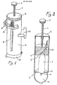
- the figures cited above refer to a tube dough expressor which comprises a cylindrical tubular casing 1 with the closed bottom 2 in which a piston 3 can slide pushed towards this bottom 2 by the screw a press 4 associated with the center of a first cover 5 screwed onto the same casing 1.
- This screw 4 on its end leaving this envelope 1, is provided with a small handle 6 for maneuvering.
- This piston 3 is provided in length with a slot 7 suitably silhouetted in a shape similar to a curved funnel, slot in which is inserted the rear portion 8 of a tube 9 containing toothpaste whose front portion 10 rests on the bottom 2 of said envelope 1.
- the end 11 of the tube 9 exits through a hole 12 in this bottom 2.
- this envelope 1 is provided with an appendage 13 suitable for fixing to the wall by means of screws, and with a crown 14 provided with holes 15 in which the toothbrushes 16 can be inserted.
- the pitch of screw 4 is calibrated so that a small rotation produces the requested expulsion.
- the loading is carried out as follows: on in troduit the tube 9 overturned in the casing 1 with its end 11 projecting through the hole 12, then we put the piston 3 taking care to insert the rear portion 8 of the tube 9 in the slot 7 and, at the end, screw the cover 5 which carries the screw 4.
- This invention can be carried out, in whole or in part, in plastic, any other suitable material that can however be used.
- each element can be replaced by another technically equivalent element; for example, the tubular casing can be replaced by another element having the same functions, such as for example a cage, even reduced to a few bars.
- the present dough tube expressor is, in all its forms, easily achievable in industry. It can actually be manufactured at reduced costs by means of the usual installations; in particular, the plastic parts can be obtained by stamping with a thermoplastic injection press.
Landscapes
- Engineering & Computer Science (AREA)
- Mechanical Engineering (AREA)
- Tubes (AREA)
- Mechanical Pencils And Projecting And Retracting Systems Therefor, And Multi-System Writing Instruments (AREA)
- Manufacturing Of Printed Wiring (AREA)
- Electric Connection Of Electric Components To Printed Circuits (AREA)
- Materials For Medical Uses (AREA)
- Noodles (AREA)
- Seal Device For Vehicle (AREA)
- Inorganic Insulating Materials (AREA)
- Food-Manufacturing Devices (AREA)
- Physical Or Chemical Processes And Apparatus (AREA)
Abstract
Description
- L'invention concerne un exprimeur pour tubes contenant de la pâte fluide.
- On sait que la méthode la plus commune pour presser un tube, par exemple de dentifrice, est celle qui consiste à l'écraser avec les doigts.
- Toutefois cette méthode-là n'est pas satisfaisante car au fur et à mesure que le tube s'amoindrit, de nouvelles difficultés surgissent, à cause de la tendance de la pâte à revenir aux zones déjà pressées.
- On sait aussi que l'opération de pressurage manuel comporte une certaine complication puisqu'il faut empoigner le tube, enlever le bouchon, presser le tube, puis revisser le bouchon et reposer le tube; le tout en maintenant, en même temps, la brosse à dents en position horizontale.
- L'invention consiste en un exprimeur de pâte en tube qui se propose et qui atteint les buts et avantages suivants:
- On l'actionne avec une simple et rapide manoeuvre des doigts.
- Il répond toujours par une expulsion prompte, précise et uniforme.
- Il consent d'épuiser le tube d'une manière progressive et complète.
- Il est particulièrement propre à être fixé au mur et, pour cela, il élimine la nécessité de soutenir et de manipuler le tube en réduisant ainsi le travail des mains.
- Il a un mécanisme simple, fiable et résistant.
- Il est durable et ne requiert aucun entretien.
- Il existe en versions assistées électriquement.
- Il est compatible avec presque tous les tubes en commerce.
- Il permet de rechanger le tube avec aisance et rapidité.
- On peut le munir d'un couvercle de protection contre la dessication de la pâte, couvercle qu'on peut ouvrir rapidement.
- Il est d'aspect agréable et il dissimule le tube à la vue.
- Il peut servir de support aux brosses à dents sans augmenter sensiblement l'encombrement (en tant que presse-dentif.).
- Il est de dimension réduite et constitue un ensemble compact.
- Il est facile à nettoyer car il a une surface uniforme et régulière.
- On peut l'employer de façon portative sans modifications significatives.
- Il n'est pas cher et pour cette raison il est largement accessible aux usagers. - Le présent exprimeur de pâte en tube, tel qu'on le rappelle dans les revendications, est caractérisé par le fait qu'il comprend un piston doté d'une fente dans laquelle on insère la partie postérieure d'un tube contenant de la pâte fluide. Cette fente est silhouettée de manière à ce qu'un relatif glissement coaxial du système piston-tube induise sur le tube la pression nécessaire pour exprimer la pâte.
- Le dispositif comprend aussi un corps propre à servir de support au dit système de fonctionnement, en le contraignant convenablement et, en même temps, en lui permettant le mouvement nécessaire. Ce corps est préférablement constitué par une enveloppe tubulaire dans lequel ce piston peut glisser; ladite enveloppe est convenablement fermée aux extrêmités, la fermeture inférieure constituant un soutien pour le tube, lequel est appuyé par sa partie antérieure, sauf le bec qui sort par un trou présent sur ce même fond; le fond en ques tion peut éventuellement être assorti d'un couvercle de protection. L'enveloppe sus-mentionnée peut facilment être fixée au mur au moyen, par exemple, d'un appendice qui se degage de la surface latérale, et pourvu de moyens de fixation, par exemple des trous pour vis.
- Le tube accède dans l'enveloppe par un des bouts susceptible d'être ouvert, ou bien par un volet pratiqué dans la surface latérale de l'enveloppe.
- Le piston sera poussé par n'importe quel moyen en mesure de lui imprimer une translation le long de son axe. Par exemple on indique une presse à vis qui profite, comme appui de force, de la fermeture de l'enveloppe; ladite vis peut être dotée d'une petite poignée pour la manoeuvre manuelle, ou bien, on peut l'actionner, par l'intermédiaire d'un pignon spécial, par un moteur électrique, alimenté en réseau ou par batteries.
- On peut obtenir une alternative équivalente à la réalisation précédente en remplaçant la presse à vis par une crémaillère gouvernée par un pignon qu'on peut tourner manuellement ou électriquement. Un tel mode de réalisation consent d'encastrer le piston à l'extrêmité inférieure de la crémaillère, de sorte qu'il est possible de commander le mouvement du piston dans les deux sens.
- Un autre mode de réalisation, analogue au précédent, est envisageable en invertissant la disposition du système crémaillère-pignon; c'est-à-dire en fixant la crémaillère à l'enveloppe le long d'une génératrice et en montant le pignon sur le piston. Naturellement le pignon doit être à portée de la main, ce qu'on peut obtenir en prolongeant son axe à travers une ouverture dans l'enveloppe et en le complétant par une petite poignée; cette ouverture peut être une cannelure longitudinale, nécessaire et suffisante au pignon pour suivre la course du piston.
- Dans la version électrique correspondante, au contraire, le pignon peut rester dans l'enveloppe, car il suffit de monter sur le piston le moteur lui-même et les rouages correspondants. Il va sans dire qu'il y aura des dispositifs ad hoc pour la conduction et le contrôle du courant.
- Je crois que le noyau central de l'invention réside dans la conformation particulière de la fente du piston et dans l'effet qui s'ensuit sur le tube tandis que le piston glisse, le reste étant conçu dans le but de garantir cet effet.
- Le principe de l'invention sera rendu plus clair par la description détaillée d'un mode de réalisation illustré à titre purement indicatif et pas du tout limitatif de sa portée. En particulier, cette description concerne une version entièrement mécanique, choisie dans l'intention de rendre immédiate la compréhension du principe de l'invention, étant donné qu'une version électro-assistée est une facile dérivation de l'invention ainsi conçue.
- Cette description se sert des dessins ci-joints parmi lesquels:
- - la fig. 1 est une perspective latérale de ce dispositif, conforme à la présente invention;
- - la fig. 2 est une vue sectionnée du même dispositif;
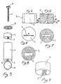
- - la fig. 3 est une vue en pièces détachées de ses composants importants;
- - la fig. 4 est une vue d'un piston adapté à ce dispositif;
- - la fig. 5 est une vue sectionnée du même piston;
- - la fig. 6 est une vue du haut du même piston;
- - la fig. 7 est la section sur le plan d'esquisse VII-VII;
- - la fig. 8 est la section VIII-VIII;
- - la fig. 9 est une perspective depuis le bas.
- Conformément à la présente invention, les figures citées ci-dessus se réfèrent à un exprimeur de pâte en tube qui comprend une enveloppe tubulaire cylindrique 1 avec le fond fermé 2 dans lequel peut glisser un piston 3 poussé vers ce fond 2 par la vis d'une presse 4 associée au centre d'un premier couvercle 5 vissé sur la même enveloppe 1 .
- Cette vis 4 , sur son extrêmité sortant de cette enveloppe 1 , est dotée d'une petite poignée 6 de manoeuvre.
- Ce piston 3 est pourvu en longeur d'une fente 7 adéquatement silhouettée selon une forme assimilable à un entonnoir courbe, fente dans laquelle est insérée la portion postérieure 8 d'un tube 9 contenant du dentifrice dont la portion antérieure 10 repose sur le fond 2 de ladite enveloppe 1 . L'extremité 11 du tube 9 sort par un trou 12 de ce fond 2 .
- La poussée de la vis 4 sur le piston 3 le fait descendre en sorte que les parois de la fente 7 exercent sur le tube 9 la pression nécessaire pour exprimer la pâte.
- A l'extérieur, cette enveloppe 1 est munie d'un appendice 13 apte à la fixation au mur par l'intermédiaire de vis, et d'une couronne 14 pourvue de trous 15 dans lesquels on peut insérer les brosses à dents 16 .
- A l'extérieur de ce fond 2 est fixé par une charnière un second couvercle 17 apte à protéger l'extrêmité 11 du tube 9 .
- Le pas de la vis 4 est calibré de façon qu'une petite rotation produise l'expulsion demandée.
- L'exacte courbure à conférer aux parois de la fente 7 est déterminable à travers quelques essais expérimentaux à partir de la configuration théorique illustrée dans la figure 5 .
- On effectue le chargement de la manière suivante: on in troduit le tube 9 renversé dans l'enveloppe 1 avec son extrêmité 11 saillant par le trou 12, ensuite on met le piston 3 en ayant soin d'insérer la portion postérieure 8 du tube 9 dans la fente 7 et, à la fin, on visse le couvercle 5 qui porte la vis 4.
- Cette invention, on peut la réaliser, en tout ou en partie, en matière plastique, toute autre matière appropriée pouvant cependant être utilisée.
- Il va sans dire que toutes les dimensions sont facultatives, suivant les exigences.
- L'invention ainsi conçue est susceptible de différents modes de réalisation ( outre ceux qui ont eté précédemment exposés ) et d'autres variantes, formes et modifications relevant toutes du principe de l'invention.
- En outre, on peut remplacer chaque élément par un autre élément techniquement équivalent; par exemple, on peut remplacer l'enveloppe tubulaire par un autre élément ayant les mêmes fonctions, comme par exemple une cage, même réduite à peu de barreaux.
- Le présent exprimeur de pâte en tube est, dans toutes ses formes, aisement réalisable dans l'industrie. On peut effectivement le fabriquer à des coûts réduits au moyen des installations usuelles; en particulier, on peut obtenir les parties en matière plastique par l'estampage par presse à injection thermoplastique.
Claims (7)
Priority Applications (1)
| Application Number | Priority Date | Filing Date | Title |
|---|---|---|---|
| AT88200319T ATE79814T1 (de) | 1987-09-28 | 1988-02-23 | Vorrichtung zum ausdruecken von pasten aus einer tube. |
Applications Claiming Priority (2)
| Application Number | Priority Date | Filing Date | Title |
|---|---|---|---|
| IT41686/87A IT1218805B (it) | 1987-09-28 | 1987-09-28 | Spremitore di pasta in tubetto |
| IT4168687 | 1987-09-28 |
Publications (3)
| Publication Number | Publication Date |
|---|---|
| EP0310146A2 true EP0310146A2 (fr) | 1989-04-05 |
| EP0310146A3 EP0310146A3 (en) | 1990-03-21 |
| EP0310146B1 EP0310146B1 (fr) | 1992-08-26 |
Family
ID=11253010
Family Applications (1)
| Application Number | Title | Priority Date | Filing Date |
|---|---|---|---|
| EP88200319A Expired - Lifetime EP0310146B1 (fr) | 1987-09-28 | 1988-02-23 | Exprimeur de pâte en tube |
Country Status (4)
| Country | Link |
|---|---|
| EP (1) | EP0310146B1 (fr) |
| AT (1) | ATE79814T1 (fr) |
| DE (1) | DE3874067T2 (fr) |
| IT (1) | IT1218805B (fr) |
Cited By (3)
| Publication number | Priority date | Publication date | Assignee | Title |
|---|---|---|---|---|
| RU2247689C1 (ru) * | 2004-03-19 | 2005-03-10 | Барский Борис Лейбович | Устройство для выдавливания пастообразного наполнителя из тюбика |
| CN104176367A (zh) * | 2014-08-15 | 2014-12-03 | 佛山市南方包装有限公司 | 可压实内容物的容器瓶 |
| CN104760749A (zh) * | 2015-04-16 | 2015-07-08 | 冯泰威 | 定量式推进牙膏桶 |
Families Citing this family (1)
| Publication number | Priority date | Publication date | Assignee | Title |
|---|---|---|---|---|
| DE102009029995A1 (de) * | 2009-06-23 | 2010-12-30 | Daniel Andrei | Tube und Entleervorrichtung |
Family Cites Families (5)
| Publication number | Priority date | Publication date | Assignee | Title |
|---|---|---|---|---|
| CH259056A (de) * | 1947-11-15 | 1949-01-15 | Aebersold Fritz | Apparat zum Kitten von Fensterscheiben und dergleichen. |
| US2528662A (en) * | 1948-06-30 | 1950-11-07 | John M Miller | Tooth paste dispenser having a cutoff valve actuated by a toothbrush |
| US2795356A (en) * | 1956-04-03 | 1957-06-11 | Tschumy De Leon | Ejecting device for collapsible tubes |
| US3687339A (en) * | 1970-10-12 | 1972-08-29 | Eloi Dessureault | Paste dispenser and disposable cartridge therefor |
| US3861567A (en) * | 1974-03-13 | 1975-01-21 | Davis George B Jun | Hand-held electric caulking gun |
-
1987
- 1987-09-28 IT IT41686/87A patent/IT1218805B/it active
-
1988
- 1988-02-23 DE DE8888200319T patent/DE3874067T2/de not_active Expired - Fee Related
- 1988-02-23 AT AT88200319T patent/ATE79814T1/de not_active IP Right Cessation
- 1988-02-23 EP EP88200319A patent/EP0310146B1/fr not_active Expired - Lifetime
Cited By (3)
| Publication number | Priority date | Publication date | Assignee | Title |
|---|---|---|---|---|
| RU2247689C1 (ru) * | 2004-03-19 | 2005-03-10 | Барский Борис Лейбович | Устройство для выдавливания пастообразного наполнителя из тюбика |
| CN104176367A (zh) * | 2014-08-15 | 2014-12-03 | 佛山市南方包装有限公司 | 可压实内容物的容器瓶 |
| CN104760749A (zh) * | 2015-04-16 | 2015-07-08 | 冯泰威 | 定量式推进牙膏桶 |
Also Published As
| Publication number | Publication date |
|---|---|
| EP0310146A3 (en) | 1990-03-21 |
| DE3874067T2 (de) | 1993-03-25 |
| IT8741686A0 (it) | 1987-09-28 |
| EP0310146B1 (fr) | 1992-08-26 |
| IT1218805B (it) | 1990-04-19 |
| ATE79814T1 (de) | 1992-09-15 |
| DE3874067D1 (de) | 1992-10-01 |
Similar Documents
| Publication | Publication Date | Title |
|---|---|---|
| FR2965460A1 (fr) | Applicateur cosmetique et contenant cosmetique | |
| FR2459022A1 (fr) | Accessoire de poche pour l'hygiene buccale, comprenant dans un etui une brosse a dents et un recipient ou tube de dentifrice | |
| EP0310146B1 (fr) | Exprimeur de pâte en tube | |
| FR2517184A1 (fr) | Element prolongateur pour le roulage et/ou le portage d'un bagage a main | |
| EP0573840B1 (fr) | Bâton d'alun fixé dans un étui | |
| FR2702172A1 (fr) | Tournevis muni de logements pour des embouts interchangeables. | |
| EP0274960B1 (fr) | Cartouche réservoir d'encre pour stylographe rechargeable et procédé de fabrication d'une telle cartouche | |
| FR2690327A1 (fr) | Dispositif de liaison amovible et d'articulation d'une assise et/ou d'un couvercle sur une cuvette de W.C.. | |
| FR2650563A1 (fr) | Obturateur a mouvement vertical pour recipients divers | |
| FR2537856A1 (fr) | Brosse a dents | |
| FR2656202A1 (fr) | ||
| FR2575649A1 (fr) | Melangeur electrique equipe d'un mecanisme ejecteur de batteurs | |
| EP0026180A1 (fr) | Douche a main | |
| FR2664480A1 (fr) | Conteneur de produit cosmetique du type a percussion. | |
| WO2000061488A2 (fr) | Ensemble (bouchon-outil) pour ouvrir | |
| WO1999060887A1 (fr) | Brosse a dents a reservoir | |
| EP3027080A2 (fr) | Applicateur pour produit cosmétique et ensemble applicateur | |
| WO1995024841A1 (fr) | Dispositif applicateur rechargeable d'un produit liquide plus ou moins visqueux | |
| FR2474842A1 (fr) | Etui pour brosse a dents, muni d'un moyen d'ejection partielle de la brosse | |
| CH464004A (fr) | Dispositif pour étaler sur une surface un produit contenu dans un récipient | |
| WO1995001933A1 (fr) | Dispositif pour l'ouverture d'une bouteille a capsule a couronne | |
| CH695775A5 (fr) | Bouchon-verseur pour récipient. | |
| BE526405A (fr) | ||
| BE379470A (fr) | Perfectionnements aux brosses à alimentation automatique | |
| FR2684526A1 (fr) | Boitier de maquillage contenant de la poudre compactee. |
Legal Events
| Date | Code | Title | Description |
|---|---|---|---|
| PUAI | Public reference made under article 153(3) epc to a published international application that has entered the european phase |
Free format text: ORIGINAL CODE: 0009012 |
|
| AK | Designated contracting states |
Kind code of ref document: A2 Designated state(s): AT BE CH DE ES FR GB GR IT LI NL SE |
|
| PUAL | Search report despatched |
Free format text: ORIGINAL CODE: 0009013 |
|
| AK | Designated contracting states |
Kind code of ref document: A3 Designated state(s): AT BE CH DE ES FR GB GR IT LI NL SE |
|
| 17P | Request for examination filed |
Effective date: 19900904 |
|
| 17Q | First examination report despatched |
Effective date: 19910903 |
|
| GRAA | (expected) grant |
Free format text: ORIGINAL CODE: 0009210 |
|
| AK | Designated contracting states |
Kind code of ref document: B1 Designated state(s): AT BE CH DE ES FR GB GR IT LI NL SE |
|
| PG25 | Lapsed in a contracting state [announced via postgrant information from national office to epo] |
Ref country code: IT Free format text: LAPSE BECAUSE OF FAILURE TO SUBMIT A TRANSLATION OF THE DESCRIPTION OR TO PAY THE FEE WITHIN THE PRE;WARNING: LAPSES OF ITALIAN PATENTS WITH EFFECTIVE DATE BEFORE 2007 MAY HAVE OCCURRED AT ANY TIME BEFORE 2007. THE CORRECT EFFECTIVE DATE MAY BE DIFFERENT FROM THE ONE RECORDED.SCRIBED TIME-LIMIT Effective date: 19920826 Ref country code: GR Free format text: LAPSE BECAUSE OF FAILURE TO SUBMIT A TRANSLATION OF THE DESCRIPTION OR TO PAY THE FEE WITHIN THE PRESCRIBED TIME-LIMIT Effective date: 19920826 Ref country code: GB Effective date: 19920826 Ref country code: AT Effective date: 19920826 Ref country code: NL Effective date: 19920826 Ref country code: SE Free format text: THE PATENT HAS BEEN ANNULLED BY A DECISION OF A NATIONAL AUTHORITY Effective date: 19920826 Ref country code: ES Free format text: THE PATENT HAS BEEN ANNULLED BY A DECISION OF A NATIONAL AUTHORITY Effective date: 19920826 |
|
| REF | Corresponds to: |
Ref document number: 79814 Country of ref document: AT Date of ref document: 19920915 Kind code of ref document: T |
|
| REF | Corresponds to: |
Ref document number: 3874067 Country of ref document: DE Date of ref document: 19921001 |
|
| NLV1 | Nl: lapsed or annulled due to failure to fulfill the requirements of art. 29p and 29m of the patents act | ||
| PG25 | Lapsed in a contracting state [announced via postgrant information from national office to epo] |
Ref country code: CH Effective date: 19930228 Ref country code: LI Effective date: 19930228 Ref country code: BE Effective date: 19930228 |
|
| PGFP | Annual fee paid to national office [announced via postgrant information from national office to epo] |
Ref country code: DE Payment date: 19930301 Year of fee payment: 6 |
|
| GBV | Gb: ep patent (uk) treated as always having been void in accordance with gb section 77(7)/1977 [no translation filed] |
Effective date: 19920826 |
|
| PLBE | No opposition filed within time limit |
Free format text: ORIGINAL CODE: 0009261 |
|
| STAA | Information on the status of an ep patent application or granted ep patent |
Free format text: STATUS: NO OPPOSITION FILED WITHIN TIME LIMIT |
|
| 26N | No opposition filed | ||
| BERE | Be: lapsed |
Owner name: TROVO FEDERICO Effective date: 19930228 |
|
| REG | Reference to a national code |
Ref country code: CH Ref legal event code: PL |
|
| PG25 | Lapsed in a contracting state [announced via postgrant information from national office to epo] |
Ref country code: DE Effective date: 19941101 |
|
| PGFP | Annual fee paid to national office [announced via postgrant information from national office to epo] |
Ref country code: FR Payment date: 19950216 Year of fee payment: 8 |
|
| PG25 | Lapsed in a contracting state [announced via postgrant information from national office to epo] |
Ref country code: FR Effective date: 19961031 |
|
| REG | Reference to a national code |
Ref country code: FR Ref legal event code: ST |