EP0310360B1 - Verfahren und Vorrichtung zur Datenübertragung - Google Patents
Verfahren und Vorrichtung zur Datenübertragung Download PDFInfo
- Publication number
- EP0310360B1 EP0310360B1 EP88309000A EP88309000A EP0310360B1 EP 0310360 B1 EP0310360 B1 EP 0310360B1 EP 88309000 A EP88309000 A EP 88309000A EP 88309000 A EP88309000 A EP 88309000A EP 0310360 B1 EP0310360 B1 EP 0310360B1
- Authority
- EP
- European Patent Office
- Prior art keywords
- information
- frame
- input
- frames
- link
- Prior art date
- Legal status (The legal status is an assumption and is not a legal conclusion. Google has not performed a legal analysis and makes no representation as to the accuracy of the status listed.)
- Expired - Lifetime
Links
- 238000000034 method Methods 0.000 title claims description 29
- 230000006854 communication Effects 0.000 title claims description 19
- 238000004891 communication Methods 0.000 title claims description 19
- 239000000872 buffer Substances 0.000 claims description 45
- 230000005540 biological transmission Effects 0.000 claims description 24
- 238000012546 transfer Methods 0.000 claims description 14
- 230000000295 complement effect Effects 0.000 claims description 8
- 230000006870 function Effects 0.000 claims description 8
- 230000008878 coupling Effects 0.000 claims description 7
- 238000010168 coupling process Methods 0.000 claims description 7
- 238000005859 coupling reaction Methods 0.000 claims description 7
- 230000002457 bidirectional effect Effects 0.000 claims description 5
- 230000004044 response Effects 0.000 claims description 3
- 230000000694 effects Effects 0.000 claims 1
- 230000008901 benefit Effects 0.000 description 8
- 238000001514 detection method Methods 0.000 description 6
- 239000000835 fiber Substances 0.000 description 5
- 238000011084 recovery Methods 0.000 description 5
- 238000007726 management method Methods 0.000 description 4
- 230000008569 process Effects 0.000 description 4
- 238000010586 diagram Methods 0.000 description 3
- 230000007246 mechanism Effects 0.000 description 3
- 230000004048 modification Effects 0.000 description 3
- 238000012986 modification Methods 0.000 description 3
- 230000001360 synchronised effect Effects 0.000 description 3
- 230000009471 action Effects 0.000 description 2
- 230000006399 behavior Effects 0.000 description 2
- 230000003139 buffering effect Effects 0.000 description 2
- 238000012937 correction Methods 0.000 description 2
- 125000004122 cyclic group Chemical group 0.000 description 2
- 238000009432 framing Methods 0.000 description 2
- 230000009467 reduction Effects 0.000 description 2
- 108010046315 IDL Lipoproteins Proteins 0.000 description 1
- 101100172132 Mus musculus Eif3a gene Proteins 0.000 description 1
- 230000007175 bidirectional communication Effects 0.000 description 1
- 230000008859 change Effects 0.000 description 1
- 238000006243 chemical reaction Methods 0.000 description 1
- 238000013501 data transformation Methods 0.000 description 1
- 230000003111 delayed effect Effects 0.000 description 1
- 238000011161 development Methods 0.000 description 1
- 238000005538 encapsulation Methods 0.000 description 1
- 238000005516 engineering process Methods 0.000 description 1
- 239000000284 extract Substances 0.000 description 1
- 230000003993 interaction Effects 0.000 description 1
- 230000006855 networking Effects 0.000 description 1
- 239000013307 optical fiber Substances 0.000 description 1
- 230000008520 organization Effects 0.000 description 1
- 238000004904 shortening Methods 0.000 description 1
- 230000011664 signaling Effects 0.000 description 1
- 238000012360 testing method Methods 0.000 description 1
- 230000001131 transforming effect Effects 0.000 description 1
Images


Classifications
-
- H—ELECTRICITY
- H04—ELECTRIC COMMUNICATION TECHNIQUE
- H04L—TRANSMISSION OF DIGITAL INFORMATION, e.g. TELEGRAPHIC COMMUNICATION
- H04L1/00—Arrangements for detecting or preventing errors in the information received
- H04L1/12—Arrangements for detecting or preventing errors in the information received by using return channel
- H04L1/16—Arrangements for detecting or preventing errors in the information received by using return channel in which the return channel carries supervisory signals, e.g. repetition request signals
- H04L1/18—Automatic repetition systems, e.g. Van Duuren systems
- H04L1/1867—Arrangements specially adapted for the transmitter end
- H04L1/187—Details of sliding window management
-
- H—ELECTRICITY
- H04—ELECTRIC COMMUNICATION TECHNIQUE
- H04L—TRANSMISSION OF DIGITAL INFORMATION, e.g. TELEGRAPHIC COMMUNICATION
- H04L47/00—Traffic control in data switching networks
- H04L47/10—Flow control; Congestion control
-
- H—ELECTRICITY
- H04—ELECTRIC COMMUNICATION TECHNIQUE
- H04L—TRANSMISSION OF DIGITAL INFORMATION, e.g. TELEGRAPHIC COMMUNICATION
- H04L47/00—Traffic control in data switching networks
- H04L47/10—Flow control; Congestion control
- H04L47/22—Traffic shaping
- H04L47/225—Determination of shaping rate, e.g. using a moving window
-
- H—ELECTRICITY
- H04—ELECTRIC COMMUNICATION TECHNIQUE
- H04L—TRANSMISSION OF DIGITAL INFORMATION, e.g. TELEGRAPHIC COMMUNICATION
- H04L47/00—Traffic control in data switching networks
- H04L47/10—Flow control; Congestion control
- H04L47/30—Flow control; Congestion control in combination with information about buffer occupancy at either end or at transit nodes
-
- H—ELECTRICITY
- H04—ELECTRIC COMMUNICATION TECHNIQUE
- H04L—TRANSMISSION OF DIGITAL INFORMATION, e.g. TELEGRAPHIC COMMUNICATION
- H04L1/00—Arrangements for detecting or preventing errors in the information received
- H04L1/12—Arrangements for detecting or preventing errors in the information received by using return channel
- H04L1/16—Arrangements for detecting or preventing errors in the information received by using return channel in which the return channel carries supervisory signals, e.g. repetition request signals
- H04L1/1607—Details of the supervisory signal
- H04L1/1657—Implicit acknowledgement of correct or incorrect reception, e.g. with a moving window
-
- H—ELECTRICITY
- H04—ELECTRIC COMMUNICATION TECHNIQUE
- H04L—TRANSMISSION OF DIGITAL INFORMATION, e.g. TELEGRAPHIC COMMUNICATION
- H04L69/00—Network arrangements, protocols or services independent of the application payload and not provided for in the other groups of this subclass
- H04L69/30—Definitions, standards or architectural aspects of layered protocol stacks
- H04L69/32—Architecture of open systems interconnection [OSI] 7-layer type protocol stacks, e.g. the interfaces between the data link level and the physical level
- H04L69/322—Intralayer communication protocols among peer entities or protocol data unit [PDU] definitions
- H04L69/324—Intralayer communication protocols among peer entities or protocol data unit [PDU] definitions in the data link layer [OSI layer 2], e.g. HDLC
Definitions
- the present invention generally relates to data communications, such as local area networks (LAN) and, more particularly, to a method and apparatus for controlling the transmission across a data link.
- LAN local area networks
- DTE data terminal equipment
- the physical transfer is accomplished by data buffering, where anywhere from approximately 128 to 4096 bytes may be buffered (the physical media may limit the maximum, e.g. Ethernet/IEEE 802.3 is limited to 1514 bytes per transferred data field).
- Packets have different parts. Delimiters mark the start and end of a packet, framing the packet. They are also used to synchronize the transmitter and receiver sections of the DTEs on the link. Frame structure is concerned with defining each unit of information transferred across a data link. Typically there are control frames (C-FRAMES) for link management and information frames (I-FRAMES) for the transfer of user's message data. Typical information frames and control frames are shown in FIGURES 5a and 5b, respectively.
- the header at the beginning of a packet identifies the type of packet information, viz. control or data. Data packets contain the user's data (as opposed to data which the protocol understands). Control packets relate to information established by the protocol.
- Protocols are generally organized into layers, each layer operating more or less independently.
- OSI open systems interconnection
- FIGURE 1 a seven layer standard, shown in FIGURE 1 , has been adopted to make multi-vendor networking products easier to accomplish.
- the types of frames and messages used by each layer vary since they each perform different and complementary functions.
- a higher level software layers communicate over the link by exchanging messages using the resources provided by lower layers.
- Link Layer protocol is concerned with providing reliable transmission on the data link, viz., providing a reliable transport facility across the physical transmission media link between DTEs.
- Important components of a Link Level protocol are connection management, error control and flow control.
- Error control is concerned with both error detection and correction.
- the quantum of recovery is a packet. Error detection is usually determined by using a Cyclic Redundancy Check (CRC in FIGURES 5a and 5b), a numeric value computed from the data in the message transmitted which is compared to the value generated from the data received. Error recovery is achieved by rejection of the bad packet by the receiving DTE node on the link and retransmission from the transmitting DTE node on the link.
- CRC Cyclic Redundancy Check
- Flow control is concerned with controlling the rate of transmission of elements - characters or frames of characters - on a link. Transmission and reception are generally asynchronous processes. Therefore, flow control is necessary so that the receiver always has sufficient buffer storage resources to accept each element sent to it, i.e. to prevent the transmitter from overrunning the receiver.
- the common means for achieving flow control is by using "start" and "stop" control messages.
- a Link Layer protocol can be considered as being concerned with several intricacies of communicating over a link: first, with the initial setting up of the link to ensure both parties are ready to exchange information, second, with the ordered exchange of data blocks or messages across the link, and third, with the orderly release or clearing of the link.
- the present invention relates to the first and second. A number of control messages are needed to perform the various functions.
- Link Layer protocol for bidirectional transmission on a link
- the essence of all sliding window protocols is that at any instant of time, the transmitting node maintains a list of consecutive sequence numbers corresponding to frames it is permitted to send. These frames are said to fall within the sending window. Similarly, the receiving node also maintains a receiving window corresponding to frames it is permitted to accept.
- the protocol is required to deliver the messages to the destination DTE in the same order they were passed from the source DTE. Since frames currently within the sender's window may ultimately be lost or damaged in transit, the sender must keep all these frames in its memory for possible retransmission. Thus, the sequence numbers of the transmitted frames within the sender's window represent frames sent but not acknowledged.
- the present invention relates to a component of a data communication equipment (DCE) - for example, a backplane input-output adapter - which establishes and maintains Link Level protocol for the local DTE coupled to a communication link through the adapter.
- DCE data communication equipment
- the present invention provides a method and apparatus for improving the performance of the data flow in a high speed data link.
- the present invention provides an advantage of allowing implementation in a single integrated circuit chip, hence, lowering the cost of a link connection and increasing its mean time between failure (MTBF).
- MTBF mean time between failure
- Yet a further advantage of the present invention is that full error detection and correction and flow control are provided at the Link Layer level.
- a further advantage of the present invention is that it provides simultaneous bidirectional communication.
- Another advantage of the present invention is that it provides continuous, bidirectional flow of information frames without requiring an interrupt to send flow control frames.
- Another advantage of the present invention is that it provides data link error and flow control on a single integrated circuit chip using relatively small buffers.
- Still another advantage of the present invention is that it provides flow and error control frames, using instruction bits in said frames (rather than requiring separate frames for each control instruction) and operating as headers in both I-FRAMES and C-FRAMES.
- the present invention includes a method for controlling data transmission using an open systems interconnection model as defined by claim 1.
- the present invention provides in data communication equipment, a protocol controller device as defined by claim 15.
- FIGURE 1 (prior art) is a depiction of the OSI data encapsulation protocol standard.
- FIGURE 2 is a depiction of a typical pattern of a stream of information flow on a communication link as implemented in accordance with the present invention.
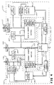
- FIGURE 3 is a schematic block diagram depicting the overall structure of the apparatus of the present invention.
- FIGURE 4 is a preferred embodiment schematic block diagram of the apparatus of the present invention as shown in FIGURE 3 as implemented in a single integrated circuit architecture.
- FIGURES 5a-5d are depictions of transmission frames in which:
- FIGURE 5a (prior art) is a depiction of two formats of information data frames in a communication link flow pattern such as shown in FIGURE 2;
- FIGURE 5b (prior art) is a depiction of a control data frame as may be found in a communication link flow pattern such as shown in FIGURE 2;
- FIGURE 5c is a depiction of an information data frame header according to the method of the present invention.
- FIGURE 5d is a depiction of a control data frame header according to the method of the present invention.
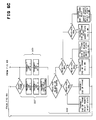
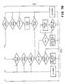
- FIGURE 6a-6c is a flow chart representation according to the present invention of a state machine for establishing data flow in the TRANSMIT mode.
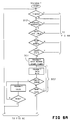
- FIGURE 7a-7b is a flow chart representation according to the present invention of the state machine for establishing data flow in the RECEIVE mode.
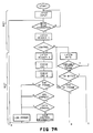
- FIGURE 8a is a flow chart representation according to the present invention of the state machine for ACKNOWLEDGE data frames.
- FIGURE 8b is a depiction of an example of ACKNOWLEDGE state variable buffer region pointer operation as shown in shown in FIGURE 8a.
- FIGURES 9a, 9b and 9c are flow charts according to the present invention of the state machine for establishing internal synchronization conditions.
- the apparatus may be constructed in integrated circuit (IC) form and, more specifically, as a single IC chip. As such, however, a detailed description of the particular circuitry or process technology in an IC implementation is not necessary to an understanding of the inventive concept disclosed herein.
- IC integrated circuit
- FIGURE 2 A typical flow of information across a link in accordance with the present invention is shown in FIGURE 2.
- IDL idle symbol
- BSC byte synchronization character
- the device 101 (referred to hereinafter as protocol controller 101), is responsible for transforming data to and from the Link Layer protocol format.
- the protocol controller 101 can be one component of an input-output (I/O) card device for a computer in which it couples input/output bus backplane adapter and microprocessor components (not shown), which receive information from a local host DTE, to an output component (not shown), such as a parallel-to-serial converter (PSC), which is coupled to the communication link.
- I/O input-output
- PSC parallel-to-serial converter
- the protocol controller 101 is presented as part of an I/O card coupling a local host DTE to a fiber optic communication link (not shown).
- an identical, or compatible, data communication equipment having a complementary adapter is available at a remote node on the link. It is not the intent of the inventors that the scope of the invention be limited by this example.
- the protocol controller 101 establishes and maintains Link Level protocol for the DTE which is coupled to a communication link through the I/O card.
- the actual protocol control takes place in the management of data that are sent and received by the protocol controller 101.
- the protocol formatting is a variation of a Link Layer "sliding-window" protocol.
- I/O port controllers provide bidirectional capability through the ports 103, 117, 119.
- the protocol controller 101 provides both a half-duplex and full-duplex interface. Data to be transformed to the protocol format by the protocol controller 101 and then transmitted is received via a bus from another system component, such as an I/O bus adapter device (not shown).
- a control port controller 107 is used, such as by a related processor component (not shown), to access control registers and to transfer data to and from the link, in this embodiment, for example, via the RX port 117 and the TX port 119 coupled to a fiber optic conversion unit.
- the control port controller 107 comprises registers and a programmable logic array used to control and monitor the behavior of the link and data transfers active on it. Some error conditions and recovery measures are managed through this path.
- Data transfers via the control port controller 107 usually consist of header messages (described in detail hereinafter) - viz. those used to setup and execute data transfers between a local I/O card or DTE and a complementary remote device - which would follow the Network Layer 3 protocol as shown in FIGURE 1. Timing control is specific to each commercial embodiment designed. Hence, only general reference will be given throughout this description.
- the device port controller 111 establishes a high speed direct access port which handles the majority of the I/O traffic on the link. It provides a direct data path to inbound, RX, or outbound, TX, memory components 113, 115, depending upon the direction of the data transfer. Status indicators are provided via the port 103 to indicate whether the device port controller 111 is ready to send or receive data as well as to identify when a particular stream of data has reached a termination condition. Again, timing is device specific.
- control port controller 107 and device port controller 111 can be implemented as a single register 103′ controlled by the microprocessor.
- Both the paths for inbound link data, RX DATA from the RX port 117, and outbound link data, TX DATA to the TX port 119 contain memory, in the present embodiment, an addressable first-in, first-out (FIFO) memory component 113, 115, respectively.
- FIFO first-in, first-out
- the protocol controller 101 In the case of data in the outbound (TX memory) FIFO 115, the protocol controller 101 must guarantee that any data (TX data) loaded into the FIFO 115 will not be overwritten until it has been correctly received by the remote node device on the link and, furthermore, that the inbound FIFO of the remote node controller (not shown) will not be overrun.
- the protocol controller 101 For inbound data, RX DATA from the RX port 117, the protocol controller 101 must guarantee that all data have been received in the order it was loaded into the remote node's outbound FIFO and that any attempts at overrun will generate a protocol error.
- a receive port controller 121 take parallel data from the RX port 117, processes it, verifies its integrity, and then extracts the protocol Link Layer 2 information from it.
- Valid data extracted from I-FRAMES - consisting of formatted buffers obtained from the outbound FIFO 115, involving prefacing the buffer of data with an information header which identifies the particular buffer to be sent and then appending a CRC to the buffer to protect the data buffer's content - are loaded into the inbound FIFO 113.
- Remote node state information is extracted from I-FRAMES and C-FRAMES - containing the current state of the inbound FIFO 113 as well as link control commands - and directs behavior of a transmit port controller 123.
- the receive port controller 121 also monitors the state of the fiber optic converter unit's receiver and provides this information to the related microprocessor via the control port controller 107.
- the transmit port controller 123 is used by the protocol controller 101 to send data from the outbound FIFO 115 to the link via the TX port 119 to the fiber optic converter unit's transmitter. It also supplies state information to the remote node to allow management of the link via the Link Layer 2 protocol. Data and state information are packaged in the I-FRAMES and C-FRAMES, respectively.
- the protocol controller 101 must determine the state of the remote node's inbound FIFO from data received through the receive port controller 121. C-FRAMEs are sent if the protocol controller 101 is incapable of currently sending an I-FRAME. Acknowledgement of outstanding buffers and transmissions retry is also caused by examination of the state of the remote node's inbound FIFO by the transmit port controller 123.
- a special feature of the present embodiment are switch components 125, 127. These switch components 125, 127 allow the inbound and outbound data paths to be either manually or automatically pointed to the device port controller 111 or the control port controller 107. Each FIFO 113, 115 has its own independent switch 125, 127, respectively. When the switches 125, 127 are manually operated, an associated processor explicitly can establish the connection to the I/O data paths by pointing the switch to one of the port controllers 107, 111. In an automatic mode, each switch 125, 127 toggles between the control port controller 107 and device port controller 111, depending upon information previously loaded into the control port controller register 103. The switch feature only affects data transfer paths; it does not inhibit control port controller register 103 accesses.
- Timing control can be implemented by generating two internal, non-overlapping clock signals using an external system clock input 102.
- Another external clock input 118 signal is used for TRANSMIT MODE of operation.
- Still another external clock input signal 116 is used for RECEIVE MODE of operation.
- Some signals must provide communication between the RECEIVE and TRANSMIT clock domains. To accomplish this, these signals are first synchronized to the system clock domain signal 102 and then to the TRANSMIT clock domain 118.
- the internal system clock frequency is twice that of the external system clock input 102, allowing four clock phases to be generated per external system clock cycle.
- FIGURE 4 shows an exemplary, single-chip, LSI integrated circuit block diagram implementation of the above-described device.
- the apparatus generally can be thought of as operating as a state machine.
- Both the TRANSMIT and RECEIVE sections of the controller 101 have CRC circuitry.
- the transmit CRC Generator 201 monitors the data stream and maintains a running CRC. A START signal will clear the CRC register at the beginning of each frame. The contents of the upper half of the CRC register is gated onto the data bus during the two clock cycles following the data. These two bytes represent the contents of the CRC register after the last data byte was clocked in.
- the receive CRC Checker 203 also maintains a running CRC and is reset at the start of each frame just like the transmit CRC Generator 201. It also maintains a running comparison of received data and the contents of its CRC register during the last two clock cycles. Matching of received CRC and locally computed CRC can thereby be accomplished.
- common parity generation and checking 205, 207 is also provided if required by the overall system.
- the protocol mechanism of the present invention has several features which provide for improved data transmission.
- Reductions are made to the size of the data portion of information packets.
- the shortening of the length of data within an information packet allows on-chip buffering. This increases link speed by giving faster access to the data.
- Discrete bits in the packet headers are used for both information and control packet types.
- the control packet headers as shown in FIGURES 5C and 5D , use distinct bits to enumerate the packet type (instead of encoding the bits within each field as shown in FIGURE 5B ).
- the independence of the distinct bits also allows the simultaneous sending of several control flags. This reduces the number of control packets sent, thereby increasing link throughput.
- Reductions are made in the number of types of packets and the size of their headers.
- the number of packet types has been reduced to two (from the traditional three).
- the information packet header size is reduced from two bytes to one byte.
- a third state variable, Ve is added to the traditional two, Vs and Vr, in the packet header.
- the addition of Ve allows the transmitting DTE to know how much information it can send without overrunning the receiving DTE.
- FIGURES 6 through 9 are flow charts showing the basic state machine control functions performed in the data transformation to and from the protocol format implemented by the present invention.
- Data are loaded into the transmit memory FIFO 133 per the control direction provided by the microcode of the host PLA 131 receive section.
- a full sixteen byte buffer is loaded unless there is a higher level end-of-segment (EOS) in the Direct Memory Access (DMA) Control Register, indicating a shorter buffer needs to be sent 507.
- EOS End-of-segment
- DMA Direct Memory Access
- the host transmit PLA 131 sets a signal, TX_Full[X], indicating that the buffer is available.
- the information includes a count indicating how many bytes are valid.
- the controller 101 will drive a PSC transmit data bus and control with signals generated every transmit clock cycle.
- the controller 101 will insert a BSC at the beginning of each frame, a CRC after the body of each frame, a VLF after the CRC if necessary to indicate a short data frame, and an EOF at the end of each frame.
- the controller 101 will drive an IDL signal after a reset and before and after entering a loop back mode and if a parity error is encountered.
- a TRANSMIT control PLA 135 sends user information by sending I-FRAMEs.
- PLA 135 sends control information in C-FRAMEs.
- C-FRAME transmission occurs when: there is new control information, there is an outstanding RSN, there is an outstanding QRY, there is an outstanding RLR, or an I-FRAME cannot be sent.
- the TRANSMIT MODE is required to transmit a C-FRAME whenever any of the control flag bits, REJ, QRY, QRS, RSN, RSA, RLR, or RRA are set.
- These C-FRAMEs have precedence 513 over I-FRAMEs. Since all of the bits which are set are carried with the C-FRAME, only one frame needs to be sent when more than one bit is set. All bits which were transmitted in the control fame are cleared when the frame is sent. When there are no I-FRAMEs ready to send (or the transmit window is closed), C-FRAMEs provide updates to the remote as to the state of the local receiver.
- I-FRAME transmission will occur when: there is valid data in the memory to be sent and the transmit window is open and none of the first three reasons for sending a C-FRAME are true.
- the link TRANSMIT control PLA 135 transmits the data out of the memory 133 if there is space available at the other end of the link, i.e. whenever the transmit window is open 509.
- the PLA 135 prefixes data with a header containing the buffer number of the buffer being sent, NS, and the buffer number of the I-FRAME that the local receiver expects to empty next, NE.
- the data are followed with a 16-bit CRC used for error detection, and the special character, VLF, if the frame is less than 16-bytes.
- the transmit window is open when the number of outstanding frames is one less than the number of buffers available, or equivalently, when the transmit sequence variable, VS, is not adjacent to the transmit window variable, VW (i.e., VS+1 ⁇ >VW).
- VW transmit window variable
- the send state variable, VS is incremented whenever a frame is transmitted.
- the transmitter manages the window state variable, VW, based on the receive and empty sequence numbers, NR and NE, respectively, in the frames received, and may modify VS to cause re-transmission in the case of an error.
- IDL transmission occurs: after a RST, before entering or leaving a loopback mode, JLB, after entering or leaving JLB, and when a parity error occurs.
- the transmit state machine will immediately begin transmitting IDLs on the link which will guarantee that the remote end will not interpret the data as valid.
- the controller 101 will generate an interrupt to the local microprocessor and will wait for a rest signal before transmitting anymore C-FRAMEs or I-FRAMEs.
- the transmit state machine will send: a BSC, the two bytes of control information (control headers), and two bytes of CRC followed by an EOF.
- the transmit state machine sends: a BSC, one byte of header information, the user data, VLF (if there were not sixteen bytes transmitted, and an EOF.
- the link level protocol requires a timer at each DTE for use in recovering from lost frames.
- the timer is fixed in duration at 256-byte times (for a one km link length, speeds to 120 megabaud, and frame sizes up to 16-bytes of data).
- the timer must be able to be restarted for the full duration or cleared (disabled) at any time.
- the timer is always left running whenever there are any unacknowledged I-FRAMEs within the transmit window, i.e. whenever VS ⁇ >VA, or there is an outstanding QRY or RLR. Expiration of the timer signals the sending of a QRY to the remote DTE to detect lost frames or acknowledge signals or retransmission of QRY or RLR in the event of no response.
- protocol controller 101 thus is providing error control at the Link Layer level in the TRANSMIT MODE. Moreover, the protocol controller 101 of the present invention also provides flow control 511 in the TRANSMIT MODE.
- the RECEIVE MODE is another state machine operation.
- the receive state machine checks the incoming frames and, if the CRC is correct; the number of bytes is correct; no link errors occurred; and the frame sequence is correct on I-FRAMES, it latches data either in the appropriate register within the link receive control PLA 139 for C-FRAMEs or in the appropriate buffer in memory 137 for I-FRAMEs.
- the serial-to-parallel converter receive data bus will be read by the controller 101 every receive clock cycle.
- the five control bytes (IDL, BSC, CRC, VLF, and EOF) and data will be removed from the body of the frame. If any error bits are set, the data is ignored and an error is logged to a link error counter in the host memory stack.
- Data are loaded into a receive memory FIFO 135 under microcode control of the link receive control PLA 139.
- the most significant bit of the first byte of a received frame informs 601 the protocol controller 101 whether it is an I-FRAME or a C-FRAME.
- the value of NE which was received in the header is passed to the link transmit control PLA 135 to be used for determining if there is space for data at the other end of the link. This is also only sent if the above three conditions were met.
- I-FRAMEs are assembled 605 in the buffer pointed to by VR until an EOF is received from the Physical Layer control.
- a CRC is computed as the bytes are received, and checked for agreement with the received CRC when the frame ends. In the preferred embodiment, it is intended to detect any two errors on the line in order to achieve a satisfactory rate of undetected errors.
- the state of the CRC register at any time represents the current remainder.
- the final state of the CRC register which is the final remainder, becomes the frame check word (FCW) and is appended to the data.
- FCW frame check word
- the receiver uses the entire received sequence including the FCW as the dividend. Barring any errors, the remainder at the receiver will be zero because the remainder at the transmitter was used as the FCW.
- the CRC register is initialized to one, the remainder is inverted before transmitting, and the receiver checks for a constant remainder when there are no errors.
- the preferred embodiment uses a circuit in which the state of the CRC register does not represent the current remainder. The input and output sequences, however, are identical (the same division is performed). Consequently, the FCW is not the remainder, and therefore, the receiver cannot include it in the division. The FCW is merely a "signature" which the receiver recomputes and verifies. In this implementation the initial and final contents of the CRC register are not equal so that the absence of a frame delimiter will be detected.
- the RX_FULL (Vr) bit is set for a filled buffer to allow the receive DMA to empty the buffer.
- the length of the frame, counted as bytes were received, is stored in the RX_CNTR for that buffer and VR is incremented.
- the protocol controller 101 also processes 607 incoming C-FRAMEs, thereby providing RECEIVE MODE flow control and error recovery at the Link Layer level.
- C-FRAMES are disassembled into two 8-bit latches, CL1 and CL2. If the CRC computed as the frame was received is not equal to the received CRC, or if there were link errors associated with the frame, the frame is discarded without further action. If the CRC matches, the functions indicated by the various bits in the latches are executed as follows:
- Re-synchronization occurs on power-up or any time that two protocol controllers 101 get out of sync during operation.
- the state variables of the receiving DTE protocol controller 101 are synchronized with those of the transmitting DTE protocol controller 101.
- Sending a C-FRAME with the RSN bit set causes the receiving DTE to set RSS and clear all counters and flags.
- Receiving RSN or RSA causes an interrupt to be sent to the microprocessor.
- Sending or receiving RSA clears RSS. While RSS is set, any received I-FRAME is discarded, and received C-FRAMEs are only processed for RSN, RSA, RLR, and RRA.
- the RLR function provides a low level signalling capability across a link and can be used when normal data communication does not seem to be working. The intent is that this signal be used to reset the remote DTE.
- the transmitting DTE asserts RLR in a C-FRAME sent to the remote DTE.
- the remote protocol controller 101 acknowledges receipt of the RLR by returning an RRA frame and then sends a pulse to the RLR pin on the receiving protocol controller 101.
- This dedicated pin can be sensed by whatever circuitry may need to be reset.
- the pulse on the RLR pin is delayed until after the RRA is sent, in case the reset affects the protocol controller itself.
- the RLR pin will be de-asserted if the protocol controller 101 is reset.
- TABLE II shows an example of a data transfer showing the interaction of the various state variables in controlling flow, and recovering from link errors. Note that only one half-duplex channel is shown. Since the protocol is symmetrical, the operation for the reverse channel is the same. Some of the sequences of actions (e.g., sending of frames and the transfer of information to the hosts, have been stretched to better show the operation of the transmit window, timer, and rejecting of out of sequence frames.
- TABLE II shows that after a RSN, all pointers are set to zero (1).
- the transmitter transmits frame zero (2), it updates VS to one and, when the frame is received properly, the remote updates VR to one (3). The same happens for frame one (4, 5).
- the remote then returns a C-FRAME (6), indicating the new value of VR which acknowledges frames zero and one and moves VS to two (7).
- the window is not changed since the remote did not change VE.
- Frame seven is then transmitted but has an error in transmission (15). The fact that frame seven was transmitted closes the window (16). But, since there was an error in this part of the example, there will not be an acknowledge.
- the transmitter timer will expire (17), causing a QRY to be transmitted (18).
- the QRS from the remote will indicate that the next frame expected is frame seven (20).
- the local device will then reset VS to seven and retransmit frame seven (21, 22).
- the window is then closed (23). Frames one through five are then read by the remote host DTE (24).
- Frame zero is then transmitted and an exemplary error is assumed to occur during its receipt (27). This means that VS is updated but VR is not (28). Frame one is then sent with no error (29). VS is again updated (30).
- the remote detects a good frame but out of sequence. It discards the frame and sets a reject state and sends REJ (30). Frame two is then transmitted at the same time as the REJ is sent from the remote (31-33). Frame two is discarded due to being out of sequence (31).
- the local resets VS 0 as indicated by the REJ (34) and begins by retransmitting frame zero (35).
- the reject state of the remote is cleared and normal operation is resumed (36-38).
Landscapes
- Engineering & Computer Science (AREA)
- Computer Networks & Wireless Communication (AREA)
- Signal Processing (AREA)
- Communication Control (AREA)
- Data Exchanges In Wide-Area Networks (AREA)
- Small-Scale Networks (AREA)
Claims (20)
- Ein Verfahren zum Steuern der Datenübertragung unter Verwendung eines Verbindungsmodells für offene Systeme, mit folgenden Verfahrensschritten:
Schaffen einer Verbindungsschicht-Gleitfensterprotokoll-Formatierung von Informationen, die von einem Sender an einen Empfänger und von einem Empfänger an einen Host übertragen werden sollen,
wobei das Verbindungsschicht-Gleitfensterprotokoll Steuerungsrahmen einschließt, die von dem Empfänger an den Sender gesendet werden, die eine Zustandsvariable (VR) einschließen, die einen Informationsrahmen anzeigt, der als nächstes von dem Sender an den Empfänger übertragen werden soll,
dadurch gekennzeichnet,
daß die Steuerungsrahmen eine weitere Zustandsvariable (VE) enthalten, die einen Informationsrahmen anzeigen, der als nächstes vom Empfänger an den Host übertragen werden soll, wobei das Protokoll eine Übertragungsflußsteuerung und Fehlersteuerung schafft. - Verfahren nach Anspruch 1, dadurch gekennzeichnet,
daß die Formatierung für die Fehlersteuerung ferner das Bereitstellen von vollständig decodierten Fehlersteuerungsinformationen umfaßt. - Verfahren nach Anspruch 1 oder 2, dadurch gekennzeichnet,
daß die vollständig decodierten Fehlersteuerungsinformationen diskrete Anzeige-Bits in einem Rahmen einschließen, wobei jedes Anzeige-Bit unterschiedliche Steuerungsinformationen darstellt. - Verfahren nach Anspruch 3, dadurch gekennzeichnet,
daß der Rahmen ein Steuerungsrahmen ist. - Ein Verfahren nach Anspruch 3 oder 4, dadurch gekennzeichnet,
daß die vollständig decodierten Fehlersteuerungsinformationen einen Anzeiger einschließen, daß ein Rahmen außerhalb einer Folge empfangen wurde. - Ein Verfahren gemäß irgendeinem der Ansprüche 3 bis 5, dadurch gekennzeichnet,
daß die vollständig decodierten Fehlersteuerungsinformationen einen Bestätigungswartezeitanzeiger einschließen, daß der übertragende Knoten eine vorbestimmte Zeitdauer beim Warten auf die Bestätigung eines vorher übertragenen Rahmens überschritten hat. - Ein Verfahren gemäß Anspruch 6, dadurch gekennzeichnet,
daß die vollständig decodierten Fehlersteuerungsinformationen einen Anzeiger einschließen, daß der Rahmen, der übertragen wird, eine Antwort auf den Bestätigungswartezeitanzeiger ist. - Ein Verfahren gemäß irgendeinem der Ansprüche 3 bis 7, dadurch gekennzeichnet,
daß die vollständig decodierten Fehlersteuerungsinformationen einen Verbindungsknoten-Resynchronisationsanzeiger einschließen, der die Verbindungsknoten resynchronisiert. - Ein Verfahren gemäß Anspruch 8, dadurch gekennzeichnet,
daß die vollständig decodierten Fehlersteuerungsinformationen eine Verbindungsknoten-Resynchronisations-Anzeige-Bestätigung einschließen. - Ein Verfahren nach irgendeinem der Ansprüche 3 bis 9, dadurch gekennzeichnet,
daß der Schritt des Bereitstellens einer Gleitfensterfehlersteuerung ferner das Bereitstellen eines Anzeigers einschließt, der einen Empfangsknoten einer komplementären Netzwerkschichtsteuerung rücksetzen wird. - Ein Verfahren nach Anspruch 10, dadurch gekennzeichnet,
daß der Schritt des Bereitstellens der Gleitfensterfehlersteuerung ferner das Bereitstellen eines Anzeigers umfaßt, der den Empfang des Anzeigers bestätigt, der einen Empfangsknoten einer komplementären Netzwerksteuerung zurücksetzt. - Ein Verfahren gemäß irgendeinem der vorhergehenden Ansprüche, dadurch gekennzeichnet,
daß der Schritt des Bereitstellens einer Gleitfensterflußsteuerung ferner das Bereitstellen von Zustandsvariableninformationen umfaßt, die einen nächsten zu entleerenden Puffer eines Empfangsknotens einer komplementären Verbindungsschichtprotokollsteuerung identifizieren. - Ein Verfahren nach Anspruch 12, dadurch gekennzeichnet,
daß der Schritt des Bereitstellens von Zustandsvariablensignalinformationen ferner das Bereitstellen von Zustandsvariableninformationen umfaßt, die eine Verbindungsschichtprotokollsteuerung eines Übertragungsknotens daran hindern, einen Eingangspuffer eines Empfangsknotens einer komplementären Verbindungsschichtprotokollsteuerung zu überlaufen, durch Anzeigen des Eingangspufferstatus des Empfangsknotens an den den Übertragungsknoten durch Erhöhen der Zustandsvariable, wenn der Eingangspuffer des Empfangsknotens in das Datenterminalgerät des Empfangsknotens entleert wurde. - Ein Verfahren gemäß Anspruch 13, dadurch gekennzeichnet,
daß der Schritt des Bereitstellens von Zustandsvariablensignalinformationen ferner das Bereitstellen einer Gleitfensterfehlersteuerung umfaßt, wenn ein kontinuierlicher bidirektionaler Informationsverkehr auf der Verbindung existiert, durch Erhöhen der Zustandsvariable durch die komplementäre Verbindungsschichtprotokollsteuerung des Empfangsknotens, um implizit den korrekten Empfang von Informationsrahmen durch den Empfangsknoten zu bestätigen. - Ein Protokollsteuerungsgerät (110) für ein Datenkommunikationsgerät, das ein erstes Eingabe/Ausgabe-Gerät, das mit lokalen Datenterminalgeräten verbunden ist, mit einem zweiten Eingabe/Ausgabe-Gerät, das mit einer Kommunikationsverbindung verbunden ist, verbindet,
dadurch gekennzeichnet, daß es folgende Merkmale umfaßt:
eine erste Anschlußeinrichtung (103, 103′, 107, 111) zur Übertragung von Informationen zu und von dem ersten Eingabe/Ausgabe-Gerät,
eine zweite Anschlußeinrichtung (117, 119) zur Übertragung von Informationen zu und von dem zweiten Eingabe/Ausgabe-Gerät,
eine Schalteinrichtung (125, 127), die mit der ersten Anschlußeinrichtung zur Steuerung der Übertragung von Informationen durch diese verbunden ist,
eine Informationshalteeinrichtung (113, 115), die mit der ersten und der zweiten Anschlußeinrichtung (103, 103′, 107, 111; 117, 119) zum Weiterleiten von Informationen nach dem Pipeline-Verfahren durch das Gerät (110) verbunden ist, und
eine Steuerungseinrichtung (121, 123), die mit der Informationshalteeinrichtung (113, 115) und der zweiten Anschlußeinrichtung (117, 119) verbunden ist, und wirksam ist, um eine Formatierung der Informationen, die Kontaktrahmen einschließt, die Zustandsvariable (VR, VE) enthält, die Informationsrahmen anzeigen, die als nächste von dem Sender an den Empfänger und von dem Empfänger an den Host übertragen werden sollen, gemäß dem Verbindungsschichtgleitfensterprotokoll zu bewirken, wodurch eine Übertragungsfehlersteuerung und eine Übertragungsflußsteuerung geschaffen wird. - Ein Protokollsteuerungsgerät gemäß Anspruch 15, dadurch gekennzeichnet,
daß die erste Anschlußeinrichtung ferner eine Steuerungsanschlußeinrichtung (107) zum Steuern des Zugriffs auf die Steuerungseinrichtung und zum Übertragen der Informationen an und von der Steuerungseinrichtung von der ersten Eingabe/Ausgabe-Einrichtung, und eine Gerätanschlußeinrichtung (111) zum Verbinden der Halteinrichtung mit der ersten Eingabe/Ausgabe-Einrichtung umfaßt. - Ein Protokollsteuerungsgerät gemäß Anspruch 15 oder 16, dadurch gekennzeichnet,
daß die zweite Anschlußeinrichtung eine Übertragungsanschlußeinrichtung (119 , 123) zum Übertragen der Informationen an die zweite Eingabe/Ausgabe-Einrichtung, und eine Empfangsanschlußeinrichtung (117, 121) zum Übertragen der Informationen von der zweiten Eingabe/Ausgabe-Einrichtung umfaßt. - Ein Protokollsteuerungsgerät gemäß Anspruch 15, 16 oder 17, dadurch gekennzeichnet,
daß die Schaltereinrichtung (125, 127), die Steuerungsanschlußeinrichtung (107) und die Gerätanschlußeinrichtung (111) ferner eine erste programmierbare Einrichtung (131), die mit der ersten Eingabe/Ausgabe-Einrichtung und der Informationshalteeinrichtung (113, 115) verbunden ist, und programmiert ist, um die Steuerungsfunktionen bereitzustellen, eine erste Synchronisationseinrichtung (201), die die erste programmierbare Einrichtung mit der Übertragungsanschlußeinrichtung (135) zur Synchronisation des Taktbereichs der ersten Eingabe/Ausgabe-Einrichtung und des Taktbereichs der zweiten Eingabe/Ausgabe-Einrichtung verbunden ist, und eine zweite Synchronisationseinrichtung (203), die die erste programmierbare Einrichtung mit der Empfangsanschlußeinrichtung verbindet, und den Eingangstaktbereich der zweiten Anschlußeinrichtung mit dem Taktbereich der ersten Eingabe/Ausgabe-Einrichtung synchronisiert, umfassen. - Ein Protokollsteuerungsgerät gemäß irgendeinem der Ansprüche 15 bis 18, dadurch gekennzeichnet,
daß die Übertragungsanschlußeinrichtung ferner eine zweite programmierbare Einrichtung (131) umfaßt, die die Informationshalteeinrichtung (113, 137) mit der zweiten Eingabe/Ausgabe-Einrichtung verbindet. - Ein Protokollsteuerungsgerät gemäß irgendeinem der Ansprüche 15 bis 18, dadurch gekennzeichnet,
daß die Empfangsanschlußeinrichtung ferner eine dritte programmierbare Einrichtung umfaßt, die die Informationshalteeinrichtung (113, 137) mit der zweiten Eingabe/Ausgabe-Einrichtung verbindet.
Applications Claiming Priority (2)
| Application Number | Priority Date | Filing Date | Title |
|---|---|---|---|
| US10348587A | 1987-09-30 | 1987-09-30 | |
| US103485 | 1987-09-30 |
Publications (3)
| Publication Number | Publication Date |
|---|---|
| EP0310360A2 EP0310360A2 (de) | 1989-04-05 |
| EP0310360A3 EP0310360A3 (de) | 1991-01-16 |
| EP0310360B1 true EP0310360B1 (de) | 1995-02-22 |
Family
ID=22295448
Family Applications (1)
| Application Number | Title | Priority Date | Filing Date |
|---|---|---|---|
| EP88309000A Expired - Lifetime EP0310360B1 (de) | 1987-09-30 | 1988-09-29 | Verfahren und Vorrichtung zur Datenübertragung |
Country Status (4)
| Country | Link |
|---|---|
| EP (1) | EP0310360B1 (de) |
| JP (1) | JP2986798B2 (de) |
| CA (1) | CA1306810C (de) |
| DE (1) | DE3853118T2 (de) |
Cited By (1)
| Publication number | Priority date | Publication date | Assignee | Title |
|---|---|---|---|---|
| WO2007018816A3 (en) * | 2005-08-04 | 2007-05-18 | Motorola Inc | Method and system for synchronization of link layer windows |
Families Citing this family (11)
| Publication number | Priority date | Publication date | Assignee | Title |
|---|---|---|---|---|
| GB8915135D0 (en) * | 1989-06-30 | 1989-08-23 | Inmos Ltd | Message routing |
| EP0470320B1 (de) * | 1990-08-10 | 1995-01-11 | International Business Machines Corporation | Mechanismus zum Ausführen des stationären Betriebszustands und der Fehlerbeseitungsfunktionen eines Kommunikationsprotokolls |
| US5163054A (en) * | 1990-12-31 | 1992-11-10 | International Business Machines Corp. | Method for data transmission using a modified high level data link control protocal |
| CA2061171A1 (en) * | 1991-02-19 | 1992-08-20 | Peter C. Digiulio | Serial bus interface and method |
| FR2683341A1 (fr) * | 1991-10-30 | 1993-05-07 | Apple Computer | Procede et appareil pour reduire la transmission de donnees par la mise en antememoire indexee de donnees. |
| US5396505A (en) * | 1993-07-06 | 1995-03-07 | Tandem Computers Incorporated | Programmable error-checking matrix for digital communication system |
| US5319712A (en) * | 1993-08-26 | 1994-06-07 | Motorola, Inc. | Method and apparatus for providing cryptographic protection of a data stream in a communication system |
| GB2301752B (en) * | 1995-06-02 | 2000-03-29 | Dsc Communications | Control message transmission in telecommunications systems |
| US5784559A (en) * | 1995-11-06 | 1998-07-21 | Sun Microsystems, Inc. | Full duplex flow control for ethernet networks |
| KR100802619B1 (ko) | 2002-11-07 | 2008-02-13 | 엘지전자 주식회사 | 무선 링크 제어 프로토콜에 따르는 수신기에서의 알엘씨데이터 수신 윈도우 처리 방법 |
| TWI864240B (zh) * | 2021-02-26 | 2024-12-01 | 韓商愛思開海力士有限公司 | 用於控制器中的錯誤處理的控制方法、其記錄媒體、控制器以及儲存裝置 |
Family Cites Families (1)
| Publication number | Priority date | Publication date | Assignee | Title |
|---|---|---|---|---|
| US4852127A (en) * | 1985-03-22 | 1989-07-25 | American Telephone And Telegraph Company, At&T Bell Laboratories | Universal protocol data receiver |
-
1988
- 1988-09-29 DE DE3853118T patent/DE3853118T2/de not_active Expired - Lifetime
- 1988-09-29 EP EP88309000A patent/EP0310360B1/de not_active Expired - Lifetime
- 1988-09-29 CA CA000578853A patent/CA1306810C/en not_active Expired - Lifetime
- 1988-09-29 JP JP63245825A patent/JP2986798B2/ja not_active Expired - Lifetime
Cited By (2)
| Publication number | Priority date | Publication date | Assignee | Title |
|---|---|---|---|---|
| WO2007018816A3 (en) * | 2005-08-04 | 2007-05-18 | Motorola Inc | Method and system for synchronization of link layer windows |
| US7876740B2 (en) | 2005-08-04 | 2011-01-25 | Motorola, Inc. | Method and system for synchronization of link layer windows |
Also Published As
| Publication number | Publication date |
|---|---|
| DE3853118T2 (de) | 1995-06-14 |
| JPH01105644A (ja) | 1989-04-24 |
| CA1306810C (en) | 1992-08-25 |
| JP2986798B2 (ja) | 1999-12-06 |
| DE3853118D1 (de) | 1995-03-30 |
| EP0310360A3 (de) | 1991-01-16 |
| EP0310360A2 (de) | 1989-04-05 |
Similar Documents
| Publication | Publication Date | Title |
|---|---|---|
| US5007051A (en) | Link layer protocol and apparatus for data communication | |
| EP0525985B1 (de) | Hochgeschwindigkeitschnittstelle für eine Duplex-Datenverbindung | |
| JP2707529B2 (ja) | データ通信システム | |
| US4750165A (en) | Method of duplex data transmission using a send-and-wait protocol | |
| KR100336810B1 (ko) | 무선통신용패킷데이타프로토콜 | |
| US8495257B2 (en) | Network direct memory access | |
| EP0454364B1 (de) | Hochgeschwindigkeitsübertragungsprotokoll mit zwei Fenstern | |
| KR940002195B1 (ko) | 데이타 송수신 시스템 | |
| Cerf et al. | Proposal for an international end to end protocol | |
| US4368512A (en) | Advanced data link controller having a plurality of multi-bit status registers | |
| US4225919A (en) | Advanced data link controller | |
| Fletcher et al. | Mechanisms for a reliable timer-based protocol | |
| US5933435A (en) | Optimized method of data communication and system employing same | |
| EP0310360B1 (de) | Verfahren und Vorrichtung zur Datenübertragung | |
| US6741566B1 (en) | Remote management ethernet network and device | |
| US6483840B1 (en) | High speed TCP/IP stack in silicon | |
| US6996105B1 (en) | Method for processing data packet headers | |
| KR950001520B1 (ko) | 공통선 신호방식 메시지전달부의 신호단말 그룹버스 통신 프로토콜 | |
| Finn | Reliable asynchronous transfer protocol (ratp) | |
| Cosell et al. | X. 25 link access procedure | |
| JPH10164176A (ja) | 通信方法 | |
| Finn | RFC0916: Reliable Asynchronous Transfer Protocol (RATP) | |
| Cole | The X25 Network Access Protocol |
Legal Events
| Date | Code | Title | Description |
|---|---|---|---|
| PUAI | Public reference made under article 153(3) epc to a published international application that has entered the european phase |
Free format text: ORIGINAL CODE: 0009012 |
|
| AK | Designated contracting states |
Kind code of ref document: A2 Designated state(s): DE FR GB IT |
|
| PUAL | Search report despatched |
Free format text: ORIGINAL CODE: 0009013 |
|
| AK | Designated contracting states |
Kind code of ref document: A3 Designated state(s): DE FR GB IT |
|
| 17P | Request for examination filed |
Effective date: 19910510 |
|
| 17Q | First examination report despatched |
Effective date: 19930604 |
|
| GRAA | (expected) grant |
Free format text: ORIGINAL CODE: 0009210 |
|
| AK | Designated contracting states |
Kind code of ref document: B1 Designated state(s): DE FR GB IT |
|
| REF | Corresponds to: |
Ref document number: 3853118 Country of ref document: DE Date of ref document: 19950330 |
|
| ET | Fr: translation filed | ||
| ITF | It: translation for a ep patent filed | ||
| PLBE | No opposition filed within time limit |
Free format text: ORIGINAL CODE: 0009261 |
|
| STAA | Information on the status of an ep patent application or granted ep patent |
Free format text: STATUS: NO OPPOSITION FILED WITHIN TIME LIMIT |
|
| 26N | No opposition filed | ||
| REG | Reference to a national code |
Ref country code: GB Ref legal event code: 732E |
|
| REG | Reference to a national code |
Ref country code: FR Ref legal event code: TP |
|
| REG | Reference to a national code |
Ref country code: GB Ref legal event code: IF02 |
|
| PGFP | Annual fee paid to national office [announced via postgrant information from national office to epo] |
Ref country code: GB Payment date: 20070926 Year of fee payment: 20 |
|
| PGFP | Annual fee paid to national office [announced via postgrant information from national office to epo] |
Ref country code: IT Payment date: 20070927 Year of fee payment: 20 Ref country code: DE Payment date: 20071031 Year of fee payment: 20 |
|
| PGFP | Annual fee paid to national office [announced via postgrant information from national office to epo] |
Ref country code: FR Payment date: 20070917 Year of fee payment: 20 |
|
| REG | Reference to a national code |
Ref country code: GB Ref legal event code: PE20 Expiry date: 20080928 |
|
| PG25 | Lapsed in a contracting state [announced via postgrant information from national office to epo] |
Ref country code: GB Free format text: LAPSE BECAUSE OF EXPIRATION OF PROTECTION Effective date: 20080928 |