EP0310385A2 - Filterplatte, Filterplattenelement und diese enthaltendes Filter - Google Patents
Filterplatte, Filterplattenelement und diese enthaltendes Filter Download PDFInfo
- Publication number
- EP0310385A2 EP0310385A2 EP88309035A EP88309035A EP0310385A2 EP 0310385 A2 EP0310385 A2 EP 0310385A2 EP 88309035 A EP88309035 A EP 88309035A EP 88309035 A EP88309035 A EP 88309035A EP 0310385 A2 EP0310385 A2 EP 0310385A2
- Authority
- EP
- European Patent Office
- Prior art keywords
- liquid
- filter
- flow
- flow channel
- plate
- Prior art date
- Legal status (The legal status is an assumption and is not a legal conclusion. Google has not performed a legal analysis and makes no representation as to the accuracy of the status listed.)
- Withdrawn
Links
- 239000007788 liquid Substances 0.000 claims abstract description 176
- 230000003247 decreasing effect Effects 0.000 claims abstract description 13
- 239000000706 filtrate Substances 0.000 claims description 28
- 238000004891 communication Methods 0.000 claims description 25
- 238000005192 partition Methods 0.000 claims description 24
- 238000010276 construction Methods 0.000 claims description 11
- -1 polyethylene Polymers 0.000 claims description 8
- 239000000463 material Substances 0.000 claims description 5
- 239000000919 ceramic Substances 0.000 claims description 4
- 229920002492 poly(sulfone) Polymers 0.000 claims description 4
- 239000004698 Polyethylene Substances 0.000 claims description 3
- 239000004743 Polypropylene Substances 0.000 claims description 3
- 239000002184 metal Substances 0.000 claims description 3
- 229910052751 metal Inorganic materials 0.000 claims description 3
- 229920000573 polyethylene Polymers 0.000 claims description 3
- 229920001155 polypropylene Polymers 0.000 claims description 3
- 239000002033 PVDF binder Substances 0.000 claims description 2
- 239000004642 Polyimide Substances 0.000 claims description 2
- 229920001721 polyimide Polymers 0.000 claims description 2
- 229920001343 polytetrafluoroethylene Polymers 0.000 claims description 2
- 239000004810 polytetrafluoroethylene Substances 0.000 claims description 2
- 229920002981 polyvinylidene fluoride Polymers 0.000 claims description 2
- 239000011521 glass Substances 0.000 claims 1
- 239000012530 fluid Substances 0.000 abstract description 9
- 239000000725 suspension Substances 0.000 abstract description 7
- 239000002028 Biomass Substances 0.000 abstract description 6
- 238000011033 desalting Methods 0.000 abstract description 4
- 230000001413 cellular effect Effects 0.000 abstract description 3
- 102000004169 proteins and genes Human genes 0.000 abstract description 3
- 108090000623 proteins and genes Proteins 0.000 abstract description 3
- 239000002207 metabolite Substances 0.000 abstract description 2
- 239000007787 solid Substances 0.000 description 25
- 238000001914 filtration Methods 0.000 description 15
- 238000009826 distribution Methods 0.000 description 9
- 241000725303 Human immunodeficiency virus Species 0.000 description 5
- 239000000470 constituent Substances 0.000 description 5
- 230000002093 peripheral effect Effects 0.000 description 5
- 239000012466 permeate Substances 0.000 description 5
- 238000004519 manufacturing process Methods 0.000 description 4
- 230000008929 regeneration Effects 0.000 description 4
- 238000011069 regeneration method Methods 0.000 description 4
- 238000007789 sealing Methods 0.000 description 4
- 230000000903 blocking effect Effects 0.000 description 3
- 238000012258 culturing Methods 0.000 description 3
- 241000700605 Viruses Species 0.000 description 2
- MCMNRKCIXSYSNV-UHFFFAOYSA-N Zirconium dioxide Chemical compound O=[Zr]=O MCMNRKCIXSYSNV-UHFFFAOYSA-N 0.000 description 2
- 230000000712 assembly Effects 0.000 description 2
- 238000000429 assembly Methods 0.000 description 2
- 230000005465 channeling Effects 0.000 description 2
- 230000000295 complement effect Effects 0.000 description 2
- 239000006194 liquid suspension Substances 0.000 description 2
- 238000012986 modification Methods 0.000 description 2
- 230000004048 modification Effects 0.000 description 2
- 230000000717 retained effect Effects 0.000 description 2
- 238000000926 separation method Methods 0.000 description 2
- 239000000126 substance Substances 0.000 description 2
- 239000011800 void material Substances 0.000 description 2
- 238000003466 welding Methods 0.000 description 2
- 239000000020 Nitrocellulose Substances 0.000 description 1
- 240000004808 Saccharomyces cerevisiae Species 0.000 description 1
- 238000004026 adhesive bonding Methods 0.000 description 1
- WYTGDNHDOZPMIW-RCBQFDQVSA-N alstonine Natural products C1=CC2=C3C=CC=CC3=NC2=C2N1C[C@H]1[C@H](C)OC=C(C(=O)OC)[C@H]1C2 WYTGDNHDOZPMIW-RCBQFDQVSA-N 0.000 description 1
- PNEYBMLMFCGWSK-UHFFFAOYSA-N aluminium oxide Inorganic materials [O-2].[O-2].[O-2].[Al+3].[Al+3] PNEYBMLMFCGWSK-UHFFFAOYSA-N 0.000 description 1
- 150000001413 amino acids Chemical class 0.000 description 1
- 230000002547 anomalous effect Effects 0.000 description 1
- 238000011001 backwashing Methods 0.000 description 1
- 230000001580 bacterial effect Effects 0.000 description 1
- 230000015572 biosynthetic process Effects 0.000 description 1
- 229910010293 ceramic material Inorganic materials 0.000 description 1
- 239000012141 concentrate Substances 0.000 description 1
- 239000000385 dialysis solution Substances 0.000 description 1
- 230000009977 dual effect Effects 0.000 description 1
- 230000000694 effects Effects 0.000 description 1
- 239000000835 fiber Substances 0.000 description 1
- 238000005755 formation reaction Methods 0.000 description 1
- 230000001506 immunosuppresive effect Effects 0.000 description 1
- 238000000338 in vitro Methods 0.000 description 1
- 208000015181 infectious disease Diseases 0.000 description 1
- 230000000977 initiatory effect Effects 0.000 description 1
- 238000005304 joining Methods 0.000 description 1
- 230000014759 maintenance of location Effects 0.000 description 1
- 150000002739 metals Chemical class 0.000 description 1
- 238000000034 method Methods 0.000 description 1
- 239000011325 microbead Substances 0.000 description 1
- 229920001220 nitrocellulos Polymers 0.000 description 1
- 230000001717 pathogenic effect Effects 0.000 description 1
- 239000004033 plastic Substances 0.000 description 1
- 229920003023 plastic Polymers 0.000 description 1
- 238000012545 processing Methods 0.000 description 1
- 230000000750 progressive effect Effects 0.000 description 1
- 238000011012 sanitization Methods 0.000 description 1
- 239000000243 solution Substances 0.000 description 1
- 239000002904 solvent Substances 0.000 description 1
- 238000011064 split stream procedure Methods 0.000 description 1
- 229910001220 stainless steel Inorganic materials 0.000 description 1
- 239000010935 stainless steel Substances 0.000 description 1
- 230000001954 sterilising effect Effects 0.000 description 1
- 238000004659 sterilization and disinfection Methods 0.000 description 1
- 239000000758 substrate Substances 0.000 description 1
- 230000003319 supportive effect Effects 0.000 description 1
- 238000012546 transfer Methods 0.000 description 1
- 238000009827 uniform distribution Methods 0.000 description 1
- 238000010977 unit operation Methods 0.000 description 1
- 230000003612 virological effect Effects 0.000 description 1
- 238000005406 washing Methods 0.000 description 1
Images

Classifications
-
- B—PERFORMING OPERATIONS; TRANSPORTING
- B01—PHYSICAL OR CHEMICAL PROCESSES OR APPARATUS IN GENERAL
- B01D—SEPARATION
- B01D63/00—Apparatus in general for separation processes using semi-permeable membranes
- B01D63/08—Flat membrane modules
- B01D63/082—Flat membrane modules comprising a stack of flat membranes
- B01D63/0822—Plate-and-frame devices
-
- B—PERFORMING OPERATIONS; TRANSPORTING
- B01—PHYSICAL OR CHEMICAL PROCESSES OR APPARATUS IN GENERAL
- B01D—SEPARATION
- B01D25/00—Filters formed by clamping together several filtering elements or parts of such elements
- B01D25/12—Filter presses, i.e. of the plate or plate and frame type
- B01D25/21—Plate and frame presses
- B01D25/215—Construction of the filter plates, frames
Definitions
- This invention relates generally to cross-flow filters comprising a multiplicity of stacked filter plates, of a type wherein filter elements are disposed between adjacently paired stacked plates.
- Stacked plate cross-flow filters are utilized in a variety of solids-liquid separation operations, including the dewatering of solids-liquid suspensions such as aqueous biomass suspensions, the desalting of proteins, and the removal of secreted metabolites from cellular cultures.
- the stacked plates making up the cross-flow filter are typically mounted in a unitary frame structure whereby the respective plates are retained in alignment, in a so-called "plate and frame” construction.
- a unitary liquid feed conduit provided with openings at spaced intervals along its length and extending through the stacked plates is typically employed as a feed means from which influent solids-containing liquid is introduced into the flow channels defined between adjacent plates in the stacked plate assembly.
- the flow channels in the plate and frame filter contain filter elements, such as disposable filter paper sheets, with which the solids-containing liquid is contacted and through which solids-depleted liquid passes.
- a unitary liquid withdrawal conduit featuring openings at spaced intervals along its length extends through the stacked plates in liquid flow communication with the respective flow channels of the stacked plate assembly and conveys solids-depleted liquid out of the filter system.
- the filtered solids build up in the flow channels of the filter, on the "feed liquid sides", i.e., active filtration surfaces, of the filter sheets.
- the filter is then periodically backwashed, or alternatively, it may be fully shut down after a predetermined level of solids has accumulated in the flow channels on the filtration surfaces of the filter sheet elements, following which the system is drained of liquid, and the filter sheets replaced as necessary.
- the adjacent filter plates define a flow channel. Solids-containing influent liquid is fed at one side of the plate from a central location into a transversely extending feed distribution conduit, which is provided with openings at spaced apart intervals along the length of the conduit for egress of the solids-containing liquid.
- the flow channel is similarly constructed with a liquid collection conduit having openings along its length to collect the solids-depleted liquid and discharge same from a central outlet communicating with the collection conduit.
- a major problem which has been encountered in cross-flow filters of the above-described type is that the liquid flow distribution, as for example reflected by the volumetric liquid flow rate or liquid superficial velocity, is highly non-uniform in the transverse direction of the flow channel. Such maldistribution of the solids-containing liquid is a result of the fact that the influent liquid is introduced into the feed distribution conduit at a central location.
- Another type of stacked plate cross-flow filter which has been commercialized employs a transversely extending liquid distribution conduit with spaced apart openings therein to introduce solids-containing liquid into the flow channel between adjacent stacked plates, but instead of a central inlet port to flow the solids-containing liquid to such conduit, the liquid is axially fed into the conduit from a feed line connected to a transverse extremity of the conduit.
- Filters of such type are available from Millipore Corporation (Bedford, Massachusetts) under the trademark Pellicon®. This feed arrangement results in a progressive diminution of the liquid pressure at increasing transverse distances from the feed end of the distribution conduit, which in turn results in progressively transversely decreased cross-flow rates of liquid in the flow channel.
- filter plates have been constructed with baffle elements defining discrete flow channels, with the intent of achieving a more uniform distribution of the solids-containing influent liquid across the full areal extent of the filter elements in the flow channels of the filter.
- a filter plate commercially available from Toyo Soda Manufacturing Company, Ltd. features a structure in which solids-containing influent liquid is introduced to the flow channel at a central inlet port at one side of the plate.
- a wall is disposed in front of the liquid inlet, extending upwardly from the floor of the flow channel and transversely toward the extremities of the flow channel, to divide the influent stream into two outwardly directed streams.
- Downstream from such stream-splitting wall is a longitudinally extending divider partition, the stream-splitting wall and the divider partition together forming a "T" construction when viewed in plan view.
- Longitudinally spaced from and parallel to the stream-splitting wall are a series of baffle partitions on either side of the divider partition.
- baffles extend transversely part way across the flow channel on either side of the divider partition, so that there is formed a serpentine flow path for each of the split streams, on the respective sides of the partition.
- a unitary liquid outlet port is provided at the opposite side of the stacked plates from the inlet port, whereby the respective serpentine flows are finally joined and discharged from the flow channels of the filter.
- the present invention relates to a filter plate suitable for use with filter sheet elements to form a cross-flow filter.
- pairs of such filter plates are mated with the filter sheet elements therebetween, to form flow channels wherein solids-containing liquid may be contacted with the filter sheet elements for filtration thereof to produce solids-depleted liquid.
- the filter plate of the invention has a generally planar and rectangular shape with a substantially flat bottom surface.
- a top surface of the plate is provided with an upwardly extending wall circumscribingly bounding a flow channel of generally rectangular shape.
- a liquid inlet port is disposed at a medial part of a first side of the flow channel, with a liquid outlet port at a medial part of a second side of the flow channel opposite the first side thereof.
- the liquid inlet port is jointed in liquid flow communication with a liquid feed through extending transversely across the first side of the flow channel, and the liquid outlet port is joined in liquid flow communication with a liquid collection trough extending transversely across the second side of the flow channel.
- a plurality of spaced-apart partitions extend upwardly from the floor of the flow channel between the liquid feed trough and the liquid collection trough, such partitions being of lesser height than the wall circumscribing the flow channel and substantially parallel to one another to define a series of sub-channels extending longitudinally between the liquid feed trough and the liquid collection trough.
- the liquid feed trough in this plate is of progressively decreasing depth from its medial portion, in communication with the liquid inlet port, to its marginal extremities.
- the liquid collection trough is likewise of progressively decreasing depth from its medial portion, in communication with the liquid outlet, to its marginal extremities.
- Plates of the foregoing type may be utilized in stacked pairs to form enclosed flow channels within which filtration may take place in a highly efficient manner.
- a first plate of the type broadly described above is paired with a structurally identical second plate positioned in inverted relationship to the first plate such that the respective circumscribingly bounding walls of the first and second plates are in abutting sealing contact with one another.
- a foraminous support of generally rectangular shape approximating the dimensions of the flow channel is interposed between the adjacent plates, with filter sheet elements between the foraminous support and each of the paired filter plates.
- liquid introduced via the liquid inlet port enters the liquid feed trough and is laterally distributed from the medial portion of the feed trough to its outer extremities.
- the progressively decreasing cross-section of the collection trough between the respective plates from the vicinity of the liquid inlet port to the extremities of the trough provides a liquid flow which is longitudinally directed into the sub-channels to provide a longitudinally directed liquid cross-flow which is highly uniform over the full transverse extent of the flow channel, so that the full areal extent of the sheet filter elements is highly effectively utilized.
- the solids filtration capacity of the stacked plate assembly is substantially increased and the assembly is capable of significantly extended operation prior to regeneration of the filter, as compared to the prior art cross-flow plate and frame filters illustratively described in the preceding section hereof.
- the invention in another aspect, relates to a filter element which may be usefully employed with filter plates of the typed described above in stacked plate filter assemblies.
- the filter element comprises a support which includes a circumscribing frame with an array of spaced-apart and substantially parallelly aligned ribs extending between and joined at their opposite ends to the frame, so that the ribs and frame form a series of corresponding substantially parallel filter plate flow channels.
- Openings are provided in the frame in liquid flow communication with the filtrate flow channels for egress of filtrate from the filtrate flow channels through the frame openings.
- a first filter sheet is continuously secured along its margins to a first face of the frame, and a second filter sheet is correspondingly continuously secured along its margins to a second face of the frame.
- the first and second filter sheets together with the frame define an enclosed interior volume comprising he filtrate flow channels separated by the ribs.
- filtrate entering the enclosed liquid volume of the filter element through the first and second filter sheets is able to flow in the filtrate flow channels and be discharged from the filter element through the frame openings which are in liquid flow communication with the filtrate flow channels.
- the filter plate of the present invention is adapted to be employed in multiple pairs to form a stacked plate filter assembly wherein adjacent paired plates are oriented invertedly with respect to one another, so that a single structured configuration may be employed for all of the plates in the stacked assembly.
- the filter plates and the interposed foraminous support employed therewith may be formed of any suitable materials of construction, including plastics such as polypropylene, polyethylene, polysulfone, polyimides, etc.; ceramics; metals such as stainless steel; and polymeric fluorocarbons such as polytetrafluoroethylene.
- the plates and interposed foraminous support are made of materials which are adapted to accommodate high temperatures, so that the interior surfaces of the filter may be steam sterilized and/or chemically sanitized for regeneration and reuse.
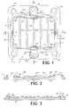
- Figure 1 shows an illustrative filter plate according to the present invention, in plan view.
- Figure 2 shows a sectional elevation view of the Figure 1 plate, taken along line A-A thereof, and
- Figure 3 is a sectional elevation view of the Figure 1 plate, taken along line B-B thereof.
- the plate member 10 is generally planar and may be rectangular in shape, having a generally square shape in the specific embodiment shown in Figure 1.
- the plate has a substantially flat bottom surface 12 (see Figures 2 and 3), and a top surface 14 which is substantially flat in the peripheral portions of the plate.
- the top surface 14 has an upwardly extending wall 16 circumscribingly bounding a flow channel 18 of generally rectangular shape within the bounding wall.
- a liquid inlet port 20 is provided at a medial part of a first side 22 of the flow channel.
- a liquid outlet port 24 is correspondingly provided at a medial part of a second side 26 of the flow channel opposite the first side thereof.
- the liquid inlet port 20 is joined in liquid flow communication with a liquid feed through 28 extending transversely across the first side of the flow channel.
- the liquid outlet port 24 is joined in liquid flow communication with a liquid collection trough 30 extending transversely across the second side of the flow channel.
- a plurality of spaced apart partitions 32a, 32b, 32c, 32d, and 32e extend upwardly from the floor 34 of the flow channel between the liquid feed through 28 and the liquid collection trough 30.
- the partitions 32a-32e are of lesser height than the wall 16 circumscribing the flow channel and are substantially parallel to each other, to define a series of sub-channels extending longitudinally between the liquid feed trough and the liquid collection trough.
- the liquid feed trough 28 is of progressively decreasing depth from its medial portion, in communication with the liquid inlet port, to its marginal extremities 36 and 36a.
- the liquid collection trough 30 is of progressively decreasing depth from its medial portion in communication with the liquid outlet port, to its marginal extremities 38 and 40.
- depth refers to the maximum vertical dimension of the feed or collection trough as measured from the bottom of the trough to the plane of the floor 34 of the flow channel 18.
- the plate may feature, as shown in Figure 1, an interior circumscribing wall 42 of lesser height than the circumscribing main wall 16, to provide a bearing structure for retention of the foraminous support shown in Figures 4-5 and described more fully hereinafter.
- the outer circumscribing wall 16 may as shown be formed with integral cylindrical flanges 44, 46, 48, and 50, each of which circumscribes a circular opening in the periphery of the plate to accommodate the positioning of the plate on spaced-apart rods, as hereinafter shown with reference to Figure 6 hereof.
- respective oblong openings 51 and 52 to accommodate the liquid feed and liquid withdrawal conduits which are employed to introduce liquid to and remove liquid from the flow channels defined by adjacently paired stacked plates.
- Such feed and discharge liquid conduits are more fully shown and described with reference to Figure 6 herein.
- the respective liquid feed and discharge conduits are suitably formed with spaced-apart perforations therein which permit egress or ingress of liquid into or out of the flow channel via the above-described respective liquid inlet and outlet ports of the plate.
- the liquid inlet and outlet ports of the plate are suitably provided with gasket elements 56 and 58 as shown in Figure 1, at the bottom surface 12 of the plate.
- a filter plate suitable for filtration of aqueous biomass suspensions may be generally of square shape as shown in Figure 1 with sides on the order of about 6 inches, and with feed and collection troughs 28 and 30 which are each 2 millimeters deep at their medial portions, continuously decreasing to a depth of 1.5 millimeters at their respective extremities (peripheral portions 36 and 36a of feed trough 28, and peripheral portions 38 and 40 of collection trough 30).
- the transverse dimension (width) of each of the sub-channels defined by the partition walls 32a-e is approximately 2 centimeters.
- the filter plate may be provided with a circumbscribing main wall 16 and an interior circumscribing wall 42 of lesser height than the main wall. Between these respective walls is formed a circumscribing channel (see Figures 2 and 3), into which suitable openings 5 and 6 may communicate as shown in Figures 1 and 3. These respective openings are usefully employed as filtrate (permeate) flow channels to convey or drain the solids-depleted filtered liquid or other permeate from the stacked plate assembly.
- Openings 5 and 6 may also be usefully employed as gas flow openings to assist in draining the stacked plate filter upon cessation of normal operation for regeneration.
- gas from a suitable supply source (not shown) may be introduced in openings 5 and/or 6 to pressurize the flow channel 18 to a sufficient extent where the same can be drained of accumulated biomass suspension upon the termination of normal liquid flows through the system.
- these respective openings could be employed for introduction and egress of steam for steam sterilization of the system or for flowing a chemical sterilant through the flow channel 18 prior to initiation or re-initiation of normal filtration operation.
- openings 5 and 6 are disposed in the channel between bounding walls 42 and 16, as shown in Figure 7, described more fully hereinafter, it is also possible to utilize openings 5 and 6 as respective secondary fluid inlet and discharge passages, for flowing a secondary fluid through the foraminous support for mass transfer contacting of the liquid introduced into the flow channel 18 from inlet port 20 and discharged from the flow channel in outlet port 24.
- openings 5 and 6 it may be advantageous to symmetrically "block" the channel between bounding walls 41 and 16, at symmetrically opposed regions, as shown in Figure 1, where channel blocking segment 8 is disposed in the channel along the side thereof containing opening 5, and channel blocking segment 9 is similarly disposed in the channel proximate to opening 6.
- fluid entering in opening 5 is diverted downwardly in the channel as shown in the drawing and across the lower portion of the channel as shown until it encounters the channel blocking element 9. Subsequently, when the fluid so introduced is issued from the edges of the foraminous support into the opposite portion of the channel as shown, it flows to outlet opeing 6.
- Openings 5 and 6 may be appropriately sealed between adjacent plates by provision of suitable gasket means 3 and 5, respectively, at the flat bottom surface 12 of the plate, as shown in dotted line representation in Figure 1.
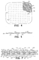
- FIGS. 4 and 5 show respective top plan and edge views of an illustrative foraminous support element for the stacked plate filter assembly. Corresponding features of the plate are shown by the same reference numerals in these two drawings.
- the foraminous support 80 is simply a support element of generally rectangular shape which is supportively reposable at a first face 82 thereof on the partitions 32a-32e and the circumscribing wall 42 of the plate element, with a first filter sheet, e.g. a filter paper sheet, therebetween.
- a first filter sheet e.g. a filter paper sheet
- the foraminous support 80 is likewise supportively reposable at a second face 84 thereof on the partitions and inner bounding wall of a complementary filter plate paired with the filter plate against which the first face 82 of the support is reposed.
- the second face of the foraminous support likewise has a sheet filter element between its surface and the partitions of the adjacent plate member.
- the foraminous support is formed with a plurality of longitudinally extending interior liquid flow channels 86 and a plurality of transversely extending interior liquid flow channels 88, wherein the longitudinal and transverse channels criss-cross one another to establish an extended interconnected network for liquid flow through the interior of the support element.
- the liquid (permeate) component of the solids-liquid suspension passes through the filter paper and openings 90 into the interior liquid flow network comprising channels 86 and 88, for flow through the foraminous support to the edge regions thereof, where the solids-depleted liquid filtrate issues from the support into the channel between bounding wall 16 and 42 and may be removed via openings 5 and 6.
- Figure 7 is a transverse sectional elevation view of a stacked plate filter assembly according to the invention, showing the arrangement of the constituent parts thereof, and numbered correspondingly to Figures 1-5 herein.
- the identical complementary upper and lower plates are mated to one another.
- suitable gaskets (not shown) may be interposed (e.g., in opposing grooves) between the abutting top surfaces of the respective opposed bounding walls 16.
- a lower filter sheet 100 is disposed between the lower surface 82 of the foraminous support, and the partition bearing surface of the lower filter plate.
- an upper filter sheet 102 is interposed between the top surface 84 of the foraminous support and the partition bearing surfaces of the upper filter plate.
- the foraminous support has been shown as a structural element of mat-like form, the function of the support is merely to positionally retain the filter sheet on either side thereof and to accommodate the interior flow of solids-depleted liquid toward the filtrate (permeate) collection means associated with the filter plate.
- the foraminous support may comprise a sintered ceramic material, e.g., of alumina, zirconia, etc., having an internal network of interconnected voids with an average void passage diameter on the order of about 1 micron.
- Such support may have a total void space on the order of from about 50 to about 90% by volume, e.g., about 80% voids.
- such sintered ceramic plate may be glazed or otherwise treated on selected portions of its surface to render same liquid impermeable in such regions.
- the sintered ceramic plate could be selectively glazed to provide for flow through the interior thereof of a second fluid, e.g., a dialysis fluid for desalting of proteins, amino acids, and/or other biological substances being contacted with the filter sheets supported on such sintered plate.
- Figure 6 shows an exploded, perspective view of a stacked plate filter according to the present invention, as disposed on a base comprising a mounting plate 200 having vertically upwardly extending rods 202, 204, 206, and 208 at its respective corner portions, as shown.
- a filter plate 210 Mounted on the base as a lowermost element of the stack, is a filter plate 210 of the type shown in Figures 1-3.
- the respective rods 202, 206, and 208 extend through the circular openings in the plate which are surrounded by the respective cylindrical flanges 212, 216, and 218 (a similar flanged opening, not visible in this view, is provided for rod 204).
- the liquid feed conduit 221 for the filter extends through an opening in the base plate 200 and through the liquid inlet opening 251 of the plate member, so that when filter plate 210 is in position, the liquid feed opening 253 is in register with the liquid inlet opening 251 and liquid inlet port 220 of the filter plate.
- liquid withdrawal conduit 223 extends through a corresponding opening in the base plate 200 and liquid outlet opening 252, whereby the liquid discharge opening 257 in conduit 223 is brought into register with liquid outlet port 224 when the bottom filter plate 210 is properly positioned.
- the filter sheet 300 Reposed on the upper bearing surfaces of the partition walls 232 of the bottom filter plate is a filter sheet 300.
- the filter sheet may be a paper filter sheet, comprising a non-woven web of cellulosic fibers, or any other replaceable or disposable filtration medium commonly provided in sheet form and which is readily cut or otherwise shaped to the form required in the filter of the present invention.
- a particularly advantageous filter sheet in filter systems of the type envisioned by the present invention are polysulfone filter sheets which are readily commercially available.
- the foraminous support 302 Overlying the filter sheet 300 is the foraminous support 302, which is of the form illustratively shown and described with reference to Figures 4-5 herein. Overlying the foraminous support 302 is filter sheet 306, which may be identical in shape and construction to filter sheet 300.
- a filter plate 310 Overlying the upper filter sheet 306 is a filter plate 310 according to the present invention, of identical construction to lower plate 210 but positionally inverted with respect to the lower plate, to form interior sub-channels for liquid flow which are configured as shown in Figure 7 when the stacked filter plate assembly of Figure 6 is fully mated with respect to its constituent elements.
- the upper filter plate 310 is configured with openings 364 and 360 communicating with the circumscribing channel (see Figures 2 and 3, showing the channel as disposed between bounding walls 42 and 16) surrounding the main flow channel on the plate. Opening 364 in this configuration is closed by a suitable plug, while opening 360 has a fluid introduction passage 362 in flow communication therewith, for feeding of a second liquid, e.g., dialysate solution, into the circumscribing channel (the direction of liquid feeding being indicated by the arrow P).
- a second liquid e.g., dialysate solution
- the liquid enters the foraminous support through the edge openings 386 thereof and flows therethrough to the opposite side of the lower filter plate and into the circumscribing channel of the lower plate for discharge through openings 368 and 369 and out of the system through the fluid discharge passage 369 in the direction indicated by arrow Q.
- Circumscribing channel opening 366 of the lower filter plate is closed by a suitable plug in this arrangement.
- the stacked filter plate assembly may be retained on the rods 202, 204, 206, and 208 by suitable mechanical fasteners, such as washers 312, 314, 316, and 318, and respective lock-nuts 320, 322, 324, and 326.
- suitable mechanical fasteners such as washers 312, 314, 316, and 318, and respective lock-nuts 320, 322, 324, and 326.
- the rods 202, 204, 206, and 208 are suitably configured with threaded outer surfaces.
- respective sections of stacked plates may be variously joined in fluid flow communication with one another in series to form stacked filter "trains" whose constituent sections may be employed to carry out a number of unit operations on an influent or feed material, such as concentrating (dewatering), washing, dialyzing, desalting, etc.
- a stacked filter train of series-connected sections may be employed in a cell culturing system of the type disclosed and claimed in my copending patent application U.S. Serial No. 06/936,486 filed November 26, 1986, the disclosure of which is hereby incorporated by reference, in applications such as the production in vitro of human immunodeficiency virus (HIV) on cellular or synthetic microbead substrates.
- HIV human immunodeficiency virus
- a first stacked plate section could be employed to concentrate HIV
- a second section could be utilized to add media to the system
- a third section could be used to withdraw media from the system, all without withdrawing any virus, such as might otherwise present a risk of immunosuppressive infection.
- a closed system virus culturing arrangement is provided, which is highly advantageous not only for the production of HIV but also the culturing or other processing of pathogenic bacterial, viral, and yeast species.
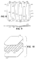
- FIG 8 is a plan view of a support for a unitary filter element.
- the support 400 includes a circumscribing frame 402 formed by the respective side portions 410, 411, 412, and 413.
- the circumscribing frame is associated with an array of spaced-apart and substantially parallelly aligned ribs 414, 415, 416, 417 and 418 extending between and joined at their opposite ends to the frame (sides 412 and 413, respectively).
- the ribs and frame thus corporately form a series of corresponding substantially parallel filtrate flow channels 420, 422, 424, 426, 428 and 430, as shown.
- Openings 407 are provided in the frame in liquid flow communication with the filtrate flow channels for egress of filtrate from the filtrate flow channels through the frame openings.
- Figure 9 is an edge elevational view of the filter element comprising the support shown in Figure 8.
- Figure 10 is an exploded perspective view of the unitary filter element whose edge elevational view is shown in Figure 9.
- the unitary filter element features a first filter sheet 406 which is continuously secured along its margins to a first face of the frame 402.
- a second filter sheet 400 is continuously secured along its margins to a second face of the frame.
- the first and second filter sheets together with the frame define an enclosed interior volume comprising the filtrate flow channels separated by the ribs. Accordingly, filtrate entering the enclosed liquid volume through the first and second filter sheets, i.e., by permeation of liquid through the filter sheets, may flow in the filtrate flow channels and be discharged form the filter elements through the frame openings 407 which are in liquid communication with the filtrate flow channels.
- the above-described unitary filter element may suitably be constructed and employed for short term filtration operation, e.g., on the order of about 6 months, following which the filter element may be discarded and replaced with a corresponding new element.
- the unitary filter element may be formed of any suitable materials, such as for example polysulfone, polyvinylidene fluoride, polypropylene, nitrocellulose, polyethylene, and the like, as may be useful in the desired end use filtration application.
- the first and second filter sheets may be continuously secured along their margins to the respective first and second faces of the frame by any suitable joining or attachment method, including, but not limited to, ultrasonic welding, heat sealing, solvent welding, and adhesive bonding, as well as mechanical affixation.
- any number of paired filter plates, with interposed support element and filter sheets, may be assembled to form a cross-flow filter.
- the number of stacked filter plates in a specific filter system will be largely determined by space requirements and constraints, allowable pressure drop in the system, solids concentration and volumetric flow rate of the liquid to be filtered, and the filtration efficiency of the specific filter sheets employed.
- a superficial velocity of aqueous biomass suspension in the range of 1.5 meters per second through the flow channel defined between adjacent paired plates is readily accommodated, at a volumetric feed rate of approximately 1 liter of aqueous biomass suspension per minute in the flow channel, without any significant maldistribution of the liquid flow therein.
- the influent liquid is distributed by the liquid feed trough so that substantially equal amounts of liquid are passed into each of the transversely spaced-apart sub-channels between adjacent plates.
- the pressure through the collection trough is equalized to the extent that the volumetric feedrate of liquid to be filtered is substantially equal in each of the sub-channels.
- the filter assembly comprising filter plates of the present invention is highly hydraulically uniform in operation, without the existence or operational tendencies toward flow anomalies, such as bypassing, channeling, and "dead space" formations, which are found in stacked plate filters of the prior art. Accordingly, the stacked plate filter assembly of the present invention achieves a substantial advance in the art, which permits the full areal extent of the filter sheet media to be efficiently employed for solids-liquid separation. In consequence, filter assemblies according to the invention are capable of extended operation relative to the on-stream operating periods characteristic of prior art filters, before regeneration or drainage and replacement of filter elements is necessary.
Landscapes
- Chemical & Material Sciences (AREA)
- Chemical Kinetics & Catalysis (AREA)
- Filtration Of Liquid (AREA)
- Apparatus Associated With Microorganisms And Enzymes (AREA)
Applications Claiming Priority (4)
| Application Number | Priority Date | Filing Date | Title |
|---|---|---|---|
| US104177 | 1987-10-02 | ||
| US07/104,177 US4867876A (en) | 1987-10-02 | 1987-10-02 | Filter plate, filter plate element, and filter comprising same |
| US07/364,616 US5049268A (en) | 1987-10-02 | 1989-06-09 | Filter plate, filter plate element, and filter comprising same |
| US07/760,339 US5232589A (en) | 1987-10-02 | 1991-09-16 | Filter element and support |
Publications (2)
| Publication Number | Publication Date |
|---|---|
| EP0310385A2 true EP0310385A2 (de) | 1989-04-05 |
| EP0310385A3 EP0310385A3 (de) | 1989-12-13 |
Family
ID=27379674
Family Applications (1)
| Application Number | Title | Priority Date | Filing Date |
|---|---|---|---|
| EP8888309035A Withdrawn EP0310385A3 (de) | 1987-10-02 | 1988-09-29 | Filterplatte, Filterplattenelement und diese enthaltendes Filter |
Country Status (1)
| Country | Link |
|---|---|
| EP (1) | EP0310385A3 (de) |
Cited By (4)
| Publication number | Priority date | Publication date | Assignee | Title |
|---|---|---|---|---|
| EP0478623A4 (en) * | 1989-06-09 | 1992-12-09 | Henry B. Kopf | Filter plate, filter plate element, and filter comprising same |
| US7527062B2 (en) | 2001-02-15 | 2009-05-05 | Steelkor, L.L.C. | Kitchenware washers and methods of manufacturing the same |
| US7763119B2 (en) | 2005-04-22 | 2010-07-27 | Steelkor, L.L.C. | Kitchenware washers and methods of manufacturing the same |
| CN116212483A (zh) * | 2021-12-06 | 2023-06-06 | 中国石油天然气股份有限公司 | 一种弹性过滤结构及泵下滤砂装置 |
Families Citing this family (1)
| Publication number | Priority date | Publication date | Assignee | Title |
|---|---|---|---|---|
| US9265400B2 (en) | 2005-04-22 | 2016-02-23 | Duke Manufacturing Co. | Commercial kitchenware washers and related methods |
Family Cites Families (4)
| Publication number | Priority date | Publication date | Assignee | Title |
|---|---|---|---|---|
| IT7868888A0 (it) * | 1978-08-10 | 1978-08-10 | Fiat Eng | Apparecchiatura per osmosi inversa |
| WO1981002681A1 (en) * | 1980-03-19 | 1981-10-01 | Gambro Ag | A device for the diffusion of substances between two fluids via semipermeable membranes |
| WO1986000237A1 (en) * | 1984-06-18 | 1986-01-16 | Permutit - Boby Limited | Fluid separation cells and spacers for use in these |
| DD229603A1 (de) * | 1984-12-14 | 1985-11-13 | Medizin Labortechnik Veb K | Membranfilterplatte |
-
1988
- 1988-09-29 EP EP8888309035A patent/EP0310385A3/de not_active Withdrawn
Cited By (5)
| Publication number | Priority date | Publication date | Assignee | Title |
|---|---|---|---|---|
| EP0478623A4 (en) * | 1989-06-09 | 1992-12-09 | Henry B. Kopf | Filter plate, filter plate element, and filter comprising same |
| US7527062B2 (en) | 2001-02-15 | 2009-05-05 | Steelkor, L.L.C. | Kitchenware washers and methods of manufacturing the same |
| US7763119B2 (en) | 2005-04-22 | 2010-07-27 | Steelkor, L.L.C. | Kitchenware washers and methods of manufacturing the same |
| CN116212483A (zh) * | 2021-12-06 | 2023-06-06 | 中国石油天然气股份有限公司 | 一种弹性过滤结构及泵下滤砂装置 |
| CN116212483B (zh) * | 2021-12-06 | 2024-06-07 | 中国石油天然气股份有限公司 | 一种弹性过滤结构及泵下滤砂装置 |
Also Published As
| Publication number | Publication date |
|---|---|
| EP0310385A3 (de) | 1989-12-13 |
Similar Documents
| Publication | Publication Date | Title |
|---|---|---|
| US4956085A (en) | Filter plate, filter plate element and filter comprising same | |
| US4867876A (en) | Filter plate, filter plate element, and filter comprising same | |
| US4882050A (en) | Filter plate, filter plate element, and filter comprising same | |
| EP0478623B1 (de) | Filterplatte, filterplattenelement und filter, der dieselben enthält | |
| US5342517A (en) | Filtration cassette article, and filter comprising same | |
| EP0980285B1 (de) | Filter mit darin enthaltener filtrationskassette | |
| EP0814896B1 (de) | Filter mit darin enthaltener filtrationskassette | |
| US5232589A (en) | Filter element and support | |
| US4801381A (en) | Ultrafiltration apparatus | |
| JP2885826B2 (ja) | 微細分散された成分を含む液体を直交作業でろ過する際にフィルタ被覆層の形成を防止するかまたはフィルタ被覆層を分解する方法および装置 | |
| EP0588902A4 (de) | Drehfilter und filterelement dafür. | |
| JP2016030257A (ja) | デッドエンド濾過用およびクロスフロー濾過用のフィルタモジュール | |
| US20230302410A1 (en) | Filter cassette article, and filter comprising same | |
| WO2019108082A1 (en) | Filtration assembly and filtration system including the same | |
| EP0310385A2 (de) | Filterplatte, Filterplattenelement und diese enthaltendes Filter | |
| US5160433A (en) | Laboratory scale ultrafiltration apparatus | |
| US20040045890A1 (en) | Hollow fiber membrane cassette | |
| AU2002236864B2 (en) | Hollow fiber membrane cassette | |
| AU2002236864A1 (en) | Hollow fiber membrane cassette | |
| GB2130111A (en) | Filtration apparatus | |
| SU1291173A1 (ru) | Ультрафильтр | |
| RU2033188C1 (ru) | Многокамерный мембранный фильтр | |
| RU2040317C1 (ru) | Мембранный фильтр | |
| RU2073555C1 (ru) | Фильтрационный аппарат |
Legal Events
| Date | Code | Title | Description |
|---|---|---|---|
| PUAI | Public reference made under article 153(3) epc to a published international application that has entered the european phase |
Free format text: ORIGINAL CODE: 0009012 |
|
| AK | Designated contracting states |
Kind code of ref document: A2 Designated state(s): AT BE CH DE ES FR GB GR IT LI LU NL SE |
|
| PUAL | Search report despatched |
Free format text: ORIGINAL CODE: 0009013 |
|
| AK | Designated contracting states |
Kind code of ref document: A3 Designated state(s): AT BE CH DE ES FR GB GR IT LI LU NL SE |
|
| 17P | Request for examination filed |
Effective date: 19900606 |
|
| 17Q | First examination report despatched |
Effective date: 19910807 |
|
| STAA | Information on the status of an ep patent application or granted ep patent |
Free format text: STATUS: THE APPLICATION IS DEEMED TO BE WITHDRAWN |
|
| 18D | Application deemed to be withdrawn |
Effective date: 19930305 |