EP0310425A1 - Drucker mit einer Papiereinzugsvorrichtung - Google Patents
Drucker mit einer Papiereinzugsvorrichtung Download PDFInfo
- Publication number
- EP0310425A1 EP0310425A1 EP88309113A EP88309113A EP0310425A1 EP 0310425 A1 EP0310425 A1 EP 0310425A1 EP 88309113 A EP88309113 A EP 88309113A EP 88309113 A EP88309113 A EP 88309113A EP 0310425 A1 EP0310425 A1 EP 0310425A1
- Authority
- EP
- European Patent Office
- Prior art keywords
- advancing
- medium
- recording medium
- path
- sheet
- Prior art date
- Legal status (The legal status is an assumption and is not a legal conclusion. Google has not performed a legal analysis and makes no representation as to the accuracy of the status listed.)
- Withdrawn
Links
- 230000007246 mechanism Effects 0.000 claims abstract description 57
- 238000003780 insertion Methods 0.000 claims abstract description 17
- 230000037431 insertion Effects 0.000 claims abstract description 17
- 230000003213 activating effect Effects 0.000 claims abstract description 8
- 230000004044 response Effects 0.000 claims abstract description 5
- 230000004913 activation Effects 0.000 claims abstract description 4
- 238000011144 upstream manufacturing Methods 0.000 claims description 8
- 230000009471 action Effects 0.000 description 1
- 230000005540 biological transmission Effects 0.000 description 1
- 230000009849 deactivation Effects 0.000 description 1
- 238000010586 diagram Methods 0.000 description 1
- 238000004519 manufacturing process Methods 0.000 description 1
- 230000004048 modification Effects 0.000 description 1
- 238000012986 modification Methods 0.000 description 1
- 230000001360 synchronised effect Effects 0.000 description 1
- 229920003002 synthetic resin Polymers 0.000 description 1
- 239000000057 synthetic resin Substances 0.000 description 1
Images


Classifications
-
- B—PERFORMING OPERATIONS; TRANSPORTING
- B41—PRINTING; LINING MACHINES; TYPEWRITERS; STAMPS
- B41J—TYPEWRITERS; SELECTIVE PRINTING MECHANISMS, i.e. MECHANISMS PRINTING OTHERWISE THAN FROM A FORME; CORRECTION OF TYPOGRAPHICAL ERRORS
- B41J13/00—Devices or arrangements of selective printing mechanisms, e.g. ink-jet printers or thermal printers, specially adapted for supporting or handling copy material in short lengths, e.g. sheets
- B41J13/0054—Handling sheets of differing lengths
-
- B—PERFORMING OPERATIONS; TRANSPORTING
- B41—PRINTING; LINING MACHINES; TYPEWRITERS; STAMPS
- B41J—TYPEWRITERS; SELECTIVE PRINTING MECHANISMS, i.e. MECHANISMS PRINTING OTHERWISE THAN FROM A FORME; CORRECTION OF TYPOGRAPHICAL ERRORS
- B41J11/00—Devices or arrangements of selective printing mechanisms, e.g. ink-jet printers or thermal printers, for supporting or handling copy material in sheet or web form
- B41J11/0095—Detecting means for copy material, e.g. for detecting or sensing presence of copy material or its leading or trailing end
Definitions
- the present invention relates generally to a printer equipped with a paper loading device, and more particularly to a printing apparatus which can be automatically loaded with a cut sheet fed by a sheet feeding mechanism, and manually loaded with a recording medium inserted by an operator.
- a printer equipped with a paper loading device which permits the printer to be automatically loaded with cut sheets that are fed one after another from a stacker of a sheet feeding device, and manually loaded with a desired recording medium that is inserted into the printer by an operator.
- the paper loading device of this type of printer generally has a sheet feeding path along which the cut sheets are fed, and a separate paper insertion path along which the desired recording medium is manually inserted.
- the cut sheets are stored in a stack on a suitable stacker provided in the loading device.
- the cut sheets are fed one after another along the sheet feeding path by a sheet feeding mechanism, into a medium advancing path defined in the printer.
- the printer is loaded with the recording medium different from the cut sheets, the medium is manually inserted into the paper insertion path and is then automatically advanced along the medium advancing path in the printer.
- the printer of the type indicated above has suitable selector or switching means for selectively loading the printer with either an automatically fed cut sheet or a manually inserted recording medium.
- the switching means is provided to prevent the sheet feeding mechanism from feeding the cut sheet while another recording medium is present in the manual insertion path, thereby preventing the printing mechanism of the printer from being simultaneously loaded with the two different recording media.
- the switching means may be a mechanism or a switch which is adapted to inhibit the activation of the sheet feeding mechanism when the printer is placed in a manual paper insertion mode. If the sheet feeding mechanism is connected to a drive source which is provided in the printer to advance the recording medium to the printing mechanism, the switching means is adapted to disconnect the sheet feeding mechanism from the power source in the printer, when the manual paper insertion mode is selected. If the sheet feeding mechanism is driven by a separate exclusive drive source provided in the paper feeding device, the switching means is adapted to inhibit the operation of that exclusive drive source.
- the provision of the switching means undesirably increases the number of components of the printer, and consequently pushes up the cost of manufacture of the printer as a whole.
- the present invention was developed to solve the problem described above. It is accordingly an object of the present invention to provide a printing apparatus equipped with a paper feeding device, which is capable of automatically and manually loading the printer in a correct manner, without the provision of a switching means or mechanism as provided in the conventional printing apparatus.
- a printing apparatus comprising: a medium advancing mechanism for advancing a recording medium along an advancing path; a printing mechanism for printing on the recording medium; a sheet feeding mechanism for feeding sheets of paper one after another from a stack of the sheets to the advancing path; a paper insertion path along which a manually inserted medium is guided to the advancing path; sensing means for detecting the recording medium existing in the advancing path; and control means for activating the medium advancing mechanism in response to a command to load the printing mechanism with the recording medium.
- the control means is adapted to determine whether the sensing means has detected the manually inserted medium within a predetermined time after the activation of the medium advancing mechanism, or not.
- the control means activates the sheet feeding mechansim if the control means determines that the sensing means has not detected the manually inserted medium within the predetermined time.
- the control means operates the medium advancing mechanism for the predetermined time, in response to a medium loading command. If the manually inserted recording medium is detected by the sensing means within this time period, this indicates that the manually inserted medium is advanced to the printing mechanism. In this case, therefore, the sheet feeding mechanism is not activated. If the manually inserted medium is not detected within the predetermined time period, this indicates that the paper insertion path is not loaded with a manually inserted recording medium. In this case, therefore, the sheet feeding mechanism is activated to automatically feed a cut sheet from the sheet stack to the printing mechanism of the printer.
- either the cut sheets of the sheet stack or another type of recording medium can be suitably supplied to the printing mechanism, without the provision of a conventionally used switching mechanism.
- the instant printing apparatus is practically advantageous over the conventional arrangement described above.
- the medium advancing mechanism includes an advancing roll rotatable about an axis thereof and having a circumferential surface partially defining the advancing path, an advancing motor for rotating the advancing roll, and a downstream and an upstream pinch roll which are disposed adjacent to the circumferential surface of the advancing roll so as to press the recording medium against the circumferential surface of the advancing roll.
- the downstream and upstream pinch rolls are spaced apart from each other in a circumferential direction of the advancing roll along the advancing path.
- the sensing means is disposed between the downstream and upstream pinch rolls.
- control means includes a computer which operates to execute a step of determining whether the predetermined time has passed before the sensing means has detected the manually inserted medium, or not, and a step of activating the sheet feeding mechanism if the predetermined time has passed before the sensing means has detected the manually inserted medium.
- the computer may be adapted to further execute a step of determining whether the predetermined time has passed after the deactivation of the sheet feeding mechanism, before the sensing means has detected the cut sheet, and a step of activating alarm means for informing a user of the printing apparatus of a trouble, if the predetermined time has passed before the sensing means has detected the cut sheet.
- a planar platen 2 is disposed within a printer housing 1.
- a medium advancing roll 3 which is supported by the frame 1 such that the advancing roll 3 is bidirectionally rotatable.
- the advancing roll 3 is adapted to advance a recording medium P in the form of a cut sheet P1 or a manually inserted cut sheet P2, to the platen 2.
- a paper guide 5 is disposed along a lower part of the circumferential surface of the advancing roll 3, so as to define therebetween a paper advancing path 4 leading to the platen 2.
- a thermal print head 8 for printing on the recording medium P on the platen 2, via a thermal print ribbon (not shown).
- the thermal print head 8 is reciprocated along the platen 2.
- a feed roll 9 and a pinch roll 10 which are rotatably supported so as to further advance the recording medium P from the platen 2.
- the feed roll 9 is connected to the advancing roll 3 for synchronized rotation with the advancing roll 3.
- the pinch roll 10 is movable by a suitable drive mechanism (not shown), toward and away from the feed roll 9, so that the pinch roll 10 is pressed against the feed roll 10 only when the recording medium P is advanced from the platen 2 toward an ejection roll 31 (which will be described).
- a first sheet sensor 11 is secured to the paper guide 5, for detecting the recording medium P while it is advanced along the advancing path 4.
- the sheet sensor 11 produces an electric signal indicative of the presence or absence of the recording medium P.
- the advancing roll 3, pinch rolls 6a, 6b, feed and pinch rolls 9, 10 and paper advancing motor 7 constitute a medium advancing mechanism F for advancing the recording medium P along the advancing path 4.
- the platen 2 and thermal print head 8 constitute a printing mechanism M for printing on the recording medium P.
- the paper loading device S is adapted to automatically feed the cut sheets P1 or manually insert the cut sheet P2.
- the loading device S has a frame 15 which is substantially L-shaped in cross section as viewed in Fig. 1 and is secured to a rear upper corner of the printer housing 1.
- the frame 15 has a support plate 16 mounted in its almost middle portion, so as to extend obliquely in a rear upward direction, for supporting a stack of the cut sheets P1.
- Above the lower or inner end portion of the support plate 16 there is rotatably supported a feed roll 17 for feeding the cut sheets P1 from the support plate 16.
- the feed roll 17 has a large-diameter portion 17a, and a small-diameter portion 17b.
- the support plate 16 is formed with a pair of sheet separator pieces 18 provided at its lower end corners, for separating the uppermost cut sheet P1 from the remainder of the stack P1 when the uppermost cut sheet P1 is fed by the feed roll 17.
- the support plate 16 has a recess 19 formed at its lower end portion.
- a presser member 20 is movably accommodated in the recess 19, and is biased by a suitable spring for urging the lower end portion of the sheet stack P1 against the sheet separator pieces 18.
- the large-diameter portion 17a comes into frictional engagement with the surface of the uppermost cut sheet P1 on the support plate 16, thereby applying a forward feeding force to the uppermost cut sheet P1, whereby the uppermost cut sheet P1 is separated from the second cut sheet P1 by the sheet separator pieces 18 and is fed toward the advancing roll 3. More specifically, one rotation of the feed roll 17 causes the cut sheet P1 to be fed until the leading edge of the sheet P1 reaches a pressure nip 40 between the advancing roll 3 and the downstream pinch rolls 6a.
- the support plate 16, feed roll 17 and SHEET FEEDING motor 21 constitute a sheet feeding mechanism T for feeding the cut sheets P1 to the nip 40 of the rolls 3, 6a.
- a low-friction disc 34 is rotatably supported in coaxial relation with the feed roll 17.
- the disc 34 is adapted to engage the trailing edge of the cut sheet P1 and thereby prevent the cut sheet P1 from engaging the feed roll 17, when the sheet P1 is moved in the reverse direction toward the sheet feeding mechanism T.
- the printer housing 1 has a first aperture 22 formed in its rear wall, while the frame 15 of the paper loading device S has a second aperture 23 formed in its front wall, such that the first and second apertures 22, 23 are substantially aligned with each other.
- the cut sheet P1 fed from the support plate 16 is fed along a sheet feeding path 24 leading to the second aperture 23.
- a paper insertion path 25 which extends from the first and second apertures 22, 23 and which is open upward at its upper end.
- the paper insertion path 25 merges at its lower end with the sheet feeding path 24.
- An elastic sheet member 26 formed of a synthetic resin is attached at its upper end to the front wall of the frame 15 through which the second aperture 23 is formed. The sheet member 26 normally closes the second aperture 23, but is elastically yieldable to permit the cut sheet P1 to be fed toward the nip 40 of the advancing and pinch rolls 3, 6a.
- the elastic sheet member 26 elastically yields toward the first aperture 22 of the printer housing 1, whereby the lower end of the second aperture 23 is opened leading to the first aperture 22.
- the cut sheet P1 is permitted to pass through the second and first apertures 23, 22 toward the nip 40 of the rolls 3, 6a.
- the recording medium P (P1 or P2) is moved in the reverse direction toward the paper loading device S, the trailing end of the medium P abuts on the elastic sheet member 26, and the medium P is guided into the paper insertion path 25.
- the above-indicated paper insertion path 25 is used for manually loading the printer with the desired recording medium in the form of the cut sheet P2 different from the cut sheets P1. Described more specifically, the cut sheet P2 is inserted into the paper insertion path 25 through its upper open end 25a, until the leading edge of the cut sheet P2 reaches the nip 40 of the advancing and pinch rolls 3, 6a. The cut sheet P2 inserted in the path 25 is advanced toward the printing mechanism M when the advancing roll 3 is rotated in the forward direction.
- a two-arm sensing member 27 which is pivotally supported at its intermediate portion.
- a second sheet sensor 28 consisting of a photoelectric switch is provided adjacent to one end of the sensing member 27. Normally, the other end of the sensing member 27 is placed in its upper position so as to lie on the sheet feed path 24, as indicated in solid line in Fig. 1. In this condition, the signal produced by the second sheet sensor 28 indicates the absence of the cut sheet P1 in the feeding path 24.
- the sensing member 27 is pivoted to its operated position as indicated in broken line in Fig. 1. In this condition, the signal produced by the sensor 28 indicates the presence of the cut sheet P1 in the sheet feeding path 24.
- the frame 15 has a tray 30 pivotally supported at a portion thereof above the rear portion of the upper wall of the printer housing 1.
- the tray 30 is pivoted at its one end between an operated position indicated in solid line in Fig. 1, and a non-operated position indicated in broken line in the same figure.
- the cut sheets P which have been ejected through a paper outlet 29 above the printing mechanism M are received on the tray 30 placed in the operated position.
- the ejection roll 31 Adjacent to the pivotally connected end of the tray 30, there is disposed the ejection roll 31 rotatably supported by the frame 15, for engaging the recording medium P which has been fed through the paper outlet 29.
- the frame 15 also has a guide 32 pivotally supported adjacent to the ejection roll 31.
- the guide 32 is biased by a spring 33 toward its advanced position shown in Fig. 1, in which the guide 32 is held in abutment on a part of the frame 15.
- the recording medium P is ejected through the paper outlet 29
- the recording medium P is guided along a guide surface 32a of the guide 32 while being curved along the guide surface 32a, whereby the medium P is ejected onto the tray 30.
- the medium P is a medium difficult to be curved, such as a postcard
- the medium P is guided onto the tray 30 while the guide 32 is pivoted toward its retracted position against a biasing action of the spring 33.
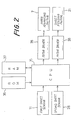
- the instant printer is controlled by a control system as shown in Fig. 2.
- the control system includes control means in the form of a central processing unit (CPU) 35, a read-only memory (ROM) 36, and a random-access memory (RAM) 37.
- the ROM 36 stores a control program as illustrated in the flow chart of Fig. 3, for controlling the operation of the printer.
- the CPU 35 receives the signals produced by the first and second sheet sensors 11, 28 described above, and applies drive signals to the PAPER ADVANCING motor 7 and the SHEET FEEDING motor 21 via motor drivers 38, in response to the signals from the sensors 11, 28 and according to the control program stored in the ROM 36.
- the CPU 35 executes a control routine of the flow chart of Fig. 3. Initially, the control flow goes to step S1 to turn on the PAPER ADVANCING motor 7, and thereby rotate the advancing roll 3 in the forward direction. Then, the control flow goes to step S2 to determine whether the first sheet sensor 11 has produced a signal indicative of the presence of the medium P in the advancing path 4, or not, that is, whether the first sheet sensor 11 has detected the medium P.
- step S3 is executed to determine whether or not a predetermined time t1 has passed after the PAPER ADVANCING motor 7 was activated. As long as a negative decision (NO) is obtained in step S3, steps S2 and S3 are repeatedly executed.
- the predetermined time t1 is determined so as to allow time for the recording medium P (P2) to be fed by the operation of the PAPER ADVANCING MOTOR 7, from the nip 40 of the rolls 3, 6a until the leading edge of the medium P (P2) reaches a nip 41 between the advancing roll 3 and the upstream pinch rolls 6b. If the cut sheet P2 is properly inserted in the paper insertion path 25 as indicated in Fig.
- step S2 a sufficient time is provided for the leading edge of the cut sheet P2 to reach the first sheet sensor 11. Consequently, an affirmative decision (YES) is obtained in step S2, and the control flow then goes to steps S4 and S5 to keep operating the PAPER ADVANCING motor 7 for a time period necessary to feed the cut sheet P2 from the first sheet sensor 11 to the printing mechanism M, and then turn off the motor 7.
- the manually inserted cut sheet P2 can be advanced to the printing mechanism M.
- step S3 If an affirmative decision (YES) is obtained in step S3, namely, if the first sheet sensor 11 has not detected the recording medium P (P2) within the first predetermined time t1 after the motor 7 was activated, this indicates that the cut sheet P2 was not manually inserted in the paper insertion path 25. Consequently, the control flow goes to step S6 to operate the SHEET FEEDING motor 21 for rotating the feed roll 17 by one full turn. As a result, the uppermost cut sheet P1 of the sheet stack on the support plate 16 is fed until the leading edge of the cut sheet P1 reaches the nip 40. Then, step S7 is executed to determine whether the first sheet sensor 11 has produced the signal indicative of the presence of the recording medium P (P1) in the advancing path 4, or not.
- step S7 If a negative decision (NO) is obtained in step S7, the control flow goes to step S8 to determine whether the above-indicated predetermined time t1 has passed after the SHEET FEEDING motor 21 was turned off, i.e, after the cut sheet P1 has reached the nip 40. Steps S7 and S8 are repeatedly executed until an affirmative decision (YES) is obtained in step S8. Normally, the cut sheet P1 which has reached the nip 40 by the rotation of the feed roll 17 can be advanced to the nip 41 within the predetermined time t1, like the manually inserted cut sheet P2.
- step S7 If an affirmative decision (YES) is obtained in step S7 within the time period t1 after the motor 21 was turned off, the control flow goes to steps S4 and S5 to keep operating the PAPER ADVANCING motor 7 until the leading edge of the cut sheet P1 reaches the printing mechanism M.
- step S8 If an affirmative decision (YES) is obtained in step S8, that is, if the first sheet sensor 11 has not detected the cut sheet P1 within the predetermined time t1 after the motor 21 was turned off, this indicates that no cut sheets P1 are present on the support plate 16, or the uppermost cut sheet P1 has not been correctly fed to the nip 40 or advanced to the first sheet sensor 11. In this case, therefore, the control flow goes to step S9 to turn off the PAPER ADVANCING motor 7, and step S10 in which a suitable alarm device is activated to inform the operator of a trouble associated with the loading of the cut sheet P1.
- the medium P is advanced and ejected according to a suitable control routine different from that shown in Fig. 3.
Landscapes
- Handling Of Cut Paper (AREA)
- Manual Feeding Of Sheets (AREA)
Applications Claiming Priority (2)
| Application Number | Priority Date | Filing Date | Title |
|---|---|---|---|
| JP24624287A JPS6487374A (en) | 1987-09-30 | 1987-09-30 | Printer with paper supply device |
| JP246242/87 | 1987-09-30 |
Publications (1)
| Publication Number | Publication Date |
|---|---|
| EP0310425A1 true EP0310425A1 (de) | 1989-04-05 |
Family
ID=17145620
Family Applications (1)
| Application Number | Title | Priority Date | Filing Date |
|---|---|---|---|
| EP88309113A Withdrawn EP0310425A1 (de) | 1987-09-30 | 1988-09-30 | Drucker mit einer Papiereinzugsvorrichtung |
Country Status (2)
| Country | Link |
|---|---|
| EP (1) | EP0310425A1 (de) |
| JP (1) | JPS6487374A (de) |
Cited By (2)
| Publication number | Priority date | Publication date | Assignee | Title |
|---|---|---|---|---|
| GB2258193A (en) * | 1991-05-31 | 1993-02-03 | Asahi Optical Co Ltd | Control of paper transport in image forming apparatus. |
| US7984871B2 (en) | 2005-05-10 | 2011-07-26 | Seiko Epson Corporation | Roll paper transportation device and printing apparatus |
Families Citing this family (1)
| Publication number | Priority date | Publication date | Assignee | Title |
|---|---|---|---|---|
| JPH06191106A (ja) * | 1992-12-25 | 1994-07-12 | Star Micronics Co Ltd | 印字装置 |
Citations (1)
| Publication number | Priority date | Publication date | Assignee | Title |
|---|---|---|---|---|
| EP0204452A1 (de) * | 1985-05-15 | 1986-12-10 | Oki Electric Industry Company, Limited | Aufzeichnungsträgertransportvorrichtung |
-
1987
- 1987-09-30 JP JP24624287A patent/JPS6487374A/ja active Pending
-
1988
- 1988-09-30 EP EP88309113A patent/EP0310425A1/de not_active Withdrawn
Patent Citations (1)
| Publication number | Priority date | Publication date | Assignee | Title |
|---|---|---|---|---|
| EP0204452A1 (de) * | 1985-05-15 | 1986-12-10 | Oki Electric Industry Company, Limited | Aufzeichnungsträgertransportvorrichtung |
Non-Patent Citations (1)
| Title |
|---|
| PATENT ABSTRACTS OF JAPAN, Unexamined Applications, M Field, Vol. 7, No. 24, January 29, 1983, The Patent Office Japanese Government page 5 M 189 *Kokai-No. 57-176 187 (Ricoh K.K.) * |
Cited By (4)
| Publication number | Priority date | Publication date | Assignee | Title |
|---|---|---|---|---|
| GB2258193A (en) * | 1991-05-31 | 1993-02-03 | Asahi Optical Co Ltd | Control of paper transport in image forming apparatus. |
| GB2258193B (en) * | 1991-05-31 | 1995-01-18 | Asahi Optical Co Ltd | An electrophotographic apparatus. |
| US7984871B2 (en) | 2005-05-10 | 2011-07-26 | Seiko Epson Corporation | Roll paper transportation device and printing apparatus |
| US9387708B2 (en) | 2005-05-10 | 2016-07-12 | Seiko Epson Corporation | Roll paper transportation device and printing apparatus |
Also Published As
| Publication number | Publication date |
|---|---|
| JPS6487374A (en) | 1989-03-31 |
Similar Documents
| Publication | Publication Date | Title |
|---|---|---|
| US4927277A (en) | Printer having a device for adjusting the printing condition, depending upon paper thickness | |
| JP2697276B2 (ja) | プリンタ | |
| JP2011116130A (ja) | プリンタ、その制御方法及び情報記録媒体 | |
| US4473314A (en) | Printing apparatus responsive to paper feeding device position | |
| US5145164A (en) | Sheet feeding apparatus | |
| EP0427290B1 (de) | Drucker für zwei Arten Papier | |
| US4577984A (en) | Paper feeding device for a printing apparatus providing alternatively different feed paths | |
| EP0310425A1 (de) | Drucker mit einer Papiereinzugsvorrichtung | |
| US4718659A (en) | Sheet winding apparatus | |
| JPH0336668B2 (de) | ||
| JP3124649B2 (ja) | 記録装置 | |
| JP2011073820A (ja) | 重送判断機能を備えた記録装置 | |
| US5810492A (en) | Printer and print start method therefore | |
| JP2547835B2 (ja) | 給紙口兼用排出口を備える記録装置 | |
| JP4029250B2 (ja) | 給紙方法及び記録装置 | |
| US20240327152A1 (en) | Image recording device | |
| KR100224590B1 (ko) | 잉크 젯 프린터의 커버 자동 열림 장치 및 커버를 자동으로 여는 방법 | |
| JP2003267600A (ja) | ロ−ル紙の装着方法、ロ−ル紙の装着装置、及びそれを用いたプリンタ | |
| JP2742486B2 (ja) | プリンタの紙送り制御方法および装置 | |
| US20250033383A1 (en) | Image recording apparatus | |
| US20240330634A1 (en) | Image recording device | |
| JPS61114940A (ja) | プリンタの用紙供給源識別方法 | |
| JPH0895332A (ja) | 記録装置 | |
| JP2943304B2 (ja) | プリンタ | |
| JP2025034760A (ja) | 搬送装置、その制御装置、制御方法及びプログラム |
Legal Events
| Date | Code | Title | Description |
|---|---|---|---|
| PUAI | Public reference made under article 153(3) epc to a published international application that has entered the european phase |
Free format text: ORIGINAL CODE: 0009012 |
|
| AK | Designated contracting states |
Kind code of ref document: A1 Designated state(s): DE FR GB IT |
|
| STAA | Information on the status of an ep patent application or granted ep patent |
Free format text: STATUS: THE APPLICATION IS DEEMED TO BE WITHDRAWN |
|
| 18D | Application deemed to be withdrawn |
Effective date: 19891006 |