EP0310451A2 - Fenstergleitschuh - Google Patents
Fenstergleitschuh Download PDFInfo
- Publication number
- EP0310451A2 EP0310451A2 EP88309176A EP88309176A EP0310451A2 EP 0310451 A2 EP0310451 A2 EP 0310451A2 EP 88309176 A EP88309176 A EP 88309176A EP 88309176 A EP88309176 A EP 88309176A EP 0310451 A2 EP0310451 A2 EP 0310451A2
- Authority
- EP
- European Patent Office
- Prior art keywords
- projections
- invention defined
- slider
- extend laterally
- opposite sides
- Prior art date
- Legal status (The legal status is an assumption and is not a legal conclusion. Google has not performed a legal analysis and makes no representation as to the accuracy of the status listed.)
- Withdrawn
Links
Images


Classifications
-
- E—FIXED CONSTRUCTIONS
- E05—LOCKS; KEYS; WINDOW OR DOOR FITTINGS; SAFES
- E05F—DEVICES FOR MOVING WINGS INTO OPEN OR CLOSED POSITION; CHECKS FOR WINGS; WING FITTINGS NOT OTHERWISE PROVIDED FOR, CONCERNED WITH THE FUNCTIONING OF THE WING
- E05F11/00—Man-operated mechanisms for operating wings, including those which also operate the fastening
- E05F11/38—Man-operated mechanisms for operating wings, including those which also operate the fastening for sliding windows, e.g. vehicle windows, to be opened or closed by vertical movement
- E05F11/382—Man-operated mechanisms for operating wings, including those which also operate the fastening for sliding windows, e.g. vehicle windows, to be opened or closed by vertical movement for vehicle windows
-
- B—PERFORMING OPERATIONS; TRANSPORTING
- B60—VEHICLES IN GENERAL
- B60J—WINDOWS, WINDSCREENS, NON-FIXED ROOFS, DOORS, OR SIMILAR DEVICES FOR VEHICLES; REMOVABLE EXTERNAL PROTECTIVE COVERINGS SPECIALLY ADAPTED FOR VEHICLES
- B60J1/00—Windows; Windscreens; Accessories therefor
- B60J1/08—Windows; Windscreens; Accessories therefor arranged at vehicle sides
- B60J1/12—Windows; Windscreens; Accessories therefor arranged at vehicle sides adjustable
- B60J1/16—Windows; Windscreens; Accessories therefor arranged at vehicle sides adjustable slidable
- B60J1/17—Windows; Windscreens; Accessories therefor arranged at vehicle sides adjustable slidable vertically
-
- E—FIXED CONSTRUCTIONS
- E05—LOCKS; KEYS; WINDOW OR DOOR FITTINGS; SAFES
- E05Y—INDEXING SCHEME ASSOCIATED WITH SUBCLASSES E05D AND E05F, RELATING TO CONSTRUCTION ELEMENTS, ELECTRIC CONTROL, POWER SUPPLY, POWER SIGNAL OR TRANSMISSION, USER INTERFACES, MOUNTING OR COUPLING, DETAILS, ACCESSORIES, AUXILIARY OPERATIONS NOT OTHERWISE PROVIDED FOR, APPLICATION THEREOF
- E05Y2800/00—Details, accessories and auxiliary operations not otherwise provided for
- E05Y2800/40—Physical or chemical protection
- E05Y2800/422—Physical or chemical protection against vibration or noise
-
- E—FIXED CONSTRUCTIONS
- E05—LOCKS; KEYS; WINDOW OR DOOR FITTINGS; SAFES
- E05Y—INDEXING SCHEME ASSOCIATED WITH SUBCLASSES E05D AND E05F, RELATING TO CONSTRUCTION ELEMENTS, ELECTRIC CONTROL, POWER SUPPLY, POWER SIGNAL OR TRANSMISSION, USER INTERFACES, MOUNTING OR COUPLING, DETAILS, ACCESSORIES, AUXILIARY OPERATIONS NOT OTHERWISE PROVIDED FOR, APPLICATION THEREOF
- E05Y2900/00—Application of doors, windows, wings or fittings thereof
- E05Y2900/50—Application of doors, windows, wings or fittings thereof for vehicles
- E05Y2900/53—Type of wing
- E05Y2900/55—Windows
Definitions
- This invention relates to improvements in sliders for supporting and/or guiding vertically moveable vehicle windows.
- the slider 20 is intended for use within an elongated guide channel 22 having a pair of spaced side walls 24 and 26 and a pair of spaced base walls 28 and 30 joined to the side walls.
- the base wall 30 is provided with an elongated slot 32 through which means 34 may project for mounting the window 36 to the slider.
- the guide channel 22 is of conventional construction in the automotive industry and is fastened to the vehicle door or other body section 38.
- One or more of the sliders 20 may be received in each guide channel 22 to guide and support the window 36 for movement therein.
- Mechanism 40 of conventional construction is provided for raising and lowering the window.
- the slider is a plastic molded part, nylon type 6 or 66 manufactured by DuPont being preferred.
- nylon or other plastic selected should have good stability and elasticity characteristics over the anticipated temperature and humidity conditions likely to be encountered in use.
- the material of which the slider is formed is stiffly resilient. Its elasticity should be such that the various integral projections hereinafter described may flex within their elastic limits without fracture and without overstressing.
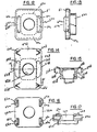
- the slider is depicted herein in various embodiments. Common or similar elements in the various embodiments will be identified by like reference numerals distinguished by differing alphabetic suffixes.
- the slider comprises a body member 42 having length L extending in the direction of the guide channel 22 into which the slider is received, a width W extending transversely between the side walls 24 and 26 and slidingly bearing thereagainst, and a thickness T extending between the base walls 28 and 30 and also slidingly bearing thereagainst.
- the means 34 for mounting the window to the slider is supported on the body member 42 medially of its length and width.
- Such means may comprise a ball stud having a threaded shank 44 terminating in a ball shaped head 46, rockably disposed in a complementary ball socket 48 formed in the body member. The fit of the ball head within the socket is sufficiently tight that no free play is allowed. Suitable washers and a nut 50 embrace the window 36 to mount the latter to the slider.
- the body member 42 has integral stiffly resilient projections arranged in opposed pairs 52 and 54, and 56 and 58 disposed longitudinally on opposite sides of the ball socket 48 and extending laterally in one direction, i.e., in the direction of the width W of the body members. These projections are formed of the same material as the body member and are simply extensions of it. These projections extend in the direction of and are intended to bear against the side walls 24 and 26. These projections are generally bow shaped having a laterally extending arcuate portion which is integrally attached at opposite ends to the body member. An opening 60 in the body member provides a space into which the bow shaped projections may be elastically deflected or squeezed as the slider is introduced into the guide channel.
- the lateral extent of the projections 52-58 should be such in relation to the maximum tolerance spacing between the side walls 24 and 26 that upon introducing the slider into the channel the projections will be squeezed slightly inwardly into the openings 60 to thereby bias the slider in one lateral direction in the channel against rattling.
- the design of the slider body is such as to prevent rattling in the guide channel 22 in the other lateral direction, i.e. in the direction of thickness T.
- the body is provided with integral stiffly resilient wing-like projections 62, 64, 66 and 68, extending laterally toward the base wall 28 of the guide channel.
- the lateral extent of these projections should be such in relation to the maximum tolerance spacing between the base walls 28 and 30 that upon introducing the slider into the guide channel the projections 62-68 will be deflected or squeezed slightly in a flattening direction to thereby bias the slider in the channel in the lateral direction against rattling.
- the projections 62-68 are generally triangularly shaped and extend laterally angularly toward the base wall 28 as best shown in Figs. 4 and 5 to bear thereagainst.
- the slider body with its projections is a one-piece molded part greatly simplifying the slider as compared particularly to the design in prior U.S. Patent 3,466,802.
- the other embodiments of the invention are modifications of the basic concept shown in Figs. 2-5 of a one-piece molded plastic body having integral stiffly resilient projections extending laterally from the body in two lateral directions T and W.
- the slider body 20a provided with a ball socket 48a, having a lateral flange portion 49 having projections 52a, 54a, 56a and 58a.
- These projections are arranged as were similar projections in the embodiment of Figs. 2-5, in opposed pairs disposed longitudinally on opposite sides of the ball socket 48a.
- the projections 62a and 64a which extend in the other lateral direction, i.e., toward base wall 28 when the slider is introduced into the guide channel, are arranged as a pair on opposite sides of the ball socket 48a and in alignment therewith.
- the projections are as before wing-like but in the form of regular trapezoids to provide a longer channel bearing edge 70a than the more pointed tip 70 of the Figs. 2-5 embodiment.
- the projections 52-58a while bow shaped, are connected at only one end to the body member, the other end 72 being free.
- projections extend just beyond the body portions 74 and 76 which are intended to ride the side walls 24 and 26 of the guide channel should lateral forces be applied to the slider overcoming the resilience of the projections 52a-58a and displacing the slider laterally in the channel.
- the slider body 20b has a lateral flange portion 49b from which projections 52b-58b extend as in the embodiment of Figs. 6-8.
- Projections in the form of a pair of bow shaped spring fingers 62b and 66b on one side of the socket 48b and 64b and 68b on the opposite side of the socket extend in the lateral direction T to bear against the base wall 28 of the guide channel.
- the projections 62b-68b are integral with the body flange 49b at one end but are free at the opposite end.
- Body portions 74b and 76b will as in the case of portions 74 and 76 in Fig. 6, limit the lateral displacement in one direction of the slider.
- the body member 42c has a lateral flange portion 49c with a depending marginal edge 51 rendering the slider somewhat hat-shaped in appearance.
- the flange portion 49c is longitudinally shorter than the preceding embodiments.
- the projections 52c and 54c are outwardly bowed portions of the marginal edge 51 and are stiffly resilient.
- the lateral flange portion 49 is provided with openings 60c opposite the bowed projections.
- Stiffly resilient wing-like projections 62c and 64c are disposed in the openings 60c and extend angularly toward and resiliently bear against the base wall 28 when the slider is introduced into the guide channel.
- the slider body 42d again has a lateral flange portion 49d with a pair of oppositely arranged integral, stiffly resilient lateral projections 52d and 54d aligned with ball socket 48d. Openings 60d in the flange portion 49d provide spaces into which the bows may flex upon squeezing during introduction of the slider into the channel guideway.
- Wing-like projections 62d, 64d, 66d and 68d arranged in pairs on opposite longitudinal sides of socket 48d are provided in complementary openings in the body and extend laterally to resiliently bear against the base wall 28 when the slider body is introduced in the guideway channel.
- a slider body 42e has a lateral flange portion 49e with bow shaped finger like projections 52e, 54e, 56e and 58e at its four corners.
- the slider is similar to that of Figs. 6-8 except the projections 62e, 64e, 66e and 68e are bowed fingers integral at one end with a slider body and free at the opposite ends as shown in Fig. 17.
Landscapes
- Engineering & Computer Science (AREA)
- Mechanical Engineering (AREA)
- Window Of Vehicle (AREA)
Applications Claiming Priority (2)
| Application Number | Priority Date | Filing Date | Title |
|---|---|---|---|
| US104765 | 1987-10-02 | ||
| US07/104,765 US4829630A (en) | 1987-10-02 | 1987-10-02 | Window slider |
Publications (2)
| Publication Number | Publication Date |
|---|---|
| EP0310451A2 true EP0310451A2 (de) | 1989-04-05 |
| EP0310451A3 EP0310451A3 (de) | 1989-08-16 |
Family
ID=22302253
Family Applications (1)
| Application Number | Title | Priority Date | Filing Date |
|---|---|---|---|
| EP88309176A Withdrawn EP0310451A3 (de) | 1987-10-02 | 1988-10-03 | Fenstergleitschuh |
Country Status (3)
| Country | Link |
|---|---|
| US (1) | US4829630A (de) |
| EP (1) | EP0310451A3 (de) |
| JP (1) | JPH01160724A (de) |
Cited By (2)
| Publication number | Priority date | Publication date | Assignee | Title |
|---|---|---|---|---|
| US5771534A (en) * | 1995-08-11 | 1998-06-30 | Consolidated Industrial Corporation | Slider block assembly for a vehicle window |
| ES2151806A1 (es) * | 1998-04-01 | 2001-01-01 | Daumal Castellon Melchor | Arrastrador con su carril perfeccionados para sistemas elevacristales. |
Families Citing this family (19)
| Publication number | Priority date | Publication date | Assignee | Title |
|---|---|---|---|---|
| JPH0645031Y2 (ja) * | 1989-03-29 | 1994-11-16 | アイシン精機株式会社 | ウインドレギユレータ装置 |
| JPH0725420Y2 (ja) * | 1989-07-17 | 1995-06-07 | 日本ケーブル・システム株式会社 | ウインドレギュレータ用摺動部材 |
| US5201144A (en) * | 1992-09-14 | 1993-04-13 | General Motors Corporation | Eccentrically located aperture in a cam slider for window regulator |
| US5469663A (en) * | 1994-11-04 | 1995-11-28 | Chrysler Corporation | Snap-in attachment of window pane lift plate to window regulator |
| US5647094A (en) * | 1995-08-30 | 1997-07-15 | Excel Industries | Sliding member for regulator assembly |
| JP4005737B2 (ja) * | 1999-03-01 | 2007-11-14 | 株式会社ニフコ | ウインドガラスの昇降用スライダー |
| KR100348051B1 (ko) * | 1999-12-30 | 2002-08-09 | 현대자동차주식회사 | 자동차용 도어 레귤레이터 |
| CN1229242C (zh) * | 2000-09-27 | 2005-11-30 | 因蒂尔汽车封闭装置公司 | 窗调节器槽的滑块装置 |
| KR20030008974A (ko) * | 2001-07-21 | 2003-01-29 | 현대자동차주식회사 | 차량용 파워 윈도우 레귤레이터 |
| US6550185B2 (en) * | 2001-08-02 | 2003-04-22 | Meritor Light Vehicle Technology, Llc | Vehicle door and window regulator assembly for driving a window in a helical path |
| US6855063B2 (en) * | 2001-11-28 | 2005-02-15 | J. R. Clancy, Inc. | Arbor guide shoe assembly for counterweight system |
| KR100463152B1 (ko) | 2002-04-19 | 2004-12-23 | 현대자동차주식회사 | 자동차의 도어 글래스 승강장치 |
| JP3912744B2 (ja) * | 2002-07-03 | 2007-05-09 | 株式会社大井製作所 | ウィンドウレギュレータ装置 |
| JP3953410B2 (ja) * | 2002-11-01 | 2007-08-08 | 富士重工業株式会社 | 車両用ウインドガラスの昇降用ガイド具 |
| EP1637376A1 (de) * | 2004-09-20 | 2006-03-22 | Grupo Antolin-Ingenieria, S.A. | Gleitschuh Anordnung |
| US9593271B2 (en) | 2011-09-22 | 2017-03-14 | Kaneka Corporation | Curable composition and cured product thereof |
| US20150256048A1 (en) * | 2012-09-26 | 2015-09-10 | Hi-Lex Corporation | Opening/closing body operation device |
| KR102035573B1 (ko) * | 2018-08-08 | 2019-10-23 | 대동하이렉스 주식회사 | 자동차 도어 윈도우 레귤레이터의 풀리 장착구조 |
| US20240300303A1 (en) * | 2023-03-09 | 2024-09-12 | One Piece Products | Automotive door window conversion kit and method |
Family Cites Families (11)
| Publication number | Priority date | Publication date | Assignee | Title |
|---|---|---|---|---|
| US1502644A (en) * | 1921-11-30 | 1924-07-22 | Campbell Metal Window Corp | Slidable window sash |
| US1621508A (en) * | 1925-05-25 | 1927-03-22 | Curtain Supply Co | Sash guide |
| DE1979494U (de) * | 1967-11-14 | 1968-02-22 | Porsche Kg | Kraftfahrzeug-tuer. |
| US3466803A (en) * | 1968-05-28 | 1969-09-16 | Gen Motors Corp | Guide arrangement |
| US3466802A (en) * | 1968-06-17 | 1969-09-16 | Gen Motors Corp | Slidable guide assembly |
| JPS51141123A (en) * | 1975-05-29 | 1976-12-04 | Nissan Motor Co Ltd | Guide device for raising and lowering window glass |
| DE2553549C3 (de) * | 1975-11-28 | 1983-11-03 | Webasto-Werk W. Baier GmbH & Co, 8035 Gauting | Gleitschuh für ein Fahrzeug- Schiebedach |
| US4633613A (en) * | 1983-12-09 | 1987-01-06 | Ohi Seisakusho Co., Ltd. | Window regulator for door |
| DE8413286U1 (de) * | 1984-04-30 | 1987-06-04 | Brose Fahrzeugteile GmbH & Co KG, 8630 Coburg | Gleitbacken aus Kunststoff, insbesondere für Fensterheber |
| DE3503547C1 (de) * | 1985-02-02 | 1986-05-22 | Adam Opel AG, 6090 Rüsselsheim | Gleitstück zur Führung von Fensterscheiben, insbesondere von Kraftfahrzeugen |
| DE3545224A1 (de) * | 1985-12-20 | 1987-07-02 | Bayerische Motoren Werke Ag | Gleitstueck an einer verschiebbaren fensterscheibe eines kraftfahrzeugs |
-
1987
- 1987-10-02 US US07/104,765 patent/US4829630A/en not_active Expired - Lifetime
-
1988
- 1988-10-03 EP EP88309176A patent/EP0310451A3/de not_active Withdrawn
- 1988-10-03 JP JP63247541A patent/JPH01160724A/ja active Pending
Cited By (2)
| Publication number | Priority date | Publication date | Assignee | Title |
|---|---|---|---|---|
| US5771534A (en) * | 1995-08-11 | 1998-06-30 | Consolidated Industrial Corporation | Slider block assembly for a vehicle window |
| ES2151806A1 (es) * | 1998-04-01 | 2001-01-01 | Daumal Castellon Melchor | Arrastrador con su carril perfeccionados para sistemas elevacristales. |
Also Published As
| Publication number | Publication date |
|---|---|
| EP0310451A3 (de) | 1989-08-16 |
| US4829630A (en) | 1989-05-16 |
| JPH01160724A (ja) | 1989-06-23 |
Similar Documents
| Publication | Publication Date | Title |
|---|---|---|
| US4829630A (en) | Window slider | |
| US4935986A (en) | Window slider | |
| CN1229242C (zh) | 窗调节器槽的滑块装置 | |
| EP0115826A2 (de) | Federscharnier für Brillenbügel | |
| CA1078634A (en) | Knob spring | |
| US4583805A (en) | Locking arrangement for electrical contact element insertable into housing chamber | |
| WO2002102259A3 (en) | An assembly for the stabilisation of vertebral bodies of the spine | |
| US4677714A (en) | Quick-release fastener | |
| US5847801A (en) | Hinge structure and bearing member for hinge in frame of spectacles | |
| DE10051693A1 (de) | Smartcard-Connector sowie Schaltkontaktelement, insbesondere für einen Smartcard-Connector | |
| DE102005059779B4 (de) | Flüssigkristallmodul | |
| JPH10227176A (ja) | ウインド昇降機構用ガイドスライダ | |
| JP2501496B2 (ja) | レ―ルへの取付装置 | |
| US6167781B1 (en) | System and apparatus for retaining position of cam follower | |
| US20050008270A1 (en) | Slider for a holding track of a window lifter | |
| DE3332371A1 (de) | Druckknopfschalter mit einem raststift im gehaeuse und einer herzfoermigen rastnut im schieber | |
| EP0412349B1 (de) | Schnappverschluss | |
| DE202018106094U1 (de) | Gehäuseanordnung für wenigstens einen Sensor | |
| JPH09158597A (ja) | 開口枠へのピボット扉の固定構造 | |
| JPH0222463Y2 (de) | ||
| JPH10153054A (ja) | コーナー継ぎ手 | |
| JPH0811547A (ja) | 摺動案内具 | |
| DE2458400A1 (de) | Schiebeschalter | |
| DE10154905C2 (de) | Rundsteckdoseneinsatz | |
| DE102022202185A1 (de) | Wischervorrichtung mit zumindest einer Endkappeneinheit und Verfahren zur Montage einer Wischervorrichtung |
Legal Events
| Date | Code | Title | Description |
|---|---|---|---|
| PUAI | Public reference made under article 153(3) epc to a published international application that has entered the european phase |
Free format text: ORIGINAL CODE: 0009012 |
|
| AK | Designated contracting states |
Kind code of ref document: A2 Designated state(s): DE FR GB IT SE |
|
| PUAL | Search report despatched |
Free format text: ORIGINAL CODE: 0009013 |
|
| AK | Designated contracting states |
Kind code of ref document: A3 Designated state(s): DE FR GB IT SE |
|
| STAA | Information on the status of an ep patent application or granted ep patent |
Free format text: STATUS: THE APPLICATION IS DEEMED TO BE WITHDRAWN |
|
| 18D | Application deemed to be withdrawn |
Effective date: 19900219 |