EP0310493A1 - Dispositif optoélectrique de détection et de localisation d'une source rayonnante - Google Patents
Dispositif optoélectrique de détection et de localisation d'une source rayonnante Download PDFInfo
- Publication number
- EP0310493A1 EP0310493A1 EP88402433A EP88402433A EP0310493A1 EP 0310493 A1 EP0310493 A1 EP 0310493A1 EP 88402433 A EP88402433 A EP 88402433A EP 88402433 A EP88402433 A EP 88402433A EP 0310493 A1 EP0310493 A1 EP 0310493A1
- Authority
- EP
- European Patent Office
- Prior art keywords
- diaphragm
- detector
- detection
- source
- optical
- Prior art date
- Legal status (The legal status is an assumption and is not a legal conclusion. Google has not performed a legal analysis and makes no representation as to the accuracy of the status listed.)
- Granted
Links
Images
Classifications
-
- G—PHYSICS
- G01—MEASURING; TESTING
- G01S—RADIO DIRECTION-FINDING; RADIO NAVIGATION; DETERMINING DISTANCE OR VELOCITY BY USE OF RADIO WAVES; LOCATING OR PRESENCE-DETECTING BY USE OF THE REFLECTION OR RERADIATION OF RADIO WAVES; ANALOGOUS ARRANGEMENTS USING OTHER WAVES
- G01S3/00—Direction-finders for determining the direction from which infrasonic, sonic, ultrasonic or electromagnetic waves, or particle emission, not having a directional significance, are being received
- G01S3/78—Direction-finders for determining the direction from which infrasonic, sonic, ultrasonic or electromagnetic waves, or particle emission, not having a directional significance, are being received using electromagnetic waves other than radio waves
- G01S3/782—Systems for determining direction or deviation from predetermined direction
- G01S3/783—Systems for determining direction or deviation from predetermined direction using amplitude comparison of signals derived from static detectors or detector systems
Definitions
- the present invention relates to an optoelectric device for detecting and locating a radiating source.
- the location is obtained in relation to two reference axes, such as the site and deposit axes, which gives the direction of the source relative to the device; with two devices we can produce two intersecting directional locations and therefore measure the spatial location of the source.
- radiating source is meant either a distant source or a closer but small source so as to assimilate it to a point source or to infinity.
- laser alert detectors is not intended than detecting the presence of a threat, this in a large field around the carrier, for example 360 ° in deposit and 90 ° in site.
- the aforementioned location devices are generally not intended to operate in such large fields. Their adaptation to these fields leads to a decrease in sensitivity incompatible with the detection of the useful signal.
- An object of the invention is to remedy the aforementioned drawbacks by combining the four quadrant detector with a simple circular opening upstream forming a diaphragm.
- the absence of focusing optics allows such a device to simultaneously have a large field which can be greater than ⁇ 45 ° and a large pupil related only to the size of the detector.
- the device can also be used in any spectral band and as well for the reception of continuous or impulse emissions.
- the resolution is a few degrees and the sensitivity, linked to the detection surface, is important.
- an optoelectric device for detecting and locating a radiating source comprising a plane detector with four quadrants preceded by a receiving optical element, and circuits for processing and deviating from the four signals detected to measure the depointing angular of the source with respect to a reference optical direction, the device being characterized in that the optical element is a plane diaphragm parallel to the detector, forming an opaque cover with the exception of a transparent circular area.
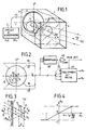
- the device comprises a housing 1 for isolating the four-quadrant detector device 2 from ambient radiation.
- This flat detector is mounted on a flat face 5 at the bottom of the housing.
- a diaphragm 3 is contained in a plane parallel to the detector device.
- the diaphragm has been partially cut to clarify the representation. It has a transparent part or an opening, for example circular with a diameter ⁇ d (FIG. 3), through which the light rays pass.
- the remaining part of the diaphragm 3 is of zero transparency and forms an opaque cover.
- the diaphragm is preceded by a transparent window 4 which constitutes the front face of the housing 1 so as to isolate the device from the environment and, in particular, avoid the entry of dust.
- the window 4 may be provided with a deposit 7 (FIG. 3) forming an optical filter and located on the internal side of the housing 1, or be made of an absorbent glass limiting the spectral band.
- the transparent part 4 forming a window can be transferred to the level of the opening of the diaphragm 3 which simplifies the equipment but which imposes a fixed value of the diameter ⁇ d of the diaphragm.
- the device is completed by electronic processing and deviation circuits 6 which calculate the deviations EX and EY from point C corresponding to the center of the circle of the light spot T formed by the incident rays passing through the circular aperture of the diaphragm.
- the radiation comes from the source S and can be considered received in the form of a beam of parallel rays.
- the axis Z passing through the center O of the detector and the center O ′ of the opening is the optical axis Z of the device.
- the direction ZS is that presented by the source S and the angle ⁇ the angular depointing of this source relative to the device.
- the coordinates of deviations XC and YC correspond to the deviations in elevation and in bearing of the source detected along the two Cartesian axes X and Y.
- Figure 2 shows the electronic circuits.
- the four detection outputs V1 to V4 are applied to the deviation circuits 61.
- a second channel can be provided, having an adder 62 at the input followed by a threshold comparator circuit 63 to validate the detection of a radiant source of determined intensity.
- the validation signal is transmitted in particular to the deviation circuits 61.
- the shape of the hole can be different from the circular one shown.
- a square hole gives a deviation proportional to tg ⁇ , ⁇ being the depointing angle, and therefore non-linear with this parameter.
- a round hole makes it possible to linearize the response curve as a function of the depointing.
- FIG. 4 represents this response curve for the depointing along the Y axis in relation to FIG. 3 which corresponds to a section along the Y and Z axes.
- the distance D can be chosen to be reduced, which considerably increases the detection field without changing the sensitivity of the device.
- the electronic processing and calculation circuits 6 can be produced in a small dimension as a solid circuit and incorporated in the housing at the rear of the face 5. It is also possible, for the calculation, to use an available auxiliary computer.
- the selection of the useful radiation that is to say that from the source S to be located, is obtained in a known manner with a sensitive detector in the radiation spectra corresponding to the sources to be detected.
- the operating spectral range may, in the case of detection of laser illuminators, be located in the near or far infrared. It is not excluded to use in addition the optical filtering advantageously carried out by deposition on the internal wall of the window 4.
Landscapes
- Physics & Mathematics (AREA)
- Electromagnetism (AREA)
- Engineering & Computer Science (AREA)
- General Physics & Mathematics (AREA)
- Radar, Positioning & Navigation (AREA)
- Remote Sensing (AREA)
- Length Measuring Devices By Optical Means (AREA)
- Photometry And Measurement Of Optical Pulse Characteristics (AREA)
Abstract
Description
- La présente invention concerne un dispositif optoélectrique de détection et de localisation de source rayonnante.
- La localisation est obtenue par rapport à deux axes de référence, tels les axes site et gisement, ce qui donne la direction de la source par rapport au dispositif ; avec deux dispositifs on peut produire deux localisations directionnelles sécantes et donc mesurer la localisation spatiale de la source.
- Par source rayonnante on entend, soit une source éloignée, soit une source plus proche mais de faible dimension de manière à l'assimiler à une source ponctuelle ou à l'infini.
- Il est connu d'effectuer une écartométrie dite deux axes, d'une source lumineuse ponctuelle ou assimilable à une source à l'infini, en utilisant un détecteur à quatre quadrants. Le détecteur est situé en aval d'un objectif optique qui concentre le rayonnement incident reçu de la source sous forme d'un faisceau parallèle pour en former une tache lumineuse de dimension moyenne déterminée dans le plan de photodétection. Les quatre signaux respectifs détectés sont traités par sommation et pondération pour mesurer le dépointage angulaire en site et en gisement de la source par rapport à l'axe optique du dispositif. Le brevet français 2.420.144 (ou US 4.286.760) décrit un dispositif de détection et de localisation de source rayonnante de ce genre.
- Face à l'utilisation de plus en plus fréquente des lasers dans les système d'armes (télémètres, illuminateurs, ...) il devient nécessaire de prévenir l'équipage d'un véhicule ou d'un aéronef en cas d'illumination de celui-ci. Des équipements correspondants appelés détecteurs d'alerte laser, n'ont pour but que de détecter la présence d'une menace, ceci dans un champ important autour du porteur, par exemple de 360° en gisement et 90° en site.
- Les dispositifs de localisation précités ne sont généralement pas prévus pour fonctionner dans des champs aussi importants. Leur adaptation à ces champs entraîne une baisse de sensibilité incompatible avec la détection du signal utile.
- Un objet de l'invention est de remédier aux inconvénients précités en combinant le détecteur quatre quadrants avec une simple ouverture circulaire en amont formant diaphragme.
- L'absence d'optique de focalisation permet à un tel dispositif d'avoir simultanément un grand champ qui peut être supérieur à ± 45° et une grande pupille liée seulement à la dimension du détecteur. Le dispositif peut en outre être utilisé dans n'importe quelle bande spectrale et aussi bien pour la réception d'émissions continues ou impulsionnelles. La résolution est de quelques degrés et la sensibilité, liée à la surface de détection, est importante.
- Selon l'invention il est réalisé un dispositif optoélectrique de détection et de localisation de source rayonnante comportant un détecteur plan à quatre quadrants précédé d'un élément optique récepteur, et des circuits de traitement et d'écartométrie des quatre signaux détectés pour mesurer le dépointage angulaire de la source par rapport à une direction optique de référence, le dispositif étant caractérisé en ce que l'élément optique est un diaphragme plan parallèle au détecteur, formant un cache opaque à l'exception d'une zone circulaire transparente.
- Les caractéristiques et avantages de l'invention apparaîtront dans la description qui suit donnée à titre d'exemple, à l'aide des figures annexées qui représentent :
- - Fig.1, un schéma d'un dispositif de détection et de localisation conforme à l'invention ;
- - Fig.2, un bloc-diagramme relatif au détecteur et au circuit électronique ;
- - Fig.3,un schéma en coupe transversale du dispositif ;
- - Fig.4, la courbe de réponse du dispositif.
- En se reportant à la figure 1, le dispositif comporte un boîtier 1 pour isoler le dispositif détecteur à quatre quadrants 2 du rayonnement ambiant. Ce détecteur plan est monté sur une face plane 5 au fond du boîtier. Parallèlement au détecteur 2, un diaphragme 3 est contenu dans un plan parallèle au dispositif détecteur. Le diaphragme a été partiellement découpé pour clarifier la représentation. Il comporte une partie transparente ou une ouverture, par exemple circulaire de diamètre ⌀d (figure 3), par laquelle passent les rayons lumineux. La partie restante du diaphragme 3 est de transparence nulle et forme un cache opaque.
- De manière préférentielle, le diaphragme est précédé d'un hublot transparent 4 qui constitue la face avant du boîtier 1 de manière à isoler le dispositif de l'environnement et, en particulier, éviter l'entrée de poussières.
- Le hublot 4 peut être pourvu d'un dépôt 7 (figure 3) formant un filtre optique et situé côté interne au boîtier 1, ou être constitué d'un verre absorbant limitant la bande spectrale.
- Selon une variante de réalisation, la partie transparente 4 formant hublot peut être reportée au niveau de l'ouverture du diaphragme 3 ce qui simplifie l'équipement mais qui impose une valeur fixe du diamètre ⌀d du diaphragme.
- Le dispositif est complété par les circuits électroniques de traitement et d'écartométrie 6 qui calculent les écarts EX et EY du point C correspondant au centre du cercle de la tache lumineuse T formée par les rayons incidents passant par l'ouverture circulaire du diaphragme. Le rayonnement provient de la source S et peut être considéré reçu sous forme d'un faisceau de rayons parallèles. L'axe Z passant par le centre O du détecteur et le centre O′ de l'ouverture est l'axe optique Z du dispositif. La direction ZS est celle présentée par la source S et l'angle ϑ le dépointage angulaire de cette source par rapport au dispositif. Les coordonnées d'écarts XC et YC correspondent aux écarts en site et en gisement de la source détectée selon les deux axes cartésiens X et Y .
- La figure 2 représente les circuits électroniques. Les quatre sorties de détection V1 à V4 sont appliquées aux circuits d'écartométrie 61. Par ailleurs, une deuxième voie peut être prévue ayant à l'entrée un sommateur 62 suivi d'un circuit comparateur à seuil 63 pour valider la détection d'une source rayonnante d'intensité déterminée. Le signal de validation est transmis notamment aux circuits d'écartométrie 61.
- Les écarts EX et EY sont déduits par le calcul à partir des formules classiques :

- Il est possible d'adapter la forme de la courbe d'écartométrie (figure 4) en jouant sur la distance D présentée entre le diaphragme 3 et le détecteur 2 (figure 3), ainsi que sur la forme et la dimension du trou du diaphragme.
- La forme du trou peut être différente de celle circulaire représentée. Par exemple un trou carré donne une écartométrie proportionnelle à tgϑ,ϑ étant l'angle de dépointage, et donc non linéaire avec ce paramètre. Un trou rond par contre permet de linéariser la courbe de réponse en fonction du dépointage.
- La figure 4 représente cette courbe de réponse pour le dépointage selon l'axe Y en relation avec la figure 3 qui correspond à une coupe selon les axes Y et Z.
- La distance D peut être choisie réduite ce qui accroît considérablement le champ de détection sans changer la sensibilité du dispositif.
- Le système est optimisé dans le cas de l'ouverture circulaire envisagée; le diamètre ⌀d est choisi égal au rayon R du détecteur 2. Dans ce cas, l'écartomètre sature lorsque XC=⌀d/2 soit tg ϑX=⌀d/2D. Il en est de même pour EX et ϑY (figure 4).
- Dans une réalisation plus complexe on peut considérer les paramètres D et ⌀d réglables en utilisant un diaphragme variable et déplaçable selon des techniques connues.
- Les circuits électroniques de traitement et de calcul 6 peuvent être réalisés sous faible dimension en circuit solide et incorporés dans le boîtier à l'arrière de la face 5. On peut également, pour le calcul, utiliser un calculateur annexe disponible. La sélection du rayonnement utile, c'est-à-dire celui provenant de la source S à localiser, est obtenue de manière connue avec un détecteur sensible dans les spectres de radiation correspondant aux sources à détecter. Le domaine spectral d'exploitation peut, dans le cas de détection d'illuminateurs laser se situer dans l'infrarouge proche ou lointain. Il n'est pas exclu d'utiliser en complément le filtrage optique réalisé avantageusement par dépôt sur la paroi interne du hublot 4.
- Dans le cas d'utilisation pour la détection d'alerte laser émettant à 1,06µm on trouve des détecteurs standards de diamètre 16mm. En plaçant un diaphragme 3 circulaire d'ouverture 8mm à une distance de 4mm devant le détecteur on obtient un signal d'écartométrie linéaire en fonction du dépointage dans un champ de ± 45°. La surface des pupilles est dans cet exemple de 0,5cm².
Claims (10)
Applications Claiming Priority (2)
| Application Number | Priority Date | Filing Date | Title |
|---|---|---|---|
| FR8713666 | 1987-10-02 | ||
| FR8713666A FR2621398B1 (fr) | 1987-10-02 | 1987-10-02 | Dispositif optoelectrique de detection et de localisation d'une source rayonnante |
Publications (2)
| Publication Number | Publication Date |
|---|---|
| EP0310493A1 true EP0310493A1 (fr) | 1989-04-05 |
| EP0310493B1 EP0310493B1 (fr) | 1993-12-08 |
Family
ID=9355481
Family Applications (1)
| Application Number | Title | Priority Date | Filing Date |
|---|---|---|---|
| EP88402433A Expired - Lifetime EP0310493B1 (fr) | 1987-10-02 | 1988-09-27 | Dispositif optoélectrique de détection et de localisation d'une source rayonnante |
Country Status (5)
| Country | Link |
|---|---|
| US (1) | US4946277A (fr) |
| EP (1) | EP0310493B1 (fr) |
| CA (1) | CA1321632C (fr) |
| DE (1) | DE3886159T2 (fr) |
| FR (1) | FR2621398B1 (fr) |
Cited By (8)
| Publication number | Priority date | Publication date | Assignee | Title |
|---|---|---|---|---|
| US4946277A (en) * | 1987-10-02 | 1990-08-07 | Thomson-Csf | Opto-electronic device for detecting and locating a radiant source |
| FR2675593A1 (fr) * | 1991-04-18 | 1992-10-23 | Elgelec | Tete optoelectronique a balayage permettant sa localisation par rapport a une source lumineuse emettrice. |
| FR2726903A1 (fr) * | 1994-11-10 | 1996-05-15 | Thomson Csf | Ecartometre integre |
| EP0770884A1 (fr) | 1995-10-27 | 1997-05-02 | Thomson-Csf | Procédé de détection par désignation laser et dispositif d'écartométrie à détecteur matriciel correspondant |
| DE4125714C2 (de) * | 1990-08-03 | 2001-03-08 | Thomson Csf | Verfahren zum Schutz eines passiven optoelektronischen Überwachungs- oder Verfolgungsgerätes gegenüber einer Laseranstrahlung |
| WO2008089007A1 (fr) | 2007-01-12 | 2008-07-24 | Sunsight Holdings, Llc | Dispositifs de surveillance d'alignement d'antenne avec capteur solaire à déflecteur |
| WO2011058190A1 (fr) | 2009-11-16 | 2011-05-19 | Opto-Mst Sensoren Und Systeme Gmbh | Dispositif et procédé de localisation de sources de rayonnement optique modulées |
| WO2012152654A1 (fr) * | 2011-05-09 | 2012-11-15 | Ophthalmosystem Gmbh | Procédé et détecteur de position pour la détermination de la position relative d'une source de rayonnement |
Families Citing this family (17)
| Publication number | Priority date | Publication date | Assignee | Title |
|---|---|---|---|---|
| FR2653562B1 (fr) * | 1989-10-23 | 1992-02-28 | Aerospatiale | Systeme pour la localisation d'un mobile. |
| IL99346A (en) * | 1991-08-30 | 1996-05-14 | Israel Aircraft Ind Ltd | Boresight system and calibration method |
| US5502568A (en) * | 1993-03-23 | 1996-03-26 | Wacom Co., Ltd. | Optical position detecting unit, optical coordinate input unit and optical position detecting method employing a pattern having a sequence of 1's and 0's |
| JP3400485B2 (ja) * | 1993-03-23 | 2003-04-28 | 株式会社ワコム | 光学式位置検出装置および光学式座標入力装置 |
| FR2709840B1 (fr) * | 1993-09-10 | 1995-10-20 | Thomson Csf | Dispositif optique de type fish-eye pour la détection et la localisation d'une source rayonnante. |
| JPH07261920A (ja) * | 1994-03-17 | 1995-10-13 | Wacom Co Ltd | 光学式位置検出装置および光学式座標入力装置 |
| US5604695A (en) * | 1995-06-05 | 1997-02-18 | Her Majesty The Queen, As Represented By The Minister Of National Defence Of Her Majesty's Canadian Government | Analog high resolution laser irradiation detector (HARLID) |
| US5771092A (en) * | 1997-05-08 | 1998-06-23 | Her Majesty The Queen In Right Of Canada, As Represented By The Minister Of National Defence | Wavelength agile receiver with noise neutralization and angular localization capabilities (WARNALOC) |
| WO1999010136A1 (fr) * | 1997-08-28 | 1999-03-04 | Proteus Corporation | Etalonnage laser de systemes robotiques |
| US8878114B2 (en) | 2012-08-16 | 2014-11-04 | Nanohmics, Inc. | Apparatus and methods for locating source of and analyzing electromagnetic radiation |
| EP2722650A1 (fr) | 2012-10-18 | 2014-04-23 | Lambda-X | Détection de position angulaire |
| CN104280011B (zh) * | 2014-09-04 | 2017-01-25 | 兰州空间技术物理研究所 | 一种基于光栅衍射型探测器的激光告警装置 |
| US10267675B2 (en) * | 2014-12-05 | 2019-04-23 | Monash University | Multi-directional optical receiver |
| CN107561495A (zh) * | 2017-08-28 | 2018-01-09 | 成都航天通信设备有限责任公司 | 一种基于激光跟踪的室内三维定位方法 |
| US10267889B1 (en) | 2017-11-15 | 2019-04-23 | Avalex Technologies Corporation | Laser source location system |
| CN113514152A (zh) * | 2021-06-18 | 2021-10-19 | 中国人民解放军国防科技大学 | 一种可鉴别信号来向的微弱光信号检测系统 |
| LT7041B (lt) | 2022-05-20 | 2024-01-10 | Valstybinis mokslinių tyrimų institutas Fizinių ir technologijos mokslų centras | Detektavimo įrenginys, sistema ir būdas, skirti optinio pluošto kritimo kampui nustatyti |
Citations (7)
| Publication number | Priority date | Publication date | Assignee | Title |
|---|---|---|---|---|
| GB1027457A (en) * | 1962-01-30 | 1966-04-27 | British Aircraft Corp A T Ltd | Improvements relating to two-dimensional photoelectric indicating means |
| US3486030A (en) * | 1966-08-16 | 1969-12-23 | Bendix Corp | Earth albedo sensor and sun sensor |
| US3764198A (en) * | 1971-06-07 | 1973-10-09 | Philips Corp | Objective system consisting of a diaphragm and a single lens |
| US3954340A (en) * | 1973-03-13 | 1976-05-04 | Ab Bofors | Method of and apparatus for target tracking |
| GB1459386A (en) * | 1965-04-13 | 1976-12-22 | Philco Ford Corp | Radiant energy tracking systems |
| EP0004227A1 (fr) * | 1978-03-14 | 1979-09-19 | Thomson-Csf | Appareil de détection optoélectrique et de localisation angulaire d'un objet lumineux et son utilisation |
| FR2583197A1 (fr) * | 1985-06-07 | 1986-12-12 | Thomson Csf | Systeme de commande de positionnement d'une marque sur un ecran et application a la commande d'ordres a distance |
Family Cites Families (7)
| Publication number | Priority date | Publication date | Assignee | Title |
|---|---|---|---|---|
| US4006356A (en) * | 1961-10-27 | 1977-02-01 | Aeronutronic Ford Corporation | Radiant energy tracking device |
| US3287562A (en) * | 1964-02-28 | 1966-11-22 | Kollsman Instr Corp | Photosensitive scanning means for rotating an image with respect to a light modulator |
| US3496367A (en) * | 1965-04-12 | 1970-02-17 | Bendix Corp | Light sensing device including means for sensing wide angle and fine angle light |
| US3723013A (en) * | 1970-10-23 | 1973-03-27 | Atomic Energy Commission | Alignment system |
| US4081669A (en) * | 1973-10-26 | 1978-03-28 | Klingman Iii Edwin E | Recognition system for class II robots |
| US4843227A (en) * | 1986-09-11 | 1989-06-27 | Minolta Camera Kabushiki Kaisha | Focus detecting apparatus with both passive and active focus capability |
| FR2621398B1 (fr) * | 1987-10-02 | 1989-07-28 | Thomson Csf | Dispositif optoelectrique de detection et de localisation d'une source rayonnante |
-
1987
- 1987-10-02 FR FR8713666A patent/FR2621398B1/fr not_active Expired
-
1988
- 1988-09-27 US US07/249,894 patent/US4946277A/en not_active Expired - Fee Related
- 1988-09-27 DE DE88402433T patent/DE3886159T2/de not_active Expired - Fee Related
- 1988-09-27 EP EP88402433A patent/EP0310493B1/fr not_active Expired - Lifetime
- 1988-09-29 CA CA000578797A patent/CA1321632C/fr not_active Expired - Fee Related
Patent Citations (7)
| Publication number | Priority date | Publication date | Assignee | Title |
|---|---|---|---|---|
| GB1027457A (en) * | 1962-01-30 | 1966-04-27 | British Aircraft Corp A T Ltd | Improvements relating to two-dimensional photoelectric indicating means |
| GB1459386A (en) * | 1965-04-13 | 1976-12-22 | Philco Ford Corp | Radiant energy tracking systems |
| US3486030A (en) * | 1966-08-16 | 1969-12-23 | Bendix Corp | Earth albedo sensor and sun sensor |
| US3764198A (en) * | 1971-06-07 | 1973-10-09 | Philips Corp | Objective system consisting of a diaphragm and a single lens |
| US3954340A (en) * | 1973-03-13 | 1976-05-04 | Ab Bofors | Method of and apparatus for target tracking |
| EP0004227A1 (fr) * | 1978-03-14 | 1979-09-19 | Thomson-Csf | Appareil de détection optoélectrique et de localisation angulaire d'un objet lumineux et son utilisation |
| FR2583197A1 (fr) * | 1985-06-07 | 1986-12-12 | Thomson Csf | Systeme de commande de positionnement d'une marque sur un ecran et application a la commande d'ordres a distance |
Non-Patent Citations (2)
| Title |
|---|
| LASER FOCUS, vol. 17, no. 4, avril 1981, pages 72-80, Newton, Mass., US; P.T. BALLARD: "Detecting laser illumination for military countermeasures" * |
| MECHANICAL ENGINEERING, vol. 96, no. 11, novembre 1974, page 43, New York, US; "sun gate sensor System" * |
Cited By (12)
| Publication number | Priority date | Publication date | Assignee | Title |
|---|---|---|---|---|
| US4946277A (en) * | 1987-10-02 | 1990-08-07 | Thomson-Csf | Opto-electronic device for detecting and locating a radiant source |
| DE4125714C2 (de) * | 1990-08-03 | 2001-03-08 | Thomson Csf | Verfahren zum Schutz eines passiven optoelektronischen Überwachungs- oder Verfolgungsgerätes gegenüber einer Laseranstrahlung |
| FR2675593A1 (fr) * | 1991-04-18 | 1992-10-23 | Elgelec | Tete optoelectronique a balayage permettant sa localisation par rapport a une source lumineuse emettrice. |
| WO1992018875A1 (fr) * | 1991-04-18 | 1992-10-29 | Elgelec | Tete optoelectronique a balayage permettant sa localisation par rapport a une source lumineuse emettrice |
| FR2726903A1 (fr) * | 1994-11-10 | 1996-05-15 | Thomson Csf | Ecartometre integre |
| EP0712009A1 (fr) * | 1994-11-10 | 1996-05-15 | Thomson-Csf | Ecartomètre intégré |
| US5719670A (en) * | 1994-11-10 | 1998-02-17 | Thomson-Csf | Integrated direction finder |
| EP0770884A1 (fr) | 1995-10-27 | 1997-05-02 | Thomson-Csf | Procédé de détection par désignation laser et dispositif d'écartométrie à détecteur matriciel correspondant |
| WO2008089007A1 (fr) | 2007-01-12 | 2008-07-24 | Sunsight Holdings, Llc | Dispositifs de surveillance d'alignement d'antenne avec capteur solaire à déflecteur |
| EP2127020A4 (fr) * | 2007-01-12 | 2014-05-28 | Sunsight Holding Llc | Dispositifs de surveillance d'alignement d'antenne avec capteur solaire à déflecteur |
| WO2011058190A1 (fr) | 2009-11-16 | 2011-05-19 | Opto-Mst Sensoren Und Systeme Gmbh | Dispositif et procédé de localisation de sources de rayonnement optique modulées |
| WO2012152654A1 (fr) * | 2011-05-09 | 2012-11-15 | Ophthalmosystem Gmbh | Procédé et détecteur de position pour la détermination de la position relative d'une source de rayonnement |
Also Published As
| Publication number | Publication date |
|---|---|
| DE3886159D1 (de) | 1994-01-20 |
| DE3886159T2 (de) | 1994-04-07 |
| US4946277A (en) | 1990-08-07 |
| FR2621398A1 (fr) | 1989-04-07 |
| CA1321632C (fr) | 1993-08-24 |
| FR2621398B1 (fr) | 1989-07-28 |
| EP0310493B1 (fr) | 1993-12-08 |
Similar Documents
| Publication | Publication Date | Title |
|---|---|---|
| EP0310493B1 (fr) | Dispositif optoélectrique de détection et de localisation d'une source rayonnante | |
| EP0419320B1 (fr) | Dispositif d'harmonisation automatique pour un système optronique | |
| EP0004227A1 (fr) | Appareil de détection optoélectrique et de localisation angulaire d'un objet lumineux et son utilisation | |
| EP0015199A1 (fr) | Dispositif optoélectrique de localisation de source rayonnante et système de repérage de direction comportant de tels dispositifs | |
| RU2223515C1 (ru) | Устройство обнаружения оптических и оптико-электронных объектов | |
| US20230047931A1 (en) | Coaxial lidar system using a diffractive waveguide | |
| CN114144698A (zh) | 用于激光雷达窗口的抗反射标贴 | |
| US12235438B2 (en) | MEMS wavelength selectable switch for adaptive wavelength filtering | |
| WO2012089957A1 (fr) | Dispositif de detection d'une direction angulaire dans laquelle se trouve un objet | |
| WO2015033036A1 (fr) | Equipements de véhicule automobile intégrant un dispositif de mesure de distance d'objets | |
| FR2476326A1 (fr) | Dispositif pour determiner la position angulaire d'une cible eclairee par des impulsions lumineuses | |
| US6433330B1 (en) | Sun optical limitation illumination detector (SOLID) | |
| EP0556042B1 (fr) | Elément optique avec champ optique à grand angle | |
| EP0301947B1 (fr) | Dispositif optoélectrique de détection et de localisation d'une source rayonnante | |
| FR2690584A1 (fr) | Dispositif d'acquisition de données et système de communication comportant un tel dispositif. | |
| EP0138646B1 (fr) | Dispositif d'analyse de champ spatial pour la localisation angulaire d'objects rayonnants | |
| US8124925B2 (en) | Simulation detector having multiple sensor surfaces for detecting incident radiation | |
| FR2606522A1 (fr) | Dispositif et procede optique de mise au point photoelectrique, notamment pour microscopes d'operations chirurgicales | |
| EP1380811B1 (fr) | Dispositif optique de mesure de distances | |
| RU2191417C1 (ru) | Оптико-электронный прибор для дистанционного обнаружения систем скрытого видеонаблюдения | |
| EP0071492A1 (fr) | Dispositif de surveillance panoramique optique | |
| US4742222A (en) | Selective optical detector apparatus utilizing longitudinal chromatic aberration | |
| FR2709840A1 (fr) | Dispositif optique de type fish-eye pour la détection et la localisation d'une source rayonnante. | |
| EP3591428B1 (fr) | Système et procédé de suivi d'une cible et de compensation de turbulences atmosphériques | |
| EP3797510B1 (fr) | Systeme d'observation panoramique pour plate-forme |
Legal Events
| Date | Code | Title | Description |
|---|---|---|---|
| PUAI | Public reference made under article 153(3) epc to a published international application that has entered the european phase |
Free format text: ORIGINAL CODE: 0009012 |
|
| AK | Designated contracting states |
Kind code of ref document: A1 Designated state(s): DE GB IT |
|
| RAP3 | Party data changed (applicant data changed or rights of an application transferred) |
Owner name: THOMSON-CSF |
|
| 17P | Request for examination filed |
Effective date: 19890527 |
|
| 17Q | First examination report despatched |
Effective date: 19910715 |
|
| GRAA | (expected) grant |
Free format text: ORIGINAL CODE: 0009210 |
|
| AK | Designated contracting states |
Kind code of ref document: B1 Designated state(s): DE GB IT |
|
| ITF | It: translation for a ep patent filed | ||
| REF | Corresponds to: |
Ref document number: 3886159 Country of ref document: DE Date of ref document: 19940120 |
|
| RAP2 | Party data changed (patent owner data changed or rights of a patent transferred) |
Owner name: THOMSON-CSF |
|
| GBT | Gb: translation of ep patent filed (gb section 77(6)(a)/1977) |
Effective date: 19940211 |
|
| PLBE | No opposition filed within time limit |
Free format text: ORIGINAL CODE: 0009261 |
|
| STAA | Information on the status of an ep patent application or granted ep patent |
Free format text: STATUS: NO OPPOSITION FILED WITHIN TIME LIMIT |
|
| 26N | No opposition filed | ||
| PGFP | Annual fee paid to national office [announced via postgrant information from national office to epo] |
Ref country code: DE Payment date: 20000814 Year of fee payment: 13 |
|
| PGFP | Annual fee paid to national office [announced via postgrant information from national office to epo] |
Ref country code: GB Payment date: 20000818 Year of fee payment: 13 |
|
| PG25 | Lapsed in a contracting state [announced via postgrant information from national office to epo] |
Ref country code: GB Free format text: LAPSE BECAUSE OF NON-PAYMENT OF DUE FEES Effective date: 20010927 |
|
| REG | Reference to a national code |
Ref country code: GB Ref legal event code: IF02 |
|
| PG25 | Lapsed in a contracting state [announced via postgrant information from national office to epo] |
Ref country code: DE Free format text: LAPSE BECAUSE OF NON-PAYMENT OF DUE FEES Effective date: 20020501 |
|
| GBPC | Gb: european patent ceased through non-payment of renewal fee |
Effective date: 20010927 |
|
| PG25 | Lapsed in a contracting state [announced via postgrant information from national office to epo] |
Ref country code: IT Free format text: LAPSE BECAUSE OF NON-PAYMENT OF DUE FEES;WARNING: LAPSES OF ITALIAN PATENTS WITH EFFECTIVE DATE BEFORE 2007 MAY HAVE OCCURRED AT ANY TIME BEFORE 2007. THE CORRECT EFFECTIVE DATE MAY BE DIFFERENT FROM THE ONE RECORDED. Effective date: 20050927 |